
Komatsu WD600-3 Wheel Dozer Shop Manual (SEBM022902) – Complete Service, Repair & Maintenance PDF
Original price was: $89.95.$59.95Current price is: $59.95.
The complete Komatsu WD600-3 shop manual, document SEBM022902, covering serial numbers 50001 and up. Full structure and function, testing and adjusting, disassembly and assembly, maintenance standards, hydraulic and electrical diagrams for the WD600-3 wheel dozer with SAA6D170E-3 engine.
Description
Komatsu WD600-3 Shop Manual — Complete Workshop Reference
This is the complete Komatsu WD600-3 shop manual, document number SEBM022902, covering wheel dozer models from serial number 50001 and up. It is the comprehensive workshop reference for this machine, spanning mechanical, hydraulic, electrical and powertrain systems. Every procedure, specification and tolerance in this PDF was written for the technician working on the WD600-3 in a service environment, not for the operator’s daily checks.
The manual is organised into six major sections: General, Structure and Function, Testing and Adjusting, Disassembly and Assembly, Maintenance Standard, and Others. Together they form a complete repair and diagnostic resource for the WD600-3 wheel dozer.
File Details
- Manual Type: Shop Manual
- Brand: Komatsu
- Model: WD600-3
- Serial Number: 50001 and up
- Engine: SAA6D170E-3
- Document Number: SEBM022902
- Language: English
- Pages: Approximately 1,450
- File Format: PDF
Note: The WD600-3 mounts the SAA6D170E-3 engine. For detailed engine overhaul procedures, the manual refers to the separate 6D170-3 Series Engine Shop Manual. Engine-related testing and adjusting values are included in this manual’s standard value tables.
Chapters Covered
- 01 General
- 10 Structure and Function
- 20 Testing and Adjusting
- 30 Disassembly and Assembly
- 40 Maintenance Standard
- 90 Others
01 — General
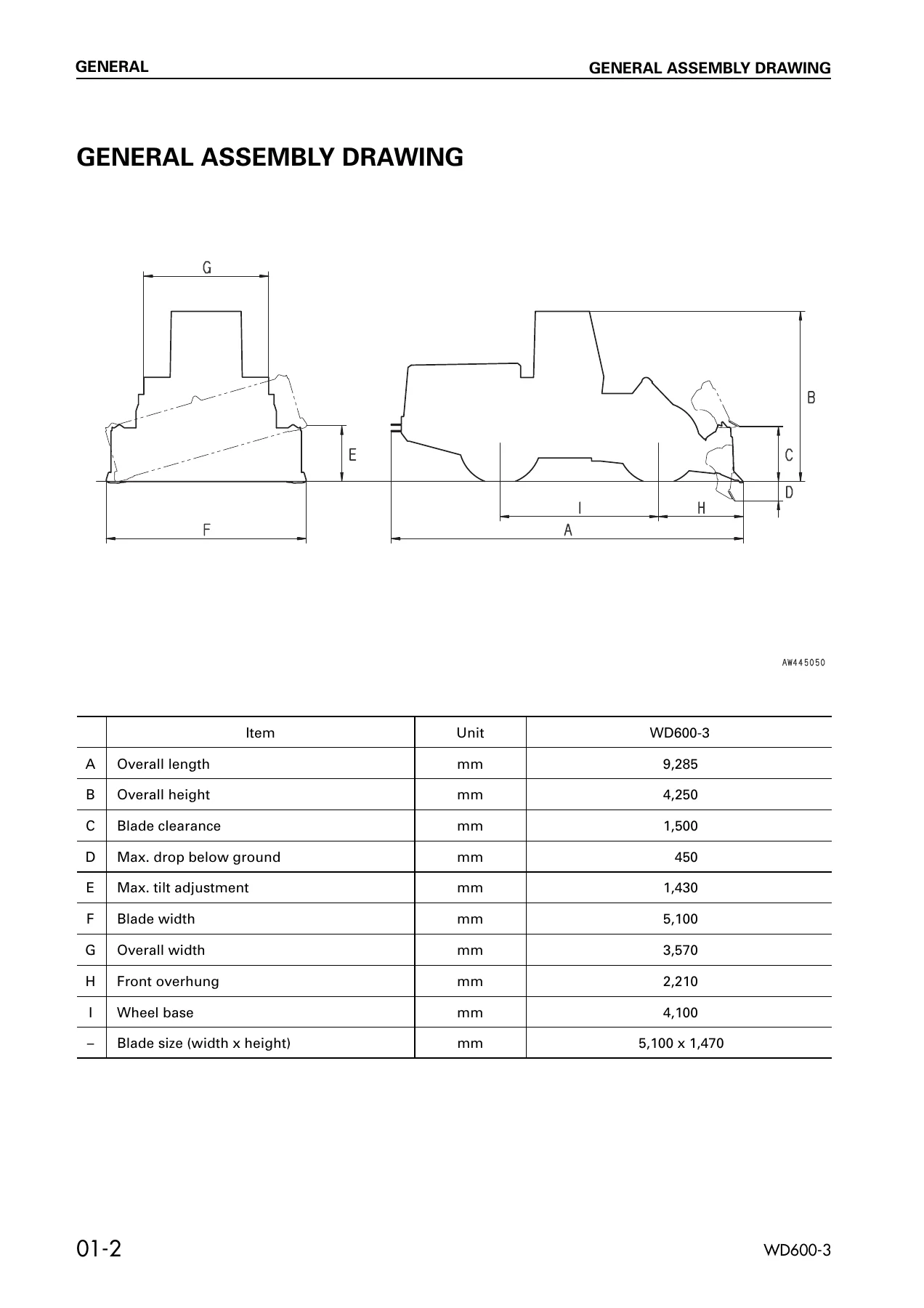
The opening section provides the general assembly drawing with overall machine dimensions, a specifications table, a weight table for major components and assemblies, and a list of lubricants and water with ambient temperature ranges. This gives you the baseline reference data for the WD600-3 before any work begins.
10 — Structure and Function
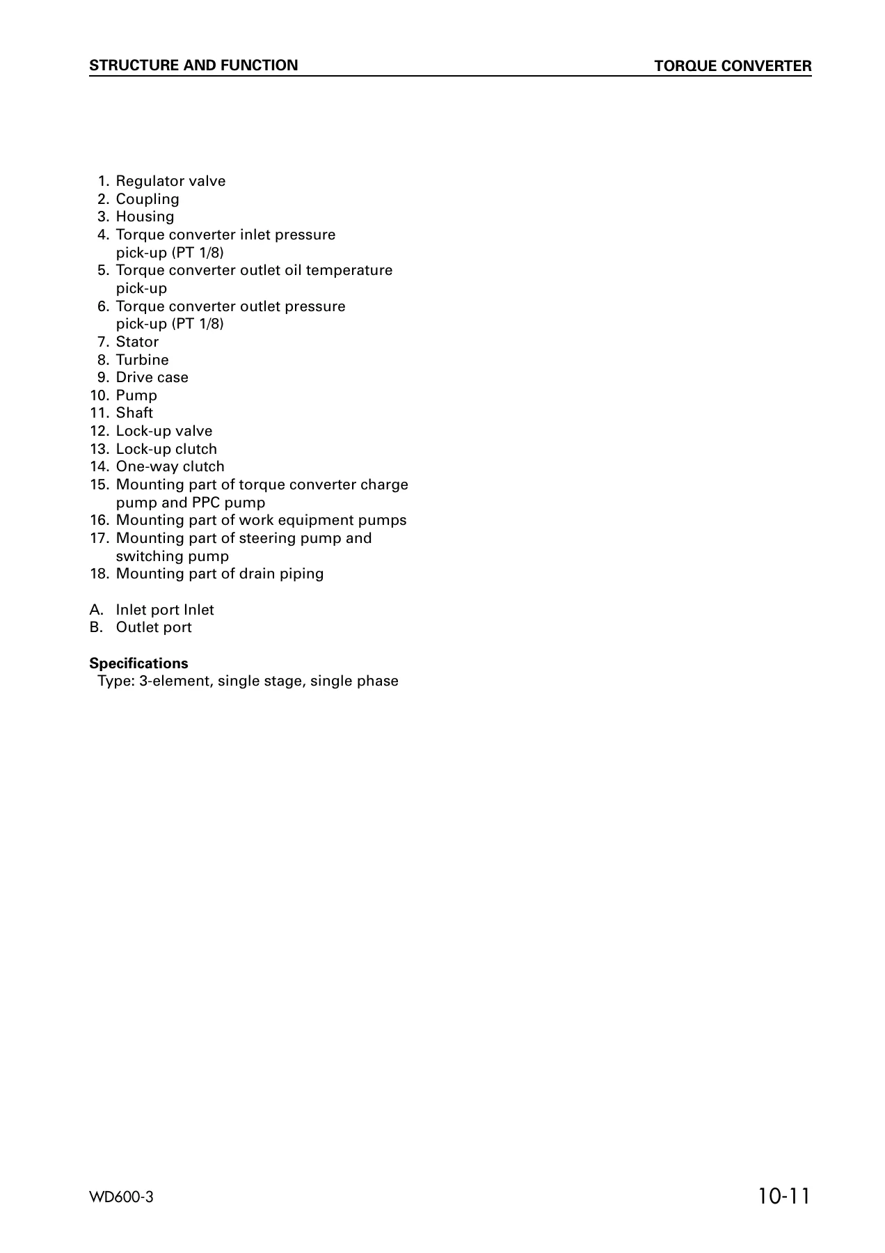
This is the theory-of-operation section. It walks through the cooling system, the complete power train path from engine flywheel through torque converter, transmission, transfer, drive shafts, axles, differentials and final drives. It also covers the steering system including the Orbit-roll valve, steering valve, stop valve and emergency steering piping; the brake system including brake valve, charge valve, accumulator, slack adjuster and parking brake; hydraulic piping, PPC valve, work equipment valve, air conditioner, machine monitor system, engine starting and stop circuits, pre-heating circuit, transmission and joystick steering system, and throttle control system. Every major assembly is described with cutaway illustrations and function explanations, making this section the reference for understanding how the WD600-3 systems interact.
20 — Testing and Adjusting
This section contains the standard value tables for engine, chassis and electrical parts, followed by detailed testing and adjusting procedures. Covered procedures include measuring engine speed, exhaust gas colour, adjusting valve clearance, testing and adjusting injector lift, measuring compression pressure and blow-by pressure, measuring engine oil pressure, replacing fan belt auto-tensioner, testing alternator belt tension, handling the fuel circuit, measuring fuel pump outlet pressure, bleeding air from the fuel circuit, measuring exhaust temperature, adjusting speed sensors, measuring torque converter and transmission oil pressures, emergency manual spool operation, steering oil pressure testing, steering stop valve adjustment, brake oil pressure testing, brake disc wear measurement, brake performance measurement, parking brake testing and adjustment, accumulator charge cut-in and cut-out pressure, PPC oil pressure, work equipment hydraulic pressure, work equipment lever linkage adjustment, main monitor speedometer calibration, bleeding air, and releasing remaining pressure in hydraulic circuits.
The troubleshooting portion of this section is extensive, with dedicated modes for engine system (S mode), engine controller system (EA mode), main monitor system (M mode), maintenance monitor system (K mode), electrical system (E mode), hydraulic and mechanical system (H mode), transmission control system (T mode), joystick steering system (J mode), and throttle control system (TH mode). Each mode provides fault codes, symptom-based diagnostics, and step-by-step testing procedures.
30 — Disassembly and Assembly
This section provides removal, installation, disassembly and assembly procedures for the major components of the WD600-3. Covered components include starting motor, alternator, radiator, engine and torque converter assembly, torque converter, transmission, transmission valve, transfer, center support, drive shaft, front axle, rear axle, front and rear differential, differential gear, final drive, Orbit-roll, steering cylinder, steering valve, brake valve, slack adjuster, brake, hydraulic pump, hydraulic tank, hydraulic filter, PPC valve, DECO valve, work equipment valve, pitch and tilt cylinder, lift cylinder, center hinge pin, work equipment, bulkhead, floor frame, counterweight, fuel tank, cab, stop valve, accumulator, accumulator charge valve, parking brake solenoid valve, diverter valve, emergency steering pump, parking brake, parking brake calipers, parking brake pad, rear tires, air conditioner compressor, air conditioner condenser, receiver tank, air conditioner unit, and monitor. Each procedure includes special tools, tightening torques, and precautions for safe work.
40 — Maintenance Standard
This section gives the judgement standards for inspection of disassembled parts. It covers engine mount, transmission mount, torque converter, lock-up valve, torque converter regulator valve, transmission, transmission solenoid valve, transmission control valve, transfer, drive shaft, center support, differential, non-spin differential, final drive, axle mount, center hinge pin, steering column, steering valve, emergency steering pump, diverter valve, steering cylinder mount, brake valve, slack adjuster, brake, parking brake, hydraulic pump, PPC valve, work equipment valve, hydraulic cylinder, work equipment linkage, and ROPS canopy. Each entry provides the standard size, tolerance, repair limit, and the remedy — whether to replace, repair, adjust or retighten.
90 — Others
The final section contains the brake circuit diagram, the hydraulic circuit diagram for the power train, the full hydraulic circuit diagram, and the complete electric circuit diagram for machines equipped with joystick steering and automatic shift control. These diagrams are essential for tracing faults through the WD600-3‘s systems.
What This Manual Enables You to Do
With this Komatsu WD600-3 shop manual on hand, you can perform the full range of service and repair tasks on the wheel dozer. The testing and adjusting section lets you diagnose hydraulic, electrical and powertrain faults using the manufacturer’s own pressure values, flow rates and electrical measurements. The disassembly and assembly procedures guide you through component removal and rebuild with the correct torque values and special tool references. The maintenance standard section gives you the wear limits and clearances to judge whether a part can be reused, repaired or must be replaced.
This is not a generic repair guide. It is the SEBM022902 document written specifically for the WD600-3 serial number range 50001 and up, with the SAA6D170E-3 engine. The hydraulic circuit diagrams, the electric circuit diagrams, and the troubleshooting flowcharts are all specific to this machine. If you are maintaining, repairing or rebuilding a WD600-3, this manual gives you the same reference information the workshop uses.
IMAGES PREVIEW
Instant PDF Delivery — No Shipping, No Waiting
The manual is delivered as a PDF download immediately after purchase. There is no physical book to ship, no waiting for delivery, and no risk of a damaged or lost parcel. You can open the file on any device — desktop, laptop, tablet or smartphone — and print only the pages you need for the job at hand. Whether you are working in the workshop or in the field, the complete Komatsu WD600-3 shop manual is available the moment you need it.
Reviews
There are no reviews yet.