Description
This is the complete KTM 250 SX repair manual for the 2020 model year, published under article number 3206383en by KTM Sportmotorcycle GmbH in April 2019. It covers both the European and US variants of the 250 SX — identified by the factory model codes F6301TO (EU) and F6375TO (US) — and is written for the fully trained mechanic working with the correct KTM special tools and workshop equipment. Every system on the motorcycle is addressed: from the WP XACT 5548 air fork and the WP XACT 5750 shock absorber through the MIKUNI TMX 38 carburetor, the hydraulically operated multidisc clutch, the transmission internals, the exhaust control system, the ignition and charging circuits, and the complete engine teardown and reassembly sequence.
File Details
- Manual type: Repair manual (workshop/service)
- Brand: KTM
- Model: 250 SX (2020)
- Covered models: 250 SX EU (F6301TO), 250 SX US (F6375TO)
- Article number: 3206383en
- Publication date: 04/2019
- Language: English
- Page count: 312 pages
- File format: PDF
Chapters Covered
- Means of representation — symbols and typographical formats
- Safety advice — degrees of risk and work rules
- Important notes — warranty, fuel and auxiliary substances, spare parts, figures
- Serial numbers — vehicle identification number, type label, engine number, fork part number, shock absorber article number
- Motorcycle — lifting, parking, starting
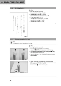
- Fork, triple clamp — XACT 5548 air suspension, air pressure setting, compression and rebound damping, bleeding, dust boot cleaning, fork leg removal and installation, fork servicing, air cartridge and shock absorber cartridge disassembly and assembly, steering head bearing
- Handlebar, controls — handlebar position, clutch lever, throttle cable routing and play, rubber grip
- Frame — footrests, frame inspection
- Shock absorber, link fork — high- and low-speed compression damping, rebound damping, spring preload, riding sag, shock absorber removal and installation, heim joint, damper disassembly and assembly, link fork and fork bearing
- Exhaust system — main silencer, glass fiber yarn filling
- Air filter — box cover, filter removal and installation, cleaning, box sealing
- Fuel tank, seat, trim — filler cap, seat, fuel tank, fuel tap
- Mask, fender — front fender, start number plate
- Wheels — tire pressure and condition, wheel bearings, brake discs, spoke tension, rim run-out, front and rear wheel removal and installation, drivetrain kit
- Wiring harness — ignition timing map adjustment connector
- Brake system — front and rear brake linings, brake fluid levels, brake fluid changing, hand and foot brake lever adjustment
- Engine — removal, installation, complete disassembly and assembly, individual component work
- Carburetor — choke, idle speed, float chamber, removal and installation, jet needle, throttle slide, float needle valve, float level
- Clutch — hydraulic fluid level and change, clutch inspection
- Water pump, cooling system — coolant level and antifreeze, draining and refilling, coolant pipe
- Exhaust control — auxiliary spring adjustment
- Lubrication system — gear oil change and level
- Ignition system — ignition system check, ignition coil primary and secondary windings, spark plug, spark plug connector, alternator charging coil, crankshaft speed sensor
- Technical data — engine, wear limits, tightening torques, capacities, chassis, electrical system, tires, fork, shock absorber, carburetor
- Cleaning and care
- Storage
- Service schedule — required and recommended work
- Wiring diagram
- Substances, auxiliary substances, special tools, standards, abbreviations
Altogether the manual walks a technician through the complete 250 SX — from routine maintenance such as air filter cleaning and chain tension right down to splitting the engine cases, pressing crank webs, measuring piston-to-cylinder clearance, setting the Z-distance on the exhaust control flap, and bleeding the WP XACT damper on the vacuum pump. Each procedure is written with the prerequisite steps listed first, the torque values called out inline and the special KTM tool numbers named, so nothing has to be guessed.
Engine, Transmission and Exhaust Control
The engine section is the heart of the KTM 250 SX repair manual. It documents the full teardown sequence for the 249 cm³ single-cylinder two-stroke: shift lever, clutch push rod, alternator cover, kick starter lever, cylinder head, cylinder, piston, water pump cover, clutch cover, clutch discs, clutch basket, balancer shaft, kick starter shaft and intermediate gear, shift shaft, shift drum locating unit, rotor, reed valve housing, left engine case, shift rails, shift drum, shift forks, transmission shafts and crankshaft. Then it reverses the process for assembly, with the X-distance and Z-distance checks placed exactly where they belong in the sequence so the engine goes back together without a knock or a compression loss. Alongside this, the manual covers individual-part work: crankshaft bearing inner race removal and installation, connecting rod replacement on the press, crankshaft run-out at the bearing pin, cylinder bore measurement on both axes, piston ring end gap, piston-to-cylinder mounting clearance, and the exhaust control flap adjustment that shapes the engine’s power delivery.
Complete PDF Bookmark Tree
Complete Bookmarks
The complete bookmarks in the “KTM 250 SX 2020 Repair Manual PDF – Complete Workshop Guide 3206383en” are as follows:
+1 MEANS OF REPRESENTATIONp. 9
1.1 Symbols usedp. 9
1.2 Formats usedp. 9
+2 SAFETY ADVICEp. 10
2.1 Repair Manualp. 10
2.2 Safety advicep. 10
2.3 Degrees of risk and symbolsp. 10
2.4 Work rulesp. 10
+3 IMPORTANT NOTESp. 11
3.1 Manufacturer and implied warrantyp. 11
3.2 Fuel, auxiliary substancesp. 11
3.3 Spare parts, accessoriesp. 11
3.4 Figuresp. 11
+4 SERIAL NUMBERSp. 12
4.1 Vehicle identification numberp. 12
4.2 Type labelp. 12
4.3 Engine numberp. 12
4.4 Fork part numberp. 12
4.5 Shock absorber article numberp. 13
+5 MOTORCYCLEp. 14
5.1 Raising the motorcycle with a lift standp. 14
5.2 Removing the motorcycle from the lift standp. 14
5.3 Startingp. 14
5.4 Starting the motorcycle to check the functionp. 15
+6 FORK, TRIPLE CLAMPp. 16
6.1 Air suspension XACT 5548p. 16
6.2 Checking the basic setting of the forkp. 16
6.3 Adjusting the fork air pressurep. 17
6.4 Adjusting the compression damping of the forkp. 18
6.5 Adjusting the rebound damping of the forkp. 18
6.6 Bleeding the fork legsp. 19
6.7 Cleaning the dust boots of the fork legsp. 20
6.8 Removing the fork legsp. 20
6.9 Installing the fork legsp. 21
6.10 Removing the fork protectorp. 22
6.11 Installing the fork protectorp. 22
6.12 Servicing the forkp. 22
6.13 Disassembling the fork legsp. 23
6.14 Disassembling the air cartridgep. 27
6.15 Disassembling the shock absorber cartridgep. 29
6.16 Checking the fork legsp. 30
6.17 Assembling the shock absorber cartridgep. 32
6.18 Assembling the air cartridge (250 SX EU)p. 34
6.19 Assembling the air cartridge (250 SX US)p. 36
6.20 Assembling the fork legs (250 SX EU)p. 38
6.21 Assembling the fork legs (250 SX US)p. 44
6.22 Lubricating the steering head bearingp. 50
6.23 Removing the lower triple clampp. 50
6.24 Installing the lower triple clampp. 51
6.25 Checking steering head bearing playp. 53
6.26 Adjusting steering head bearing playp. 54
6.27 Changing the steering head bearingp. 54
+7 HANDLEBAR, CONTROLSp. 57
7.1 Handlebar positionp. 57
7.2 Adjusting the handlebar positionp. 57
7.3 Adjusting the basic position of the clutch leverp. 58
7.4 Checking throttle cable routingp. 58
7.5 Checking throttle cable playp. 59
7.6 Adjusting throttle cable playp. 60
7.7 Checking the rubber gripp. 60
+8 FRAMEp. 62
8.1 Changing the footrestsp. 62
8.2 Checking the framep. 63
+9 SHOCK ABSORBER, LINK FORKp. 64
9.1 Adjusting the high-speed compression damping of the shock absorberp. 64
9.2 Adjusting the low-speed compression damping of the shock absorberp. 64
9.3 Adjusting the rebound damping of the shock absorberp. 65
9.4 Measuring the rear wheel dimension unloadedp. 66
9.5 Checking the static sag of the shock absorberp. 66
9.6 Checking the riding sag of the shock absorberp. 67
9.7 Adjusting the spring preload of the shock absorberp. 67
9.8 Adjusting the riding sagp. 68
9.9 Removing the shock absorberp. 69
9.10 Installing the shock absorberp. 71
9.11 Checking the shock absorber linkagep. 73
9.12 Checking the heim joint for playp. 75
9.13 Changing the heim jointp. 75
9.14 Servicing the shock absorberp. 77
9.15 Removing the springp. 77
9.16 Disassembling the damperp. 78
9.17 Disassembling the piston rodp. 80
9.18 Disassembling the seal ring retainerp. 81
9.19 Changing the pilot bushingp. 81
9.20 Checking the damperp. 82
9.21 Removing the heim jointp. 83
9.22 Installing the heim jointp. 84
9.23 Assembling seal ring retainerp. 84
9.24 Assembling the piston rodp. 85
9.25 Assembling the damper (250 SX EU)p. 87
9.26 Assembling the damper (250 SX US)p. 89
9.27 Bleeding and filling the damperp. 91
9.28 Filling damper with nitrogenp. 94
9.29 Installing the spring (250 SX EU)p. 95
9.30 Installing the spring (250 SX US)p. 96
9.31 Checking the fork bearing for playp. 97
9.32 Removing the link forkp. 98
9.33 Installing the link forkp. 100
9.34 Changing the fork bearingp. 102
9.35 Checking the link forkp. 104
+10 EXHAUST SYSTEMp. 105
10.1 Removing the main silencerp. 105
10.2 Installing the main silencerp. 105
10.3 Changing the glass fiber yarn filling in the main silencerp. 105
+11 AIR FILTERp. 107
11.1 Removing the air filter box coverp. 107
11.2 Installing the air filter box coverp. 107
11.3 Removing the air filterp. 108
11.4 Installing the air filterp. 109
11.5 Cleaning the air filter and air filter boxp. 109
11.6 Sealing the air filter boxp. 110
11.7 Preparing air filter box cover for securingp. 110
+12 FUEL TANK, SEAT, TRIMp. 111
12.1 Opening fuel tank filler capp. 111
12.2 Closing the fuel tank filler capp. 111
12.3 Removing the seatp. 112
12.4 Mounting the seatp. 112
12.5 Removing the fuel tankp. 113
12.6 Installing the fuel tankp. 114
12.7 Fuel tapp. 115
+13 MASK, FENDERp. 116
13.1 Removing front fenderp. 116
13.2 Installing front fenderp. 116
13.3 Removing the start number platep. 116
13.4 Installing the start number platep. 116
+14 WHEELSp. 117
14.1 Checking tire pressurep. 117
14.2 Checking the tire conditionp. 117
14.3 Checking the wheel bearing for playp. 118
14.4 Checking the brake discsp. 118
14.5 Checking spoke tensionp. 119
14.6 Checking the rim run-outp. 119
+14.7 Front wheelp. 120
14.7.1 Removing the front wheelp. 120
14.7.2 Installing the front wheelp. 121
14.7.3 Changing the front wheel bearingp. 122
14.7.4 Changing the front brake discp. 123
+14.8 Rear wheelp. 123
14.8.1 Removing the rear wheelp. 123
14.8.2 Installing the rear wheelp. 124
14.8.3 Changing the rear wheel bearingp. 125
14.8.4 Changing the rear brake discp. 127
14.8.5 Checking the chain for dirtp. 128
14.8.6 Cleaning the chainp. 128
14.8.7 Checking the chain tensionp. 129
14.8.8 Checking the chain, rear sprocket, engine sprocket, and chain guidep. 129
14.8.9 Adjusting the chain tensionp. 132
14.8.10 Changing the drivetrain kitp. 133
+15 WIRING HARNESSp. 137
15.1 Plug-in connector of ignition timing map adjustmentp. 137
+16 BRAKE SYSTEMp. 138
16.1 Checking the front brake liningsp. 138
16.2 Changing the front brake liningsp. 138
16.3 Checking the free travel of the hand brake leverp. 140
16.4 Adjusting the basic position of the hand brake leverp. 141
16.5 Checking the front brake fluid levelp. 141
16.6 Adding front brake fluidp. 142
16.7 Changing the front brake fluidp. 143
16.8 Checking the brake linings of the rear brakep. 145
16.9 Changing the rear brake liningsp. 145
16.10 Checking the free travel of foot brake leverp. 147
16.11 Adjusting the basic position of the foot brake leverp. 148
16.12 Checking the rear brake fluid levelp. 148
16.13 Adding rear brake fluidp. 149
16.14 Changing the rear brake fluidp. 150
+17 ENGINEp. 152
17.1 Removing the enginep. 152
17.2 Installing the enginep. 156
+17.3 Engine disassemblyp. 162
17.3.1 Clamping the engine into the engine assembly standp. 162
17.3.2 Removing the shift leverp. 162
17.3.3 Removing the clutch push rodp. 162
17.3.4 Draining the gear oilp. 163
17.3.5 Removing the spacerp. 163
17.3.6 Removing the alternator coverp. 163
17.3.7 Removing the kick starter leverp. 164
17.3.8 Removing the cylinder headp. 164
17.3.9 Removing the cylinderp. 165
17.3.10 Removing the pistonp. 166
17.3.11 Removing the water pump coverp. 166
17.3.12 Removing the clutch coverp. 167
17.3.13 Removing the clutch discsp. 168
17.3.14 Removing the clutch basketp. 169
17.3.15 Removing the balancer shaftp. 170
17.3.16 Removing the kick starter shaftp. 171
17.3.17 Removing the kick starter intermediate gearp. 171
17.3.18 Removing the shift shaftp. 171
17.3.19 Removing the shift drum locating unitp. 171
17.3.20 Removing the locking leverp. 172
17.3.21 Removing the rotorp. 172
17.3.22 Removing the reed valve housingp. 173
17.3.23 Removing the left engine case sectionp. 173
17.3.24 Removing the shift railsp. 174
17.3.25 Removing the shift drump. 174
17.3.26 Removing the shift forksp. 174
17.3.27 Removing the transmission shaftsp. 174
17.3.28 Removing the crankshaftp. 175
+17.4 Working on individual partsp. 176
17.4.1 Working on the right section of the engine casep. 176
17.4.2 Working on the left section of the engine casep. 177
17.4.3 Removing the crankshaft bearing inner racep. 178
17.4.4 Installing the crankshaft bearing inner racep. 179
17.4.5 Changing the connecting rod, conrod bearing, and crank pinp. 179
17.4.6 Checking the crankshaft run-out at the bearing pinp. 181
17.4.7 Checking/measuring the cylinderp. 181
17.4.8 Removing the exhaust controlp. 182
17.4.9 Checking the exhaust controlp. 184
17.4.10 Installing the exhaust controlp. 186
17.4.11 Cylinder – Nikasil® coatingp. 189
17.4.12 Checking/measuring the pistonp. 189
17.4.13 Checking the piston ringp. 190
17.4.14 Measuring the piston/cylinder mounting clearancep. 191
17.4.15 Disassemble the reed valve housingp. 191
17.4.16 Checking the reed valve housing, reed valve and intake flangep. 192
17.4.17 Assembling the reed valve housingp. 193
17.4.18 Working on the clutch coverp. 194
17.4.19 Checking the clutchp. 197
17.4.20 Preassembling shift shaftp. 198
17.4.21 Checking the shift mechanismp. 199
17.4.22 Disassembling the main shaftp. 200
17.4.23 Disassembling the countershaftp. 201
17.4.24 Checking the transmissionp. 201
17.4.25 Assembling the main shaftp. 203
17.4.26 Assembling the countershaftp. 203
17.4.27 Checking the kick starterp. 205
17.4.28 Preassembling the kick starter shaftp. 205
+17.5 Engine assemblyp. 207
17.5.1 Installing the crankshaftp. 207
17.5.2 Installing the transmission shaftsp. 207
17.5.3 Installing the shift forksp. 208
17.5.4 Installing the shift drump. 208
17.5.5 Installing the shift railsp. 208
17.5.6 Installing the left section of the engine casep. 209
17.5.7 Installing the reed valve housingp. 209
17.5.8 Installing the rotorp. 210
17.5.9 Installing the locking leverp. 211
17.5.10 Installing the shift drum locating unitp. 211
17.5.11 Installing the shift shaftp. 212
17.5.12 Installing the kick starter intermediate gearp. 212
17.5.13 Installing the kick starter shaftp. 212
17.5.14 Installing the balancer shaftp. 213
17.5.15 Installing the clutch basketp. 214
17.5.16 Installing the clutch discsp. 215
17.5.17 Installing the clutch coverp. 217
17.5.18 Installing the water pump coverp. 218
17.5.19 Installing the pistonp. 219
17.5.20 Installing the cylinderp. 219
17.5.21 Checking the X-distancep. 220
17.5.22 Adjusting the X-distancep. 221
17.5.23 Adjusting the Z-distancep. 221
17.5.24 Installing the cylinder headp. 224
17.5.25 Installing the kick starter leverp. 224
17.5.26 Installing the alternator coverp. 225
17.5.27 Installing the spacerp. 225
17.5.28 Gear oil drain plug, installingp. 225
17.5.29 Installing the clutch push rodp. 226
17.5.30 Installing the shift leverp. 226
17.5.31 Removing the engine from the engine assembly standp. 226
+18 CARBURETORp. 227
18.1 Chokep. 227
18.2 Carburetor – adjusting the idle speedp. 227
18.3 Emptying the carburetor float chamberp. 228
18.4 Removing the carburetorp. 229
18.5 Installing the carburetorp. 231
18.6 Checking/setting the carburetor componentsp. 233
18.7 Disassembling the carburetorp. 233
18.8 Checking the choke slidep. 236
18.9 Checking the jet needlep. 237
18.10 Checking the throttle slidep. 237
18.11 Checking the float needle valvep. 237
18.12 Assembling the carburetorp. 238
18.13 Checking/adjusting the float levelp. 240
+19 CLUTCHp. 242
19.1 Checking/correcting the fluid level of the hydraulic clutchp. 242
19.2 Changing the hydraulic clutch fluidp. 243
19.3 Checking the clutchp. 244
+20 WATER PUMP, COOLING SYSTEMp. 252
20.1 Cooling systemp. 252
20.2 Checking the antifreeze and coolant levelp. 252
20.3 Checking the coolant levelp. 253
20.4 Draining the coolantp. 253
20.5 Refilling with coolantp. 254
20.6 Changing the coolant pipep. 255
+21 EXHAUST CONTROLp. 260
21.1 Engine characteristic – adjusting the auxiliary springp. 260
+22 LUBRICATION SYSTEMp. 261
22.1 Changing the gear oilp. 261
22.2 Draining the gear oilp. 262
22.3 Filling in gear oilp. 262
22.4 Checking the gear oil levelp. 263
22.5 Adding the gear oilp. 263
+23 IGNITION SYSTEMp. 265
23.1 Checking the ignition systemp. 265
23.2 Ignition coil – checking the primary windingp. 266
23.3 Ignition coil – checking the secondary windingp. 267
23.4 Checking the spark plug connectorp. 267
23.5 Changing the spark plugp. 267
23.6 Changing the spark plug and spark plug connectorp. 268
23.7 Alternator – checking the charging coil of the ignitionp. 269
23.8 Checking the crankshaft speed sensorp. 269
+24 TECHNICAL DATAp. 271
24.1 Enginep. 271
24.2 Tolerance, engine wear limitsp. 271
24.3 Engine tightening torquesp. 272
+24.4 Capacitiesp. 273
24.4.1 Gear oilp. 273
24.4.2 Coolantp. 273
24.4.3 Fuelp. 273
24.5 Chassisp. 273
24.6 Electrical systemp. 274
24.7 Tiresp. 274
+24.8 Forkp. 274
24.8.1 250 SX EUp. 274
24.8.2 250 SX USp. 275
+24.9 Shock absorberp. 275
24.9.1 250 SX EUp. 275
24.9.2 250 SX USp. 276
24.10 Chassis tightening torquesp. 276
+24.11 Carburetorp. 278
24.11.1 Carburetor – basic setting for sandy surfacesp. 278
+24.12 Carburetor tuningp. 278
24.12.1 Carburetor tuningp. 278
24.12.2 General carburetor tuningp. 279
+25 CLEANING, CAREp. 280
25.1 Cleaning the motorcyclep. 280
+26 STORAGEp. 282
26.1 Storagep. 282
26.2 Preparing for use after storagep. 283
+27 SERVICE SCHEDULEp. 284
27.1 Additional informationp. 284
27.2 Required workp. 284
27.3 Recommended workp. 285
+28 WIRING DIAGRAMp. 286
29 SUBSTANCESp. 288
30 AUXILIARY SUBSTANCESp. 290
31 SPECIAL TOOLSp. 292
32 STANDARDSp. 305
33 LIST OF ABBREVIATIONSp. 306
+INDEXp. 307
Ap. 307
Bp. 307
Cp. 307
Dp. 307
Ep. 307
Fp. 308
Gp. 309
Hp. 309
Ip. 309
Jp. 309
Lp. 309
Mp. 309
Pp. 310
Rp. 310
Sp. 310
Tp. 310
Vp. 311
Wp. 311
Chassis, Suspension and Brakes
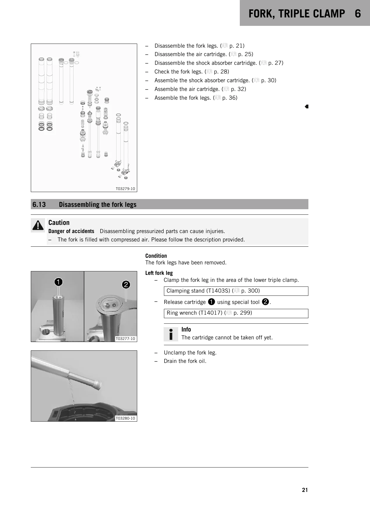
For the chassis side, the KTM 250 SX 2020 repair manual covers the WP XACT 5548 air fork in depth — including air pressure adjustment with the fork airpump, compression and rebound clicker settings, fork leg removal and installation, dust boot cleaning, and complete disassembly of the air cartridge on the left leg and the shock absorber cartridge on the right. The rear is handled with equal depth: WP XACT 5750 shock absorber, high- and low-speed compression damping, rebound damping, spring preload and riding sag, damper disassembly and reassembly on the vacuum pump, nitrogen filling, heim joint replacement, and the complete link fork and fork bearing service. Brake work — lining changes front and rear, brake fluid changing, and lever free travel — is covered with the same level of detail as the powertrain.
Electrical, Fuel and Cooling Systems
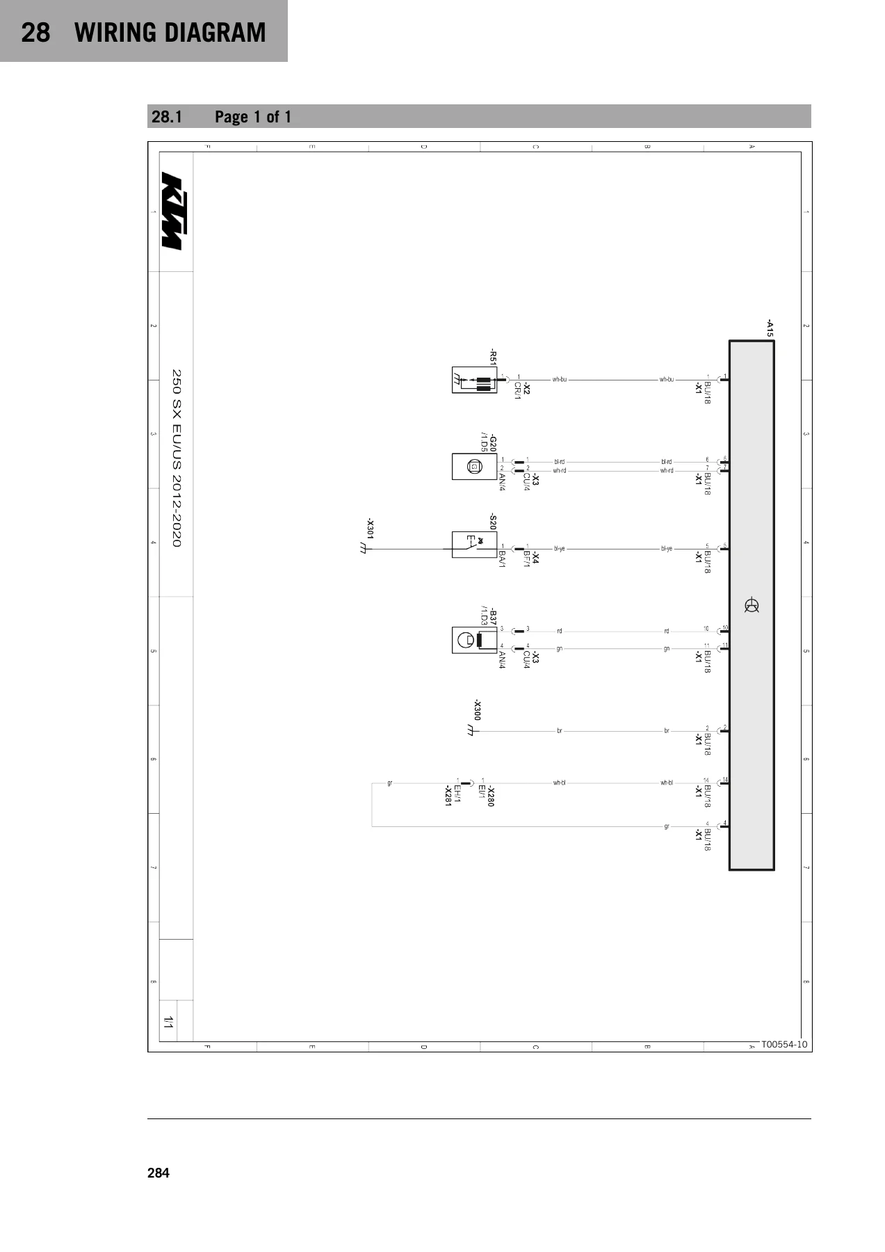
The carburetor chapter documents the MIKUNI TMX 38, including idle speed adjustment, choke slide, jet needle, throttle slide, float needle valve and float level. The ignition chapter walks through the CDI-driven system: checking for spark, measuring ignition coil primary and secondary winding resistance, spark plug and connector testing, and crankshaft speed sensor resistance checks. The wiring diagram page at the back of the manual shows the complete circuit layout with a component legend. Cooling is covered through the water pump and radiator — antifreeze check, coolant level, draining, refilling and bleeding the cylinder head bleed screw.
Why a Proper KTM 250 SX Repair Manual Matters
Two-stroke motocross engines are unforgiving. A cylinder head torque sequence done by feel, a piston-to-cylinder clearance that is outside the wear limit, a Z-distance that has been set from memory — any one of these costs power, causes a knock, or ends a race weekend early. The KTM 250 SX 2020 repair manual 3206383en gives the exact values and the correct sequence for every one of these operations: engine tightening torques from the inner membrane sheets right up to the primary gear wheel nut, chassis tightening torques, piston diameter and cylinder bore sizes by grade, piston ring end gaps, connecting rod axial play, crankshaft run-out tolerance, clutch facing disc minimum thickness, chain tension, fork air pressure, shock absorber gas pressure, and the standard, comfort and sport clicker settings for both the EU and US models. If you are servicing your own 250 SX, or running a workshop that sees them, this manual is the reference that keeps the work inside the factory specification.
Instant PDF Delivery
The KTM 250 SX 2020 repair manual 3206383en is delivered as an instant PDF download — no shipping, no waiting. After payment you can open it on any laptop, tablet or smartphone in the workshop, print the pages you need, or keep it on a shop tablet with the diagrams at full size. The complete factory procedure is in your hands the moment you need it, whether that is an engine rebuild in the garage, a fork service before a ride, or a full pre-season teardown of the 250 SX EU or 250 SX US model.
Reviews
There are no reviews yet.