★ TRUSTED BY 321,897+ PROFESSIONALS WORLDWIDE
🏒
Trusted Business
Verified & Licensed
πŸ›‘οΈ
Virus Free Files
100% Safe Downloads
πŸ”’
Secure Payment
SSL Protected
⚑
Instant Delivery
Available Immediately
Sale!

Kubota SVL75 SVL90 Compact Track Loader Workshop Service Manual (2011) PDF Download

Original price was: $34.95.Current price is: $20.95.

Complete Kubota SVL75 and SVL90 Compact Track Loader Workshop Manual covering engine, hydraulics, electrical system, machine body, and cabin servicing. Instant PDF download.

⚑
Instant PDF Download
Available immediately
πŸ’Ύ
Save to Your Device
Download & keep forever
πŸ›‘οΈ
Antivirus Scanned
100% virus-free
🌍
Trusted Worldwide
175,000+ customers

Description

Kubota SVL75 SVL90 Compact Track Loader Workshop Service Manual

This is the complete factory-format Kubota SVL75 and Kubota SVL90 Compact Track Loader Workshop Manual, delivered as an instant-download PDF. Covering both the standard V3307-DI-TE3 (SVL75) and V3800-DI-TE3 (SVL90) engine platforms, this Kubota SVL75 SVL90 workshop manual is built for technicians who need factory-level detail on mechanism, servicing, troubleshooting, and maintenance across the entire machine.

File Details

  • Manual Type: Workshop / Service Manual
  • Brand & Models: Kubota SVL75, SVL90 Compact Track Loader
  • Publisher: KUBOTA Corporation (originally published September 2010)
  • Revision: Last digit 1, dated 2011.02.11 — KiSC issued 02, 2011 A
  • Language: English
  • File Format: PDF (digital download)

Chapters Covered

  • Information – Safety First, Safety Precautions for Work, Safety Decals, Main Specifications, Dimensions
  • General – Machine Identification, Engine Identification, General Precautions, Handling Precautions for Electrical Parts and Wiring, Lubricants/Fuel/Coolant, Tightening Torques, Maintenance, Special Tools
  • Engine – Mechanism for SVL75 (V3307-DI-TE3-CTL) and SVL90 (V3800-DI-TE3-L6); Servicing: Troubleshooting, Servicing Specification, Tightening Torques for Special Use Screws/Bolts/Nuts (SVL75 and SVL90), Checking/Disassembling/Servicing
  • Machine Body – Front, Upper Structure, Track Frame
  • Hydraulic System – Hydraulic Circuit, Hydraulic Equipment Layout, Hydraulic System, HST Pump, Gear Pump (including High-Flow version for SVL90), Travel Control Pilot Valve, Front Control Pilot Valve, Control Valve, Travel Motor, Lift Arm Cylinder, Bucket Cylinder, Hydraulic Quick Hitch Cylinder, Unload Valve, Aux Solenoid Valve, Quick Hitch Solenoid Valve, High-Flow Solenoid Valve; Servicing: Troubleshooting, Service Data, Performance Checks and Adjustment Methods, Removal/Installation and Disassembly/Assembly, Hydraulic Piping
  • Electrical System – Diagnosing Malfunctions, Wiring Circuit, Electronic Equipment Layout, Unplugging Electrical Connectors and Wiring Layout, Terminal Names of the Main Connector, Troubleshooting (Start-up Equipment Version and Instrument Panel Edition), Inspections, Instrument Panel, Block Diagram of Meter
  • Cabin – Air Conditioning System, Wiper; Servicing: Troubleshooting, Maintenance and Service Related Specifications, Torque, Precautions When Repairing the Refrigerant System, Inspecting and Charging the Refrigerant System, Inspection and Disassembly, Window Washer, Removal and Installation of Glass, Lighting Equipment, Hydraulic Hose Routing

Complete PDF Bookmark Tree

Complete Bookmarks

The complete bookmarks in the β€œKubota SVL75 SVL90 Compact Track Loader Workshop Service Manual (2011) PDF Download” are as follows:

SVL75,SVL90p. 1
CONTENTSp. 2
TO THE READERp. 4
I INFORMATIONp. 6
INFORMATIONp. 7
1. SAFETY FIRSTp. 8
2. SAFETY PRECAUTIONS FOR WORKp. 9
[1] PRECAUTIONS BEFORE WORKINGp. 9
[2] PRECAUTIONS WHEN WORKINGp. 10
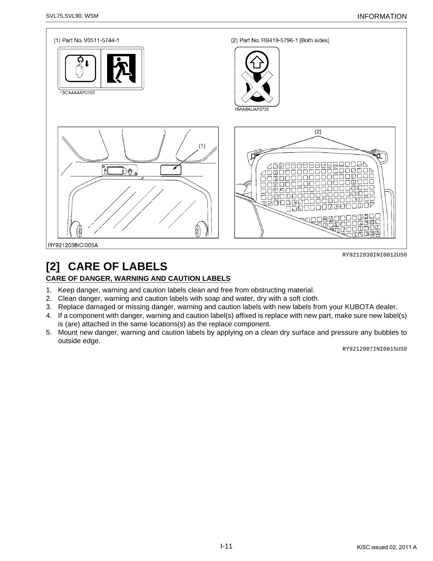
3. SAFETY DECALSp. 14
[1] LOCATIONSp. 14
[2] CARE OF LABELSp. 18
4. MAIN SPECIFICATIONSp. 19
5. DIMENSIONSp. 21
G GENERALp. 22
GENERALp. 23
1. MACHINE INDENTIFICATIONp. 24
2. ENGINE INDENTIFICATIONp. 25
[1] ENGINE NUMBERp. 25
[2] E3 ENGINEp. 26
[3] CYLINDER NUMBERp. 26
3. GENERAL PRECAUTIONSp. 27
4. HANDLING PRECAUTIONS FOR ELECTRICAL PARTS AND WIRINGp. 31
[1] WIRINGp. 31
[2] FUSESp. 35
[3] CONNECTORp. 35
[4] WASHING THE MACHINE WITH A HIGH-PRESSURE WASHERp. 37
5. LUBRICANTS, FUEL AND COOLANTp. 38
6. TIGHTENING TORQUESp. 39
[1] GENERAL USE SCREWS, BOLTS AND NUTSp. 39
[2] STUD BOLTSp. 39
[3] TORQUE FOR HYDRAULIC HOSE FITTINGSp. 40
(1) Torque for Hydraulic Hose Fittingsp. 40
(2) Torques of Lock-Nuts for Elbows with Male Seats and Adaptors with O-rings (Straight Threads)p. 41
(3) Torque for Tapering Adaptorsp. 41
[4] HOSE CLAMP SCREW TORQUEp. 42
7. MAINTENANCEp. 43
[1] MAINTENANCE INTERVALSp. 43
[2] OPENING AND CLOSING OF PARTSp. 46
[3] DAILY CHECKSp. 51
[4] REGULAR CHECKS AND MAINTENANCE WORKp. 58
(1) Every 50 Service Hoursp. 58
(2) Every 250 Service Hoursp. 61
(3) Every 500 Service Hoursp. 66
(4) Every 1000 Service Hoursp. 69
(5) Every 1500 Service Hoursp. 70
(6) Every 2000 Service Hoursp. 70
(7) Every 3000 Service Hoursp. 70
(8) Annual servicingp. 70
(9) Biennial Servicingp. 71
(10) Servicing as requiredp. 74
[5] OTHER ADJUSTMENTS AND REPLACEMENTSp. 75
(1) Purging of the Fuel Systemp. 75
(2) Adjustment of Tracksp. 75
(3) Fusesp. 76
8. SPECIAL TOOLSp. 79
1 ENGINEp. 97
MECHANISMp. 98
1. SVL 75 (V3307-DI-TE3-CTL)p. 100
[1] SPECIFICATIONSp. 100
[2] DIMENSIONSp. 100
[3] PERFORMANCE CURVESp. 101
[4] FEATUREp. 102
[5] ENGINE BODYp. 103
(1) CYLINDER BLOCKp. 103
(2) COOLING JACKETp. 103
(3) HALF-FLOATING HEAD COVERp. 104
(4) CYLINDER HEADp. 104
(5) 4 SCREWS PER EACH CYLINDER ASSEMBLING STRUCTUREp. 105
(6) CENTER DIRECT INJECTION SYSTEM (E-CDIS)p. 106
(7) GEAR TRAIN CONFIGURATIONp. 107
(8) PISTONp. 107
[6] LUBRICATING SYSTEMp. 108
(1) OIL COOLERp. 108
[7] COOLING SYSTEMp. 109
(1) THERMOSTATp. 109
(2) BOTTOM BYPASS SYSTEMp. 110
[8] FUEL SYSTEMp. 111
(1) GOVERNORp. 111
(2) 2 STAGE DI NOZZLEp. 113
(3) INJECTION PUMP WITH F.S.P.p. 114
(4) CPV EQUIPPED DELIVERY VALVEp. 115
[9] INTAKE AND EXHAUST SYSTEMp. 116
(1) TURBOCHARGERp. 116
[10] EXHAUST GAS RECIRCULATION (EGR) SYSTEMp. 117
(1) GENERALp. 117
(2) EXTERNAL MECHANICAL EGRp. 117
2. SVL 90 (V3800-DI-TE3-L6)p. 120
[1] SPECIFICATIONSp. 120
[2] DIMENSIONSp. 120
[3] PERFORMANCE CURVESp. 121
[4] FEATUREp. 122
[5] ENGINE BODYp. 123
(1) CYLINDER BLOCKp. 123
(2) HALF-FLOATING HEAD COVERp. 123
(3) CYLINDER HEADp. 124
(4) CENTER DIRECT INJECTION SYSTEM (E-CDIS)p. 124
(5) PISTONp. 125
[6] LUBRICATING SYSTEMp. 125
(1) OIL COOLERp. 125
[7] COOLING SYSTEMp. 126
(1) THERMOSTATp. 126
(2) BOTTOM BYPASS SYSTEMp. 127
[8] FUEL SYSTEMp. 128
(1) GOVERNORp. 128
(2) 2 STAGE DI NOZZLEp. 130
(3) INJECTION PUMP WITH F.S.P.p. 131
[9] TURBOCHARGER SYSTEMp. 132
(1) BOOST COMPENSATORp. 132
[10] INTAKE SYSTEMp. 132
(1) INTAKE AIR HEATERp. 132
[11] EXHAUST GAS RECIRCULATION (EGR) SYSTEMp. 133
(1) GENERALp. 133
SERVICINGp. 136
1. TROUBLESHOOTINGp. 137
2. SERVICING SPECIFICATIONp. 141
[1] SVL75p. 141
[2] SVL90p. 146
3. TIGHTENING TORQUES FOR SPECIAL USE SCREWS, BOLTS AND NUTS [SVL75]p. 151
4. TIGHTENING TORQUES FOR SPECIAL USE SCREWS, BOLTS AND NUTS [SVL90]p. 153
5. CHECKING, DISASSEMBLING AND SERVICINGp. 155
[1] CHECKING AND ADJUSTINGp. 155
(1) Engine Bodyp. 155
(2) Lubricating Systemp. 159
(3) Cooling Systemp. 160
(4) Fuel Systemp. 162
(5) Turbochargerp. 167
(6) EGR System [SVL75]p. 168
(7) EGR System [SVL90]p. 170
[2] DISASSEMBLING AND ASSEMBLINGp. 171
(1) Radiatorp. 171
(2) Muffler and muffler bracketp. 176
(3) Enginep. 179
(4) Turbochargerp. 201
(5) Exhaust Gas Recirculation (EGR)p. 202
(6) Cylinder Head and Valvesp. 203
(7) Thermostatp. 207
(8) Injection Pump Unitp. 208
(9) Water Pump and Oil Coolerp. 218
(10) Front Coverp. 218
(11) Flywheel and Timing Gearsp. 219
(12) Piston and Connecting Rodp. 222
(13) Crankshaft and Crankcasep. 226
[3] SERVICINGp. 228
(1) Cylinder Headp. 228
(2) Timing Gearsp. 237
(3) Piston and Connecting Rodp. 242
(4) Crankshaftp. 245
(5) Cylinderp. 251
(6) Oil Pumpp. 252
2 MACHINE BODYp. 253
SERVICINGp. 254
1. FRONTp. 255
[1] LIFT ARMp. 255
[2] LIFT ARM STOPPERp. 255
[3] LIFT ARM AND LINK 1 REMOVAL AND INSTALLATIONp. 256
[4] MECHANICAL QUICK HITCHp. 259
[5] HYDRAULIC QUICK HITCH (OPTION)p. 260
[6] FRONT PINS AND BUSHESp. 261
2. UPPER STRUCTUREp. 263
[1] CABIN (OPEN CABIN)p. 263
(1) Cabin Removal and Installationp. 266
[2] FUEL HOSE ROUTEp. 270
[3] FUEL TANKp. 273
(1) Fuel Tank Removal & Installationp. 275
[4] ACCELERATOR PEDAL – HAND ACCELERATORp. 279
(1) Accelerator Pedal and Hand Accelerator Removal and Installationp. 281
[5] CONTROL LEVER BRACKETp. 285
[6] ARMRESTp. 286
[7] SEAT AND SEATBELTp. 287
[8] REAR HOODp. 288
(1) Rear hood lockp. 289
(2) Rear Cover for Open Cab Model and Rear Hood Removal and Installationp. 290
3. TRACK FRAMEp. 292
[1] GREASE CYLINDERp. 292
[2] FRONT IDLER AND TENSIONER SPRINGp. 292
[3] REAR IDLERp. 293
[4] TRACK ROLLERp. 294
[5] SPROCKETp. 294
[6] RUBBER TRACKp. 295
(1) Rubber Crawler Removal and Installationp. 296
3 HYDRAULIC SYSTEMp. 298
MECHANISMp. 299
1. HYDRAULIC CIRCUITp. 301
[1] HYDRAULIC CIRCUIT [SVL75 MECHANICAL QUICK HITCH]p. 301
[2] HYDRAULIC CIRCUIT [SVL75 HYDRAULIC QUICK HITCH]p. 302
[3] HYDRAULIC CIRCUIT [SVL90 MECHANICAL QUICK HITCH]p. 303
[4] HYDRAULIC CIRCUIT [SVL90 HYDRAULIC QUICK HITCH]p. 304
[5] HYDRAULIC CIRCUIT [SVL90 MECHANICAL QUICK HITCH, HIGH-FLOW VERSION]p. 305
[6] HYDRAULIC CIRCUIT [SVL90 HYDRAULIC QUICK HITCH, HIGH-FLOW VERSION]p. 306
2. HYDRAULIC EQUIPMENT LAYOUTp. 307
[1] SVL75p. 307
[2] SVL90p. 308
3. HYDRAULIC SYSTEMp. 309
[1] OVERVIEWp. 309
[2] SAFETY EQUIPMENTp. 310
[3] SUCTION AND DELIVERY CIRCUITSp. 311
[4] RETURN AND DRAIN CIRCUITSp. 313
[5] FRONT OPERATION SYSTEMp. 314
(1) Overviewp. 314
(2) Flow of Oil when in Neutralp. 315
(3) Raising the Lift Arm Operationp. 316
(4) Lowering the Lift Arm Operationp. 324
(5) Bucket Crowd Operationp. 325
(6) Bucket Dump Operationp. 326
(7) Raising the Lift Arm and Dumping the Bucket Operationsp. 326
(8) Lowering the Lift Arm and Bucket Crowding Operationsp. 327
(9) AUX (Single Flow) Operationp. 328
(10) AUX (High-flow) Operations (SVL90 optional)p. 330
(11) Lift Arm Float Operationp. 332
(12) Hydraulic Quick Hitch (option)p. 337
[6] TRAVEL SYSTEMp. 338
(1) Forwardp. 338
(2) Backwardp. 340
(3) Swivel Left Operation (Spin Turn)p. 342
(4) Swivel Right Operation (Spin Turn)p. 344
(5) Forward Left Pivot Turnp. 346
(6) Charge Circuitp. 348
(7) Flushing Circuitp. 349
(8) Engine Stall Prevention Functionp. 350
(9) Travel 2-Speedp. 352
(10) Parking Brakep. 355
4. HST PUMPp. 356
[1] SPECIFICATIONSp. 356
[2] FUNCTION AND STRUCTUREp. 357
5. GEAR PUMPp. 359
[1] SPECIFICATIONSp. 359
[2] COMPONENTSp. 360
6. GEAR PUMP (HIGH-FLOW VERSION, SVL90 OPTION)p. 361
[1] SPECIFICATIONSp. 361
[2] COMPONENTSp. 362
7. TRAVEL CONTROL PILOT VALVEp. 363
[1] SPECIFICATIONSp. 363
[2] COMPONENTSp. 365
[3] FUNCTION AND STRUCTUREp. 366
(1) Functionp. 366
(2) Operationp. 366
8. FRONT CONTROL PILOT VALVEp. 368
[1] SPECIFICATIONSp. 368
[2] COMPONENTSp. 371
[3] FUNCTION AND STRUCTUREp. 372
(1) Functionp. 372
(2) Operationp. 372
9. CONTROL VALVEp. 373
[1] SPECIFICATIONSp. 373
[2] FUNCTION AND STRUCTUREp. 375
(1) Main relief valvep. 375
(2) Over load relief valvep. 376
10. TRAVEL MOTORp. 377
[1] SPECIFICATIONSp. 377
[2] FUNCTION AND STRUCTUREp. 378
11. LIFT ARM CYLINDERp. 379
[1] SPECIFICATIONSp. 379
[2] COMPONENTSp. 379
12. BUCKET CYLINDERp. 380
[1] SPECIFICATIONSp. 380
[2] COMPONENTSp. 380
13. HYDRAULIC QUICK HITCH CYLINDERp. 381
[1] SPECIFICATIONSp. 381
[2] COMPONENTSp. 381
14. UNLOAD VALVEp. 382
[1] SPECIFICATIONSp. 382
[2] COMPONENTSp. 383
15. AUX SOLENOID VALVEp. 384
[1] SPECIFICATIONSp. 384
16. QUICK HITCH SOLENOID VALVE (OPTION)p. 385
[1] SPECIFICATIONSp. 385
[2] COMPONENTSp. 386
17. HIGH-FLOW SOLENOID VALVE (SVL90 OPTION)p. 387
SERVICINGp. 389
1. TROUBLESHOOTINGp. 391
2. SERVICE DATAp. 400
3. PERFORMANCE CHECKS AND ADJUSTMENT METHODSp. 403
4. REMOVAL/INSTALLATION AND DISASSEMBLY/ASSEMBLYp. 415
[1] HST PUMPp. 415
(1) Joints Arrangement [SVL75]p. 415
(2) Joints Arrangement [SVL90 STD-Flow version]p. 416
(3) Joints Arrangement [SVL90 High-Flow version]p. 417
(4) Removal and Installationp. 418
(5) Dis/Assembly of the HST Pumpp. 422
(6) Pump couplingp. 453
(7) Special Toolsp. 455
[2] CONTROL VALVEp. 457
(1) Joints Arrangement [SVL75]p. 457
(2) Joints Arrangement [SVL90]p. 458
(3) Removal and Installationp. 459
(4) Control Valve Dis/Assemblyp. 460
[3] TRAVEL PILOT VALVE, FRONT OPERATION PILOT VALVEp. 480
(1) Joints Arrangementp. 480
(2) Removal/installationp. 481
(3) Dis/assembly procedurep. 483
(4) Special Tools (SVL75, SVL90 Combination)p. 492
[4] TRAVEL MOTORp. 493
(1) SVL75p. 493
(2) SVL90p. 496
(3) Joints Arrangement [SVL75]p. 499
(4) Joints Arrangement [SVL90]p. 500
(5) Removal and Installationp. 501
(6) Travel Motor Disassembly and Assembly Procedurep. 503
(7) Special Toolsp. 529
[5] LIFT ARM CYLINDERp. 536
(1) Removal/installationp. 536
(2) Hydraulic Cylinder Disassembly and Assemblyp. 539
(3) Special toolsp. 551
[6] BUCKET CYLINDERp. 562
(1) Removal/installationp. 562
(2) Hydraulic Cylinder Disassembly and Assemblyp. 563
[7] UNLOAD VALVEp. 564
(1) Joints Arrangement [SVL75]p. 564
(2) Joints Arrangement [SVL90 Mechanical Hitch Version]p. 565
(3) Joints Arrangement [SVL90 Hydraulic Hitch Version]p. 566
(4) Joints Arrangement [SVL90 Mechanical Hitch and High-Flow Version]p. 567
(5) Joints Arrangement [SVL90 Hydraulic Hitch and High-Flow Version]p. 568
(6) Removal and Installationp. 569
[8] AUX PROPORTIONAL CONTROL SOLENOIDp. 571
(1) Joints Arrangement [SVL75]p. 571
(2) Joints Arrangement [SVL90]p. 572
(3) Removal and Installationp. 573
[9] HYDRAULIC QUICK HITCH CONTROL SOLENOID (OPTION)p. 574
(1) Joints Arrangement [SVL75]p. 574
(2) Joints Arrangement [SVL90]p. 575
[10] HIGH-FLOW CONTROL SOLOENOID (SVL90 OPTION)p. 576
(1) Joints Arrangementp. 576
[11] HYDRAULIC OIL TANKp. 577
(1) Joints Arrangement [SVL75]p. 577
(2) Joints Arrangement [SVL90]p. 579
(3) Removal and Installationp. 581
5. HYDRAULIC PIPINGp. 585
[1] HYDRAULIC HOSE DIAGRAM [SVL75]p. 585
[2] TABLE OF HOSES [SVL75]p. 589
[3] HYDRAULIC HOSE DIAGRAM [SVL90]p. 592
[4] TABLE OF HOSES [SVL90]p. 596
4 ELECTRICAL SYSTEMp. 599
SERVICINGp. 600
1. DIAGNOSING MALFUNCTIONSp. 602
[1] OVERVIEW OF MALFUNCTION DIAGNOSISp. 602
[2] STEPS IN DIAGNOSING MALFUNCTIONSp. 602
[3] TESTING WITH A CIRCUIT TESTERp. 603
2. WIRING CIRCUITp. 605
[1] PRECAUTIONS ON HOW TO CLAMP THE ELECTRICAL WIRINGp. 605
[2] PRECAUTIONS ON HANDLING ELECTRICAL CONNECTORSp. 605
3. ELECTRONIC EQUIPMENT LAYOUTp. 606
[1] SVL75p. 606
[2] SVL90p. 607
4. UNPLUGGING ELECTRICAL CONNECTORS AND WIRING LAYOUTp. 608
[1] SVL75 ROPS/CAB AND AIR CONDITIONER VERSIONp. 608
[2] SVL90 ROPS/CAB AND AIR CONDITIONER VERSIONp. 632
5. TERMINAL NAMES OF THE MAIN CONNECTORp. 658
6. TROUBLESHOOTING (START-UP EQUIPMENT VERSION)p. 660
7. INSPECTIONSp. 661
[1] BATTERY POWERp. 661
[2] STARTING EQUIPMENTp. 665
[3] LAYOUT OF RELAYS AND FUSESp. 666
(1) SVL75 Rops Versionp. 666
(2) SVL75 Cab and Air conditioner Versionp. 668
(3) SVL90 Rops/Cab and Air conditioner Versionp. 670
[4] STOPPING EQUIPMENTp. 672
8. INSTRUMENT PANELp. 674
[1] PANEL FUNCTIONSp. 674
(1) Lamp Displaysp. 674
(2) Warning lampp. 674
(3) Buzzer Soundsp. 674
[2] USER MODEp. 675
(1) What is the user mode?p. 675
(2) Warning lamp displaysp. 675
[3] SERVICE MODEp. 677
(1) What is the service mode?p. 677
(2) Entering the Service Modep. 678
(3) Using the Service Modesp. 679
9. TROUBLESHOOTING (INSTRUMENT PANEL EDITION)p. 688
[1] 5V SHORT SYSTEM ERRORSp. 688
(1) Checking via the Panel Displayp. 688
(2) Inspecting each Device Visually and Physicallyp. 688
(3) Testing the Equipment Itselfp. 690
[2] OVER VOLTAGE ERRORSp. 691
(1) Checking via the Panel Displayp. 691
(2) Testing with a Circuit Testerp. 692
[3] PARKING BRAKE SOLENOID AND TRAVEL LOCK SOLENOID ERRORSp. 693
(1) Checking via the Panel Displayp. 693
(2) Inspecting each Device Visually and Physicallyp. 695
(3) Testing with a Circuit Testerp. 696
(4) Testing the Equipment Itselfp. 698
[4] HYDRAULIC QUICK-HITCH SOLENOID ERRORSp. 700
(1) Checking via the Panel Displayp. 700
(2) Inspecting each Device Visually and Physicallyp. 702
(3) Testing with a Circuit Testerp. 703
(4) Testing the Equipment Itselfp. 704
[5] HIGH-FLOW SOLENOID ERROR (SVL90)p. 706
(1) Checking via the Panel Displayp. 706
(2) Inspecting each Device Visually and Physicallyp. 708
(3) Testing with a Circuit Testerp. 709
(4) Testing the Equipment Itselfp. 710
[6] FLOAT SOLENOID ERRORp. 712
(1) Checking via the Panel Displayp. 712
(2) Inspecting each Device Visually and Physicallyp. 714
(3) Testing with a Circuit Testerp. 715
(4) Testing the Equipment Itselfp. 717
[7] FRONT CONTROL LOCK SOLENOID ERRORSp. 719
(1) Checking via the Panel Displayp. 719
(2) Inspecting each Device Visually and Physicallyp. 720
(3) Testing with a Circuit Testerp. 721
(4) Testing the Equipment Itselfp. 722
[8] TRAVEL HIGH-LOW SWITCH SOLENOID ERRORSp. 724
(1) Checking via the Panel Displayp. 724
(2) Inspecting each Device Visually and Physicallyp. 726
(3) Testing with a Circuit Testerp. 727
(4) Testing the Equipment Itselfp. 728
[9] AUX KNOB ERRORSp. 730
(1) Checking via the Panel Displayp. 730
(2) Inspecting each Device Visually and Physicallyp. 731
(3) Testing with a Circuit Testerp. 732
(4) Testing the Equipment Itselfp. 734
[10] AUX RIGHT SOLENOID ERRORSp. 735
(1) Checking via the LCD Panel Displayp. 735
(2) Inspecting each Device Visually and Physicallyp. 737
(3) Testing with a Circuit Testerp. 738
(4) Testing the Equipment Itselfp. 739
[11] AUX LEFT SOLENOID ERRORSp. 741
(1) Checking via the Panel Displayp. 741
(2) Inspecting each Device Visually and Physicallyp. 743
(3) Testing with a Circuit Testerp. 744
(4) Testing the Equipment Itselfp. 745
[12] ENGINE OIL PRESSURE ERRORSp. 747
(1) Checking via the Panel Displayp. 747
(2) Inspecting each Device Visually and Physicallyp. 748
(3) Testing with a Circuit Testerp. 749
(4) Testing the Equipment Itselfp. 751
[13] HYDRAULIC TEMPERATURE SENSOR ERRORSp. 752
(1) Checking via the Panel Displayp. 752
(2) Inspecting each Device Visually and Physicallyp. 753
(3) Testing with a Circuit Testerp. 754
(4) Testing the Equipment Itselfp. 756
[14] WATER TEMPERATURE SENSOR OVERHEATING ERRORSp. 757
(1) Checking via the Panel Displayp. 757
(2) Inspecting each Device Visually and Physicallyp. 758
(3) Testing with a Circuit Testerp. 759
(4) Testing the Equipment Itselfp. 761
10. BLOCK DIAGRAM OF METERp. 762
5 CABINp. 763
MECHANISMp. 764
1. AIR CONDITIONING SYSTEMp. 765
[1] STRUCTUREp. 765
[2] HOW THE MECHANISMS OF THE SYSTEM WORKp. 767
[3] COMPRESSORp. 768
[4] AIR CONDITIONING UNITp. 771
[5] CONDENSERp. 776
[6] RECEIVERp. 777
[7] PRESSURE SWITCHp. 778
[8] SYSTEM CONTROLSp. 779
[9] ADJUSTING THE AIR FLOW AND DIRECTIONp. 780
[10] ELECTRICAL SYSTEMp. 781
(1) Electrical Circuitsp. 781
(2) Relaysp. 782
2. WIPERp. 783
[1] WIPER SWITCHp. 783
[2] WIPER MOTORp. 783
SERVICINGp. 784
1. TROUBLESHOOTINGp. 786
2. MAINTENANCE AND SERVICE RELATED SPECIFICATIONSp. 789
3. TORQUEp. 790
4. PRECAUTIONS WHEN REPAIRING THE REFRIGERANT SYSTEMp. 791
[1] USE OF SERVICE TOOLSp. 791
(1) Manifold Gauge Setp. 791
(2) Refrigerant charging hosesp. 793
(3) Vacuum Pump Adapterp. 794
(4) Electric Gas Leak Testerp. 794
(5) Canister Tap Valvep. 794
(6) T-Jointp. 795
(7) R134a Refrigerant Collection/Recycling Devicep. 795
5. INSPECTING AND CHARGING THE REFRIGERANT SYSTEMp. 796
[1] CHECKING THE SYSTEM WITH A MANIFOLD GAUGEp. 796
[2] COLLECTION, VACUUMING AND CHARGINGp. 801
(1) Collecting Refrigerantp. 801
(2) Vacuuming out the Systemp. 802
[3] CHARGING FROM THE HIGH-PRESSURE SIDEp. 803
[4] CHARGING FROM THE LOW-PRESSURE SIDEp. 804
6. INSPECTION AND DISASSEMBLYp. 805
[1] CHECKS AND ADJUSTMENTSp. 805
(1) Compressorp. 805
(2) Relaysp. 806
(3) Blower motorp. 808
(4) Blower resistorp. 809
(5) Fan Switchp. 810
(6) Pressure Switchp. 812
[2] Disassembly and Assemblyp. 813
(1) Removal and Installation of the AC Unitp. 813
(2) Mounting and Removing the Compressorp. 814
(3) Removal and Installation of the Cablep. 817
(4) Connecting/Disconnecting AC Hosesp. 819
(5) AC Hose Routingp. 824
(6) Removal and Installation of Heater Hosesp. 828
(7) Heater Hose Routingp. 832
(8) Installation and Removal of the Condenserp. 836
(9) Installation and Removal of the Receiver-drierp. 837
(10) Installation and Removal of the Fanp. 838
(11) Installation and Removal of Coversp. 839
(12) Windshield Removal and Installationp. 840
7. WINDOW WASHERp. 852
[1] WIPER SWITCHp. 852
[2] WIPER MOTORp. 853
[3] WASHER MOTORp. 853
8. REMOVAL AND INSTALLATION OF GLASSp. 854
[1] PREPARATIONp. 854
[2] REMOVING GLASSp. 855
[3] INSTALLING WINDOWSp. 856
(1) Moonroofp. 856
(2) Rear Windowp. 857
(3) Installation and Removal of Right and Left Windowsp. 860
[4] INSTALLING THE TRIMp. 862
9. LIGHTING EQUIPMENTp. 863
10. HYDRAULIC HOSE ROUTINGp. 864
ELECTRICAL CIRCUIT DIAGRAMp. 866

Taken together, this document gives a technician everything needed to move from initial fault diagnosis through full teardown and reassembly on either the SVL75 or the SVL90, without needing to cross-reference a second source for structural, hydraulic, or electrical work.

What You Can Do With This Manual

The Kubota SVL75 SVL90 workshop manual walks through hydraulic pump and valve servicing, HST and gear pump rebuilds, lift arm and bucket cylinder overhaul, track frame and undercarriage repair, full electrical system troubleshooting with wiring circuits and connector layouts, and cabin/HVAC servicing including refrigerant system precautions. Tightening torque tables, service data, and performance-check procedures are specific to each model, so whether you’re working on a Standard-Flow SVL75 or a High-Flow SVL90, the correct specification is in front of you rather than approximated from a similar machine.

IMAGES PREVIEW

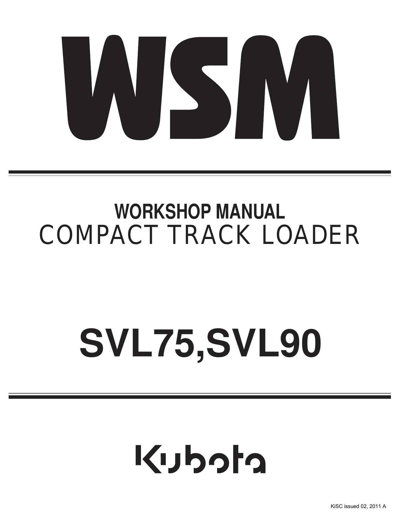
Kubota SVL75 SVL90 Compact Track Loader Workshop Service Manual (2011) PDF Download β€” PDF page 1 preview
Kubota SVL75 SVL90 Compact Track Loader Workshop Service Manual (2011) PDF Download β€” PDF page 15 preview
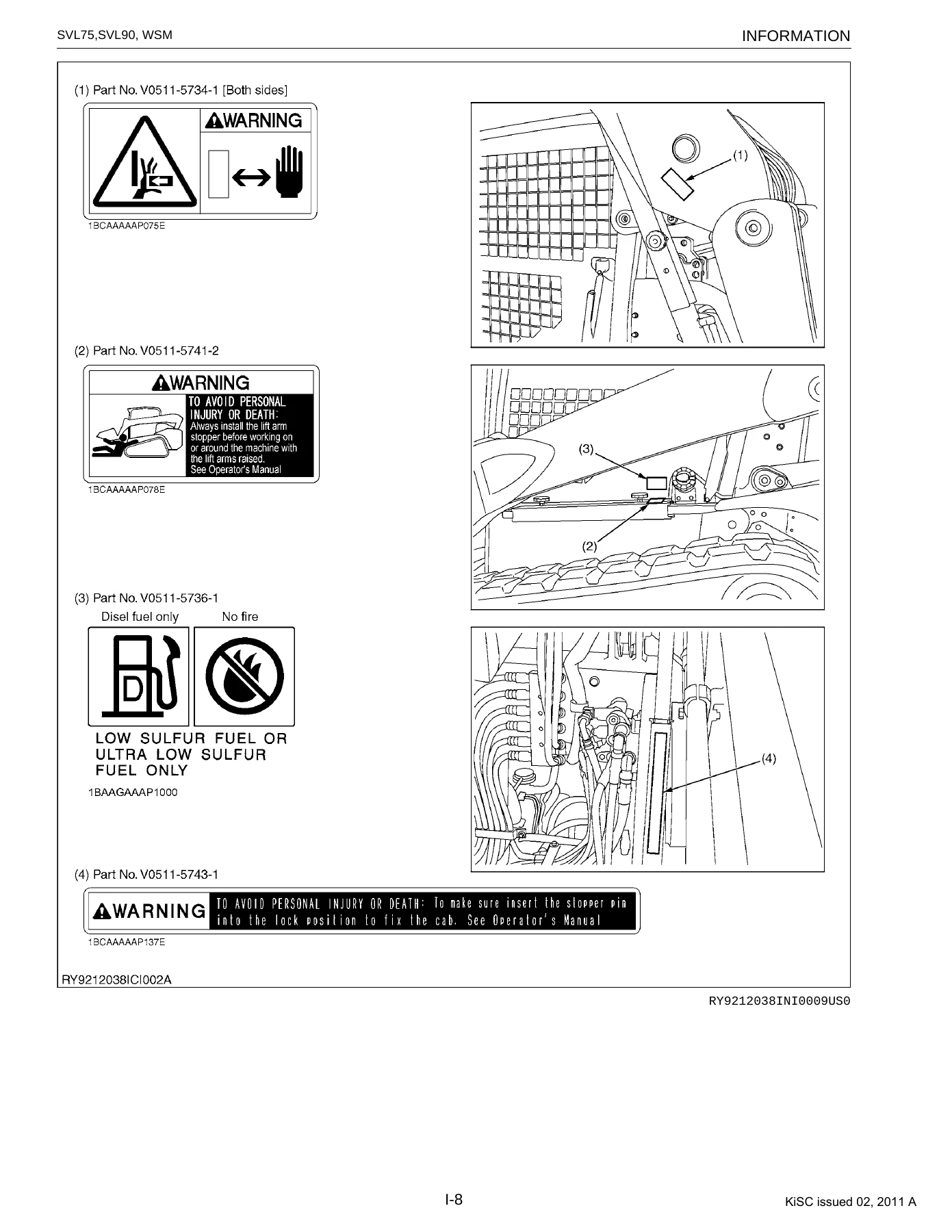
Kubota SVL75 SVL90 Compact Track Loader Workshop Service Manual (2011) PDF Download β€” PDF page 18 preview

Why This Manual Matters

Compact track loaders see hard, repetitive cycles — hydraulic circuits, track frames, and electrical connectors take the brunt of it. Using the correct torque values, hydraulic pressures, and disassembly sequence for the SVL75 or SVL90 specifically protects against comebacks, leaks, and premature component wear that come from guessing at specs. This Kubota SVL75 SVL90 service manual keeps every procedure tied to the exact engine and hydraulic configuration fitted to your machine.

Delivered instantly as a PDF after purchase — no shipping, no waiting. Read it on a laptop, tablet, or phone in the shop, or print the sections you need. This Kubota SVL75 SVL90 workshop manual stays on your device for reference on every job, from routine maintenance to full hydraulic and electrical diagnostics.

Reviews

There are no reviews yet.

Be the first to review “Kubota SVL75 SVL90 Compact Track Loader Workshop Service Manual (2011) PDF Download”

What Our Customers Say

β˜…β˜…β˜…β˜…β˜… Live reviews from customers
Loading customer reviews...
0
    0
    Your Cart
    Your cart is emptyReturn to Shop
    πŸ›’
    Recently Purchased
    πŸ•’ verified order