
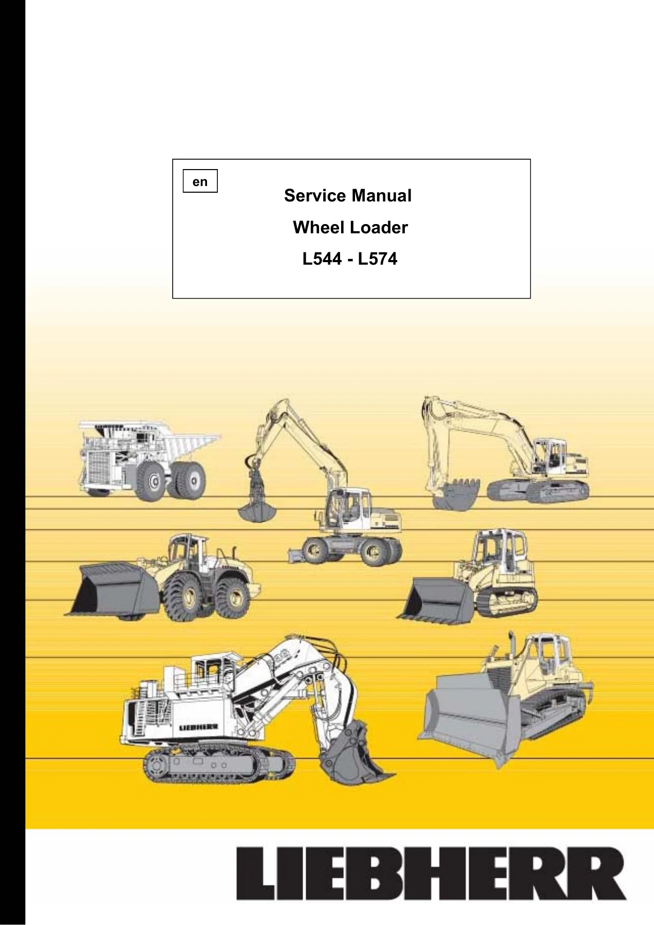
Liebherr L544 L554 L564 L574 Wheel Loader Service Manual 1999 PDF Download
Original price was: $74.95.$49.95Current price is: $49.95.
Complete 658-page Liebherr service manual for L544, L554, L564 and L574 wheel loaders. Covers diesel engine, hydraulics, electrical, axles, transfer gear, maintenance and service codes. Instant PDF download.
Description
This Liebherr L544 L554 L564 L574 Wheel Loader Service Manual 1999 PDF Download is the complete 658-page service manual for the Liebherr L544, L554, L564 and L574 wheel loaders. It is written for mechanics, workshop specialists and maintenance technicians who need the correct procedures, hydraulic pressures, electrical references and component data for these machines. The manual is in English and covers the major systems from the diesel engine and pump distributor gear through to the cab, lift arm and attachments. Whether you are servicing a single machine or running a fleet, this Liebherr wheel loader service manual gives you the technical depth to work accurately.
File Details
- Manual type: Service Manual
- Brand: Liebherr
- Models covered: L544, L554, L564, L574
- Document title: Wheel Loader Service Manual L544 – L574
- Issue: 05.1999
- Order number: 8450616
- Language: English
- Page count: 658
- File format: PDF
Chapters Covered
- 1 General information
- 2 Technical data
- 3 Maintenance
- 4 Diesel engine, Pump distributor gear
- 5 Cooling system
- 6 Travel hydraulics
- 7 Working hydraulics
- 8 Steering system
- 9 Brake system
- 10 Electrical system
- 11 Transfer gear
- 12 Axles, Tyres
- 13 Vehicle frame, Ballast weight
- 14 Central lubrication system
- 15 Covering, Cab access
- 16 Cab, Heating, Air conditioning system
- 17 Lift arm, Quick change device
- 18 Attachments, Accessories
- 19.2 Service codes and warning signals
General Information and Technical Data
1 General information
Safety regulations, special tools for maintenance and repair work, plus the tool identification numbers you need for electrics, Liebherr diesel engines, hydraulic cylinders and ZF axles. This section is where the manual sets out the working instructions and safety precautions that apply across the whole machine.
2 Technical data
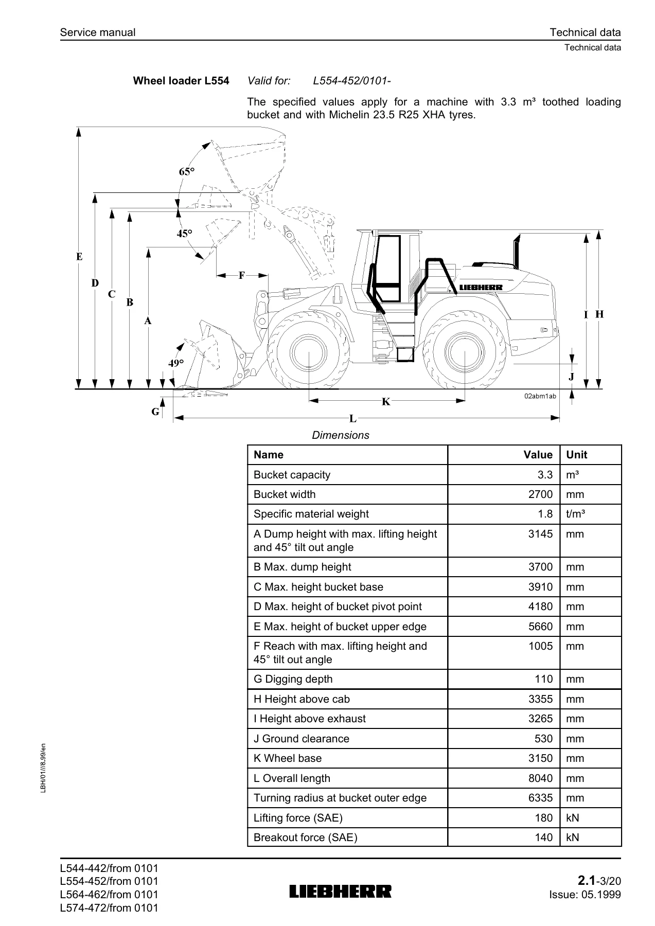
Complete machine dimensions and working data for each model, including bucket capacities, dump heights, tipping loads, operating weights and travel speeds. It also contains technical data for the diesel engine, pump distributor gear, cooling system, travel hydraulics, working hydraulics, steering, brakes, electrical system, transfer gear, axles, tyres, cab, lift arm and attachments.
3 Maintenance
The maintenance and inspection schedule, lubrication chart and filling quantity tables. It explains daily, weekly, 500-hour, 1000-hour and 2000-hour maintenance tasks, plus unscheduled maintenance. Lubricant and fuel specifications are also covered, including diesel engine oils, hydraulic oils, transmission oils, greases and coolants.
Engine, Cooling and Hydraulics
4 Diesel engine, Pump distributor gear
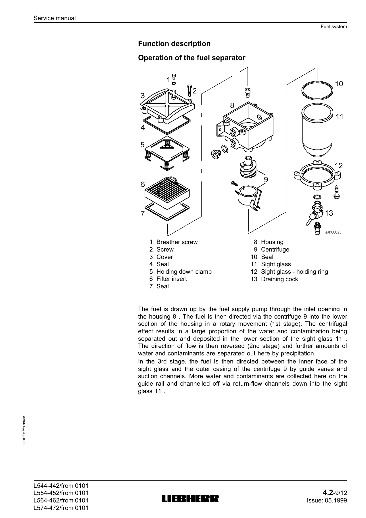
Design and function of the installed Liebherr diesel engines, including the D924T-E A2, D924TI-E A2 and D926TI-E A2. Covers electrical components, speed sensor, fuel system, fuel level sensors, fuel separator, refuelling pump, air filter system, torsion absorber coupling and pump distributor gear. Technical data and function descriptions are provided for each assembly.
5 Cooling system
The hydrostatically driven fan, gear pump, gear motor, proportional pressure relief valve and temperature sensors. It explains fan speed control, system pressures, fail-safe function and cooling system technical data for the different model groups.
6 Travel hydraulics
The closed-circuit hydrostatic travel drive, variable displacement pump, variable displacement motor, replenishing pump, pressure cut-off, inching function, creeper function and gear pump for motor housing scavenging. It includes detailed hydraulic circuit diagrams, component sections and adjustment data.
7 Working hydraulics
The variable displacement pump with flow, pressure and power controllers, the control valve block, pilot control unit, ride control, stabilization module, hydro accumulator unit, lift cylinder, tilt cylinder and hydraulic tank. It covers load sensing, pressure relief valves, float position, quick drop function, housing pre-heating and technical specifications.
Steering, Brakes and Electrical
8 Steering system
The steering pump, servostat, steering cylinders, hydro accumulators, emergency steering pump, valve block and pressure switches. It explains the load sensing steering circuit, emergency steering function and the automatic safety test that runs when the engine is started.
9 Brake system
The hydraulic double-circuit service brake with wet disc brakes in the wheel hubs, the compact brake valve, accumulator charging function, parking brake and spring-loaded caliper brake. Test connection pressures and technical data are included for the brake accumulators, pressure switches and parking brake gap adjustment.
10 Electrical system
Complete electrical component lists, circuit diagram steps 1 to 18, control electronics, control board, control unit, display unit, fuses, relays, connectors and wiring harness references. It covers engine monitoring, lighting, wipers, air conditioning, parking brake, ride control, working hydraulics lockout and optional functions.
Drivetrain, Axles and Frame
11 Transfer gear
The mechanical transfer gear with powershift section and final drive, electronic control unit, electro-hydraulic pressure modulation, gear pump, in-line filter and shift pressure data. It explains gear shifting, pressure modulation, reverse travel, tractive force adjustment, overspeed protection and error code functions.
12 Axles, Tyres
Front and rear axle design, self-locking differential, planetary wheel hub drives, wet disc service brakes, wheel hub bearings, drive shafts and tyre references. Technical data includes axle ratios, locking values, wheel lug tightening torque, track widths and drive shaft lengths.
13 Vehicle frame, Ballast weight
The front and rear frame sections, articulation bearing, oscillating bearing, articulation lock and ballast weight. It covers the basic function of the frame and the mounting points that carry the engine, cab, transfer gear and axles.
Lubrication, Cab, Lift Arm and Attachments
14 Central lubrication system
Manual central lubrication rails and the automatic central lubrication system with EP-1 pump, progressive distributor MX-F and control unit S-EP4. It explains progressive lubrication, lubrication and pause times, safety functions and lubrication point overviews.
15 Covering, Cab access
The covering sections including mud guards, wheel boxes, engine cover, rear cover, lower coverings, side covers, cooler hood and front cover. It also covers cab access, handrails and the tool box.
16 Cab, Heating, Air conditioning system
Control panel, display unit, control element, control unit, LIEBHERR control lever, heating and ventilation, air conditioning system, compressor, condenser, dryer-collector unit, pressure switch and evaporator. It includes heating output, refrigerant type R134a, blower data and air conditioning pressures.
17 Lift arm, Quick change device
Lift arm lengths for L544, L554, L564 and L574, Z-bar kinematics, bucket bearing and pin bearing sealing. It explains the lift arm and bucket movements, bearing sealing design and the axial play specification.
18 Attachments, Accessories
Loading buckets from 2.8 m³ to 4.5 m³ and optional forklift attachments with 1500 mm or 1800 mm prongs. Main dimensions, masses and toothing details are provided for each attachment.
19.2 Service codes and warning signals
The service code and warning signal tables for the gear electronics and machine monitoring. It lists error codes, effects, possible causes and remedies, plus audible and visible warning signals for coolant temperature, hydraulic oil temperature, emergency steering, engine oil pressure, brake accumulator pressure and gear oil temperature.
Why This Liebherr L544 L554 L564 L574 Service Manual Matters
This Liebherr wheel loader service manual is a deep technical reference for the L544, L554, L564 and L574. It supports real workshop jobs: checking hydraulic pressures, adjusting travel pump regulation, diagnosing service codes, testing brake accumulators, replacing filters and oils, setting valve play, servicing the transfer gear and understanding the electrical circuit diagrams. The procedures and values are presented by system, so you can move from a fault symptom to the correct test connection, pressure value, torque or adjustment specification. Correct procedures and accurate specifications reduce guesswork, prevent damage to pumps, cylinders, brakes and electronics, and help keep these heavy wheel loaders working reliably.
IMAGES PREVIEW
Delivery is instant. After payment, the PDF is available to download immediately, with no shipping and no waiting. You can use it on a laptop, tablet or phone, print the pages you need for the workshop, and keep the complete 658-page Liebherr L544 L554 L564 L574 service manual on hand for daily maintenance, repairs and troubleshooting.
Reviews
There are no reviews yet.