★ TRUSTED BY 321,897+ PROFESSIONALS WORLDWIDE
🏒
Trusted Business
Verified & Licensed
πŸ›‘οΈ
Virus Free Files
100% Safe Downloads
πŸ”’
Secure Payment
SSL Protected
⚑
Instant Delivery
Available Immediately
Sale!

Liugong CLG385B Skid Steer Loader Service Manual – YANMAR 4TNV98CT Engine

Original price was: $39.95.Current price is: $24.95.

Complete 515-page service manual for the Liugong CLG385B skid steer loader with YANMAR 4TNV98CT engine. Covers engine, hydraulics, electrical, cab, drive system, and A/C. Instant PDF download.

⚑
Instant PDF Download
Available immediately
πŸ’Ύ
Save to Your Device
Download & keep forever
πŸ›‘οΈ
Antivirus Scanned
100% virus-free
🌍
Trusted Worldwide
175,000+ customers

Description

Liugong CLG385B Skid Steer Loader Service Manual

This is the complete service manual for the Liugong CLG385B skid steer loader equipped with the YANMAR 4TNV98CT engine. Published under document number 201606001, this 515-page manual provides technicians and owners with full repair, maintenance, and diagnostic procedures for every major system on the machine. Whether you are servicing the engine, troubleshooting the electrical system, rebuilding hydraulic components, or adjusting the drive chains, this manual gives you the step-by-step guidance and specifications needed to get the job done correctly.

File Details

  • Manual type: Service Manual
  • Brand: Liugong
  • Model: CLG385B
  • Engine: YANMAR 4TNV98CT
  • Document number: 201606001
  • Date: June 15, 2016
  • Language: English
  • Page count: 515
  • File format: PDF

Chapters Covered

  • General Information β€” Oil and lubrication tables, standard torque parameters, unit conversion tables, safety instructions
  • Engine System β€” Removal and installation of engine and radiator, radiator system, coupling, engine maintenance
  • Sprocket Drive System β€” Hub components, spindle, tire rim, chain adjustment, sprocket box oil level
  • Electrical System β€” System layout, cab wiring, frame and engine wiring, rear hood wiring, removal and installation of electrical components, troubleshooting, battery, starter motor, alternator, relay, ignition switch, disconnect switch, sensors, lights, horn, wiper, radio
  • Driver’s Cab β€” Cab removal and installation, rear window, side window, roof window, front door, seat, handrail, components removal and assembly
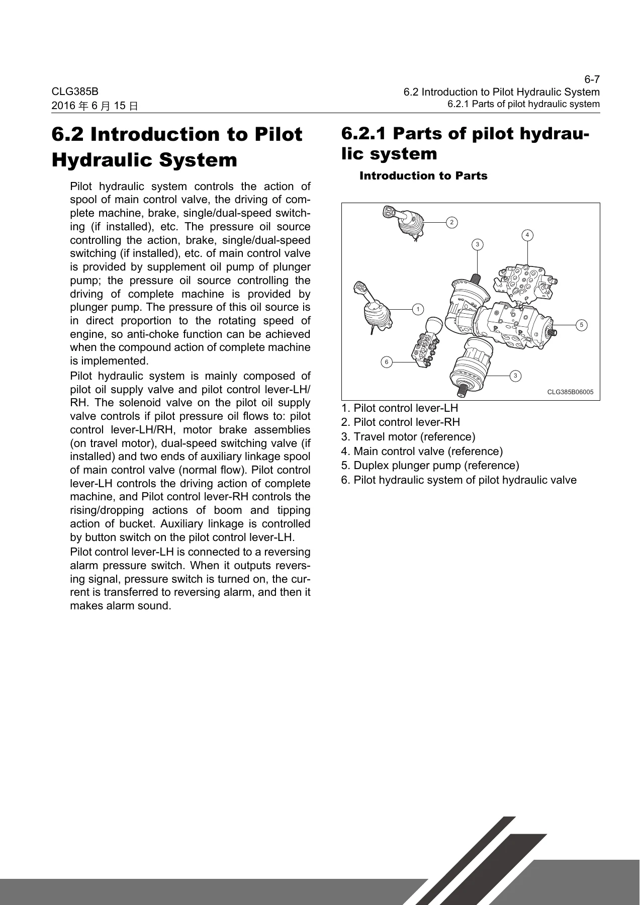
  • Hydraulic System β€” Pilot hydraulic system, working hydraulic system, travel hydraulic system, system testing, cleaning, troubleshooting, removal and installation of work, pilot, and travel hydraulic components
  • Covering Parts β€” Removal and mounting of covers, engine hood removal and installation
  • Boom and Quick Coupler β€” Removal and installation procedures
  • A/C System (If Equipped) β€” Fault diagnosis, maintenance, refrigerant recovery, vacuuming and charging, removal and installation of compressor, evaporator, condenser, and reservoir bottle

This Liugong CLG385B service manual is structured for practical use in the workshop. Each chapter opens with component identification and system overviews before walking through removal, inspection, assembly, and installation sequences. Torque values, pressure settings, and adjustment tolerances are embedded directly in the procedures, so you are not hunting through separate specification sheets. The electrical section is especially detailed, with pin definitions, wiring schematics, fuse box layouts, and troubleshooting flowcharts for the battery, starter, alternator, relays, and all major switches. The hydraulic section covers pilot, working, and travel circuits with complete disassembly and reassembly instructions for the plunger pump, travel motor, main control valve, gear pumps, and cylinders, plus pressure and flow test procedures. Whether you are a professional technician or a hands-on owner, this CLG385B service manual gives you the information needed to service the machine safely and correctly.

What You Can Do With This Manual

The Liugong CLG385B service manual supports a wide range of repair and maintenance tasks. You can remove and reinstall the engine and radiator, rebuild the coupling, service the sprocket drive system including chain tension adjustment and sprocket box oil changes, diagnose electrical faults using the detailed wiring schematics and pin-out tables, remove and install the cab and all its components, overhaul the hydraulic system from pilot control levers to the travel motor and main control valve, adjust the boom and quick coupler, and service the air conditioning system including refrigerant recovery and recharge. The manual also includes complete torque specifications, system pressure values, flow rates, and service limits so you can verify your work against factory requirements.

Why This Manual Matters

Working on a skid steer loader without the correct service information risks damaging expensive components or creating unsafe operating conditions. The CLG385B is a complex machine with interlocked safety systems, electronically controlled engine functions, and high-pressure hydraulic circuits. The procedures in this manual reflect the specific design of the CLG385B and YANMAR 4TNV98CT engine, including the correct tightening sequences, seal installation directions, and adjustment values that generic repair guides will not provide. Having the actual service manual means you can complete repairs with confidence, avoid comebacks, and keep the machine running at its best.

Complete PDF Bookmark Tree

Complete Bookmarks

The complete bookmarks in the β€œLiugong CLG385B Skid Steer Loader Service Manual – YANMAR 4TNV98CT Engine” are as follows:

1 General Informationp. 5
1.1 Oil & Lubrication Tablep. 7
1.1.1 Engine lubricationp. 7
1.2 Suggestion of Standard Torque Parametersp. 11
1.2.1 Bolt, nut and stud in grade 12.9p. 12
1.2.2 Standard torque of nut for the hose connectorp. 12
1.3 Unit Conversion Tablep. 15
1.4 Safety Instructionp. 17
1.4.1 Safety warning symbolsp. 17
1.4.2 Words on safety signp. 17
1.4.3 General safety precautionsp. 18
1.4.4 Safety operation of machinep. 26
1.4.5 Safety maintenance for the machinep. 30
2 Engine Systemp. 33
2.1 Removal and Installation of Engine and Radiatorp. 39
2.1.1 Radiator systemp. 39
2.1.2 Radiator system disassemblingp. 39
2.1.3 Radiator System Installationp. 41
2.2 Engine Systemp. 43
2.2.1 Removal and installation of the enginep. 43
2.2.2 Installation of the enginep. 50
2.3 Couplingp. 57
2.3.1 Torque listp. 57
2.3.2 The removal of couplingp. 57
2.3.3 Checkp. 58
2.3.4 Assembly of couplingp. 58
2.3.5 Engine maintenancep. 58
3 Sprocket Drive Systemp. 59
3.1 Sprocket Drive Systemp. 61
3.1.1 System diagram of hub componentsp. 61
3.1.2 Tool listp. 61
3.1.3 Removal of sprocket drive systemp. 61
3.1.4 Installation of sprocket drive systemp. 64
3.2 Spindlep. 68
3.2.1 Torque specificationsp. 68
3.2.2 Wheel components diagramp. 68
3.2.3 Spindle cutaway viewp. 68
3.2.4 Spindle diagramp. 68
3.2.5 Inspection of Spindlep. 69
3.2.6 Assembly of spindle bearing components.p. 69
3.3 Tire Rimp. 72
3.3.1 Tire pressurep. 72
3.3.2 Tire inflationp. 72
3.3.3 Torque of rim nut of tirep. 72
3.4 Adjustment of Chainp. 73
3.4.1 Check tension of transmission chainp. 73
3.4.2 Adjust tension of transmission chainp. 74
3.5 Oil Adjustment of Sprocket Boxp. 75
3.5.1 Oil check of sprocket boxp. 75
3.5.2 Oil Adjustment of Sprocket Boxp. 75
4 Electrical Systemp. 77
4.1 Overview of Electrical systemp. 79
4.1.1 Instructionsp. 79
4.1.2 Precautions for maintenancep. 79
4.1.3 Operation instruction of digital multimeterp. 80
4.1.4 Introduction to electrical systemp. 81
4.2 Basics Introduction of the Electrical System Layoutp. 88
4.2.1 Cab wiring assemblyp. 88
4.2.2 Frame and engine wiring assemblyp. 89
4.2.3 Position of the rear hood wiring assemblyp. 90
4.2.4 Audio system (if equipped)p. 91
4.2.5 Relay assemblyp. 91
4.3 How to Use Machinep. 92
4.3.1 Allow start lockp. 92
4.3.2 Travel and boom bucket unlockp. 92
4.4 Removal and Installation of Electrical Componentsp. 93
4.4.1 Chassis Harness As.p. 93
4.4.2 Engine wiring assemblyp. 112
4.4.3 Cab wiring assemblyp. 119
4.5 Description and Troubleshooting of the Electrical Systemp. 130
4.5.1 General informationp. 130
4.6 Introduction to the Definition of Function of Electrical Unit and Common Fault Analysisp. 140
4.6.1 Batteryp. 140
4.6.2 Starter motorp. 143
4.6.3 Alternatorp. 146
4.6.4 Relayp. 149
4.6.5 Ignition switchp. 153
4.6.6 Disconnect switchp. 154
4.6.7 Door switchp. 155
4.6.8 Hydraulic oil temperature alert switchp. 155
4.6.9 Fuel sensorp. 156
4.6.10 Pressure protection switchp. 158
4.6.11 Front/rear work lightp. 159
4.6.12 Combined taillightp. 161
4.6.13 Lighterp. 163
4.6.14 Rotating signal lightp. 165
4.6.15 Dome lightp. 166
4.6.16 Hornp. 166
4.6.17 Wiper motor and wiper controllerp. 168
4.6.18 Reversing alarm functionp. 170
4.6.19 Radio (if equipped)p. 171
4.6.20 Hazard alarm switchp. 173
4.6.21 Spare switchp. 174
4.6.22 Regen/ Forbidden regeneration switchp. 174
4.7 The Positions and Functions of Engine Electronic Componentsp. 175
4.7.1 View of engine componentsp. 175
4.7.2 Engine ECUp. 177
4.8 General Requirements for Routine Maintenancep. 180
4.8.1 Electrowelding requirementsp. 180
4.8.2 Remove and connect harnessp. 180
5 Driver's Cab Systemp. 191
5.1 The Driver's Cabp. 193
5.1.1 Possible damage of cabp. 193
5.1.2 Maintenance and Inspection of Cabp. 193
5.1.3 Components of cabp. 194
5.1.4 Removal of cabp. 194
5.1.5 Installation of cabp. 194
5.2 Rear Windowp. 195
5.2.1 Components of rear windowp. 195
5.2.2 Removal of rear windowp. 195
5.2.3 Installation of rear windowp. 195
5.3 Side Window (If Equipped)p. 196
5.3.1 Components of cab side windowp. 196
5.3.2 Removal of side windowp. 196
5.3.3 Installation of side windowp. 196
5.4 Roof Windowp. 197
5.4.1 Components of roof windowp. 197
5.4.2 Removal of roof windowp. 197
5.4.3 Installation of roof windowp. 197
5.5 Front Door (If Equipped)p. 198
5.5.1 Component of front doorp. 198
5.5.2 Removal of front doorp. 198
5.5.3 Installation of front doorp. 199
5.6 Seatp. 200
5.6.1 Components of safety beltp. 200
5.6.2 Removal of seatp. 200
5.6.3 Removal of safety beltp. 200
5.6.4 Installation of seat beltp. 200
5.6.5 Installation of seatp. 200
5.7 Handrailp. 201
5.7.1 Components of handrailp. 201
5.7.2 Removal of handrailp. 201
5.7.3 Installation of armrestp. 201
5.8 Removal and Installation of Parts and Components of Cabp. 202
5.8.1 Tool listp. 202
5.8.2 Removalp. 202
5.8.3 Assemblyp. 210
6 Hydraulic Systemp. 219
6.1 Overview of Hydraulic Systemp. 221
6.1.1 Principles for pilot hydraulic systemp. 221
6.1.2 Principles for work hydraulic systemp. 222
6.1.3 Principles for travel hydraulic systemp. 224
6.2 Introduction to Pilot Hydraulic Systemp. 225
6.2.1 Parts of pilot hydraulic systemp. 225
6.2.2 Left pilot control leverp. 235
6.2.3 Right pilot control leverp. 242
6.2.4 Pilot oil supply valvep. 250
6.3 Overview of Working Hydraulic Systemp. 254
6.3.1 Part definitionp. 255
6.3.2 High flow hydraulic system (if installed)p. 260
6.3.3 Filter pressure alarmp. 261
6.3.4 One-way leveling systemp. 261
6.3.5 Working pumpp. 267
6.3.6 High flow pump (if installed)p. 277
6.3.7 Main control valvep. 288
6.3.8 Leveling valvep. 303
6.3.9 Oil cylinderp. 309
6.3.10 High flow valve (if installed)p. 313
6.4 Introduction to Travel Hydraulic Systemp. 319
6.4.1 Static hydraulic systemp. 320
6.4.2 Cleaning of closed hydraulic systemp. 322
6.4.3 Start procedures of closed hydraulic systemp. 322
6.4.4 Plunger pumpp. 324
6.4.6 Travel motorp. 359
6.4.7 Cushion valvep. 376
6.5 Hydraulic System Testp. 381
6.5.1 System parameterp. 381
6.5.2 Test toolsp. 382
6.5.3 Safety rulesp. 383
6.5.4 Check before corrective maintenancep. 383
6.5.5 Work hydraulic system pressure testp. 383
6.5.6 Work hydraulic system flow testp. 384
6.5.7 Travel hydraulic system pressure testp. 384
6.6 Cleaning of Hydraulic Systemp. 386
6.6.1 Introductionp. 386
6.6.2 Form of pollutantp. 386
6.6.3 Clean hydraulic systemp. 386
6.6.4 Eliminate the water of hydraulic systemp. 387
6.6.5 Cleaning for hose, tube and connectorp. 387
6.7 Troubleshooting of Hydraulic Systemp. 388
6.8 Removal and Installation of the Work Hydraulic System Componentsp. 403
6.9 Removal and Installation of the Pilot Hydraulic System Componentsp. 421
6.10Removal and Installation of the Travel Hydraulic System Componentsp. 428
7 Covering Partsp. 439
7.1 Removal and Mounting of the Coverp. 441
7.1.1 Tool listp. 441
7.1.2 Removalp. 441
7.1.3 Assemblyp. 442
7.2 Removal and Installation of Engine Hoodp. 444
7.2.1 Tool listp. 444
7.2.2 Removalp. 444
7.2.3 Assemblyp. 447
8 Work Implementp. 451
8.1 Removal and Installation of Boom and Quick Couplerp. 453
8.1.1 Tool listp. 453
8.1.2 Removalp. 453
8.1.3 Assemblyp. 458
9 A/C System (If Equipped)p. 465
9.1 A/C System Fault Diagnosis and Detectionp. 467
9.1.1 Precautionsp. 467
9.1.2 Operationsp. 467
9.1.3 Troubleshootingp. 469
9.1.4 System Servicep. 471
9.1.5 Pressure testp. 476
9.1.6 Connection of the multifunction measuring device in the A/C systemp. 477
9.1.7 Fault featuresp. 478
9.1.8 Table of conduit connection torquep. 486
9.2 Maintenance of A/C Systemp. 487
9.2.1 Specificationp. 487
9.2.2 Special toolsp. 487
9.2.3 Recycle of refrigerant in air conditioning systemp. 487
7.2.4 Vacuuming and charging the A/C system with refrigerant.p. 488
9.3 Removal and Installation of A/C System Componentsp. 490
9.3.1 Layout of A/C system componentp. 490
9.3.2 Compressorp. 490
9.3.3 Evaporatorp. 494
9.3.4 Condenser and reservoir bottlep. 508


IMAGES PREVIEW

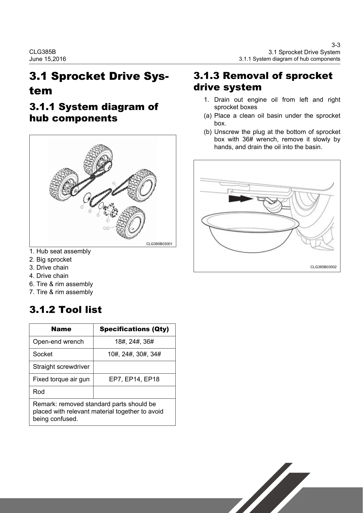
Liugong CLG385B Skid Steer Loader Service Manual - YANMAR 4TNV98CT Engine β€” PDF page 61 preview
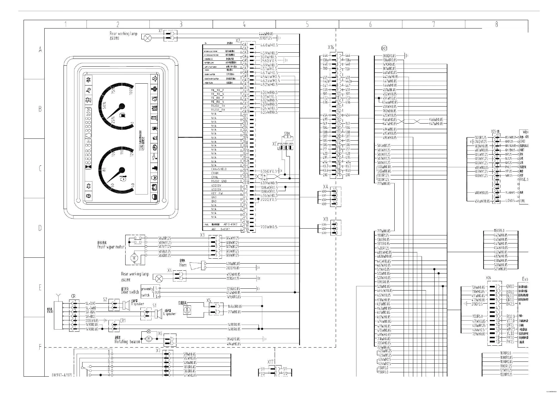
Liugong CLG385B Skid Steer Loader Service Manual - YANMAR 4TNV98CT Engine β€” PDF page 82 preview
Liugong CLG385B Skid Steer Loader Service Manual - YANMAR 4TNV98CT Engine β€” PDF page 225 preview

Instant PDF Delivery

This Liugong CLG385B Skid Steer Loader Service Manual is delivered as a PDF file available for immediate download after purchase. There is no shipping, no waiting for a physical book, and no restrictions on how many times you access it. You can view it on a laptop, tablet, or smartphone in the workshop, print the pages you need for a specific job, and keep the complete manual on hand for future reference. The PDF format makes it easy to search for specific procedures, torque values, or wiring information when you need it most.
Reviews

There are no reviews yet.

Be the first to review “Liugong CLG385B Skid Steer Loader Service Manual – YANMAR 4TNV98CT Engine”

What Our Customers Say

β˜…β˜…β˜…β˜…β˜… Live reviews from customers
Loading customer reviews...
0
    0
    Your Cart
    Your cart is emptyReturn to Shop
    πŸ›’
    Recently Purchased
    πŸ•’ verified order