
MAN L48/60CR 8L Marine Engine Operating Instructions Technical Documentation May 2019
Original price was: $42.95.$24.95Current price is: $24.95.
Plant-specific MAN Energy Solutions operating instructions and technical documentation for the L48/60CR Common Rail marine main engine (8L 48/60 CR, works nos. 1130934–1130937, plant 4305244). Covers fuels and fluids, starting and monitoring, emergency running, systems, ratings, and maintenance scheduling.
Description
MAN L48/60CR 8L Marine Engine Operating Instructions Technical Documentation – May 2019
This volume is the English operating-instruction set issued for four in-line L48/60CR Common Rail engines installed under plant number 4305244. The title block identifies engine type L48/60CR and works numbers 1130934, 1130935, 1130936 and 1130937. Document 6724 B1-01 EN is dated 2019-05-10 and is marked as a translation of the original instructions from MAN Energy Solutions. The book is written for watchkeepers and plant operators who must start, load, monitor, change fuels, and shut down these engines without guessing at limits.
File Details
- Manual type: Operating instructions and technical documentation
- Brand / model: MAN Energy Solutions L48/60CR (8L 48/60 CR)
- Works numbers: 1130934, 1130935, 1130936, 1130937
- Plant number: 4305244
- Document: 6724 B1-01 EN / volume 010.005
- Date: 2019-05-10
- Language: English (translation of the original instructions)
- Page count: 398
- File format: PDF
Plant Identity and Purpose of This Set
The performance chapter names the delivered configuration as 8L 48/60 CR with TCA66 turbochargers (works 7003265 / 266 / 267 / 268), constant-pressure charging, Bureau Veritas factory acceptance, marine main-engine duty and variable-pitch propeller drive. Continuous rating is given as 9600 kW at 500 rpm under ISO 3046/I reference air of 45 °C, intercooler water 38 °C, 1 bar and sea level. Works 1130934 and 1130935 rotate clockwise from the flywheel end; works 1130936 and 1130937 rotate counterclockwise. Fuel allowance on this plant is marine diesel oil and heavy fuel oil at 380 mm²/s, with remote control and unattended / central monitoring marked applicable.
The characteristic-features chapter describes the 48/60 CR family as turbocharged four-stroke engines of 480 mm bore and 600 mm stroke, built in in-line and V form, using Common Rail instead of a conventional jerk pump. Cylinder capacity is 108.5 dm³ and cylinder spacing is 820 mm. Average piston speed at the stated rating is 10.0 m/s. Heavy-fuel consumption at the reference condition is listed as 175.5 g/kWh plus 5 % tolerance at 8160 kW / 85 % and 30 mbar exhaust back pressure, without attached pumps. Lubricating-oil consumption is 0.5 g/kWh with a +20 % tolerance. NOx is referenced to IMO revised MARPOL Annex VI-2008, Reg. 13 (4) Tier II in liquid mode.
This book is the operating and systems volume for that plant. It does not replace the separate Engine Work Instructions volume 010.005, the spare-parts catalogue, the test-run report in volume 010.330, or the SaCoSone measuring-device list in volume 010.290. Those companion books are named in the structure chapter so the reader knows where step-by-step overhaul tasks live. Use this file for daily operation, fluid quality, load limits, fault response and the published maintenance intervals.
Engine Construction – What the Operator Is Expected to Know
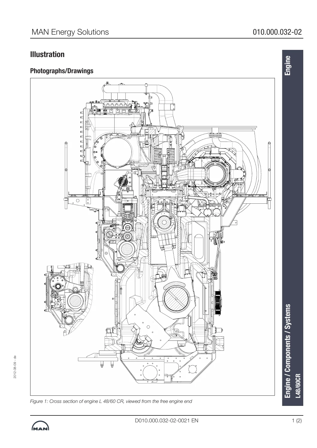
Looking onto the coupling, the exhaust pipe sits on the right (AS) and the charge-air pipe on the left (AGS). The camshaft lies in a trough on the exhaust-counter side and drives inlet and exhaust valves plus the high-pressure pumps. Variable Valve Timing (VVT) can shift inlet timing to improve part-load exhaust values. Common Rail sets injection timing and duration. On propeller plants the turbocharger and charge-air cooler normally sit on the coupling end; a free-end drive can run cooling-water and lube-oil pumps. Fuels up to 700 mm²/s at 50 °C through CIMAC H/K 55 are discussed for the series; this plant’s data sheet flags HFO 380 mm²/s and MDO.
Sub-assembly text walks through the two-part oil-cooled stepped piston, backing ring and top-land ring, cylinder liner cooling path, two inlet and two exhaust valves with rotators, centrally mounted cooled injection valves, series-connected Common Rail accumulator units, cam-driven high-pressure pumps with throttle-valve feed control, TCA-series turbochargers (radial compressor, axial turbine) and the leaf-spring torsional vibration damper on the free end. Component weights for an 8L 48/60 CR include a crankshaft with counterweights of 18,230 kg, crankcase of about 49,044 kg and a complete engine of about 135 t. Those figures matter when planning lifts and when reading the maintenance schedule’s personnel estimates.
Operating Media and Running Limits
Section 2.3 specifies gas oil / MGO, MDO, HFO, the viscosity-temperature diagram, SAE 40 lubricating oil for HFO and for MGO/MDO, engine coolant, intake (combustion) air, compressed air, anti-corrosion agents and how operating fluids are to be analysed. Temperature and pressure tables then give the working envelope the watch must hold: charge air before the cylinder 45–58 °C, exhaust after the cylinder max. 480 °C (±40 K cylinder spread), exhaust before the turbocharger max. 570 °C, engine cooling water after the engine 90 °C regulated / max. 95 °C, nozzle cooling water 55–60 °C, lube oil before engine and turbocharger 50–55 °C with alarm/stop at ≥60 °C. Starting air is min. approx. 15 bar, max. 30 bar; control air 8 bar, min. 5.5 bar. Fuel ahead of the high-pressure pumps is 11–12 bar (min. 3 bar in a blackout). Common Rail safety / pressure-limiting valve opening pressure is 1850 + 100 bar. Injection-valve opening-pressure ranges are given for new and used nozzles together with the 4.5-turn ±30° adjusting-screw limit.
Valve timing at full load opens the exhaust 54 °KW before BDC and closes it 57 °KW after TDC; the inlet opens 74 °KW before TDC and closes at BDC, giving 131 °KW overlap. Partial-load VVT timings differ for clockwise and counterclockwise engines. Firing order for the eight-cylinder plant is 1-4-7-6-8-5-2-3-1 clockwise and 1-3-2-5-8-6-7-4-1 counterclockwise. Under a misfiring / worst-cylinder-against-compression condition the output must be reduced to 60 % MCR, preferably at nominal speed.
Chapters Covered
- 1 Introduction — Preface; Operator’s responsibility; Structure of the operating manual; Contact details (MAN PrimeServ Augsburg)
- 2.1 Prerequisites — Transport and on-site measures; Assembly / installation; Starting up; SaCoSone power-up after a long supply interruption
- 2.2 Safety — General notes and operator obligations; Intended use; Risks and hazardous points on the engine; Warning notices and PPE; Noise emission up to 110 dB(A)
- 2.3 Operating media — MGO, MDO, HFO, VT diagram; SAE 40 lube oil (HFO and MGO/MDO); Coolant; Fluid analysis; Intake air; Compressed air; Anti-corrosion agents
- 2.4 Operative Management I — Starting preparations, start and stop; Changeover diesel oil ↔ heavy fuel; Permissible outputs and speeds; Engine run-in
- 2.5 Operative Management II — Monitoring and routine work; Low-load operation; Output and working-point calculation; Reduced-speed running; Special-condition equipment; Bypass charge air; Condensate in charge-air pipes; Load application; Exhaust-gas blow-off; Auxiliary charge air
- 2.6 Operative Management III — Fault detection; Emergency running with a failed cylinder or turbocharger; Blackout; Failed cylinder lubrication or speed control; Alarms on exceeded values; Injection-valve cooling failure; Emergency stop; Automatic-filter failure
- 2.7 Operative Management IV — Shutting down and preserving; Decommissioning; Dismantling and disposal
- 3.1–3.3 Scope of supply, characteristic features, engine illustrations, sub-assemblies, special versions and additional equipment
- 3.4 Systems — Fresh air / charge air / exhaust; Compressed air and starting (including slow-turn and emergency flush of the rail); Fuel / Common Rail; Speed and power control; Lube oil; Cooling water; VVT; Leakage detection
- 3.5 Technical data — Performance and consumption; Temperatures and pressures; Weights; Dimensions, clearances and tolerances
- 4 Maintenance — Schedule explanation, special tools, spare parts, component replacement, services / repair, schedule symbols, systems schedule, engine schedule
- 5 Appendix — Designations and terms; Formulae; SI units; Symbols and abbreviations
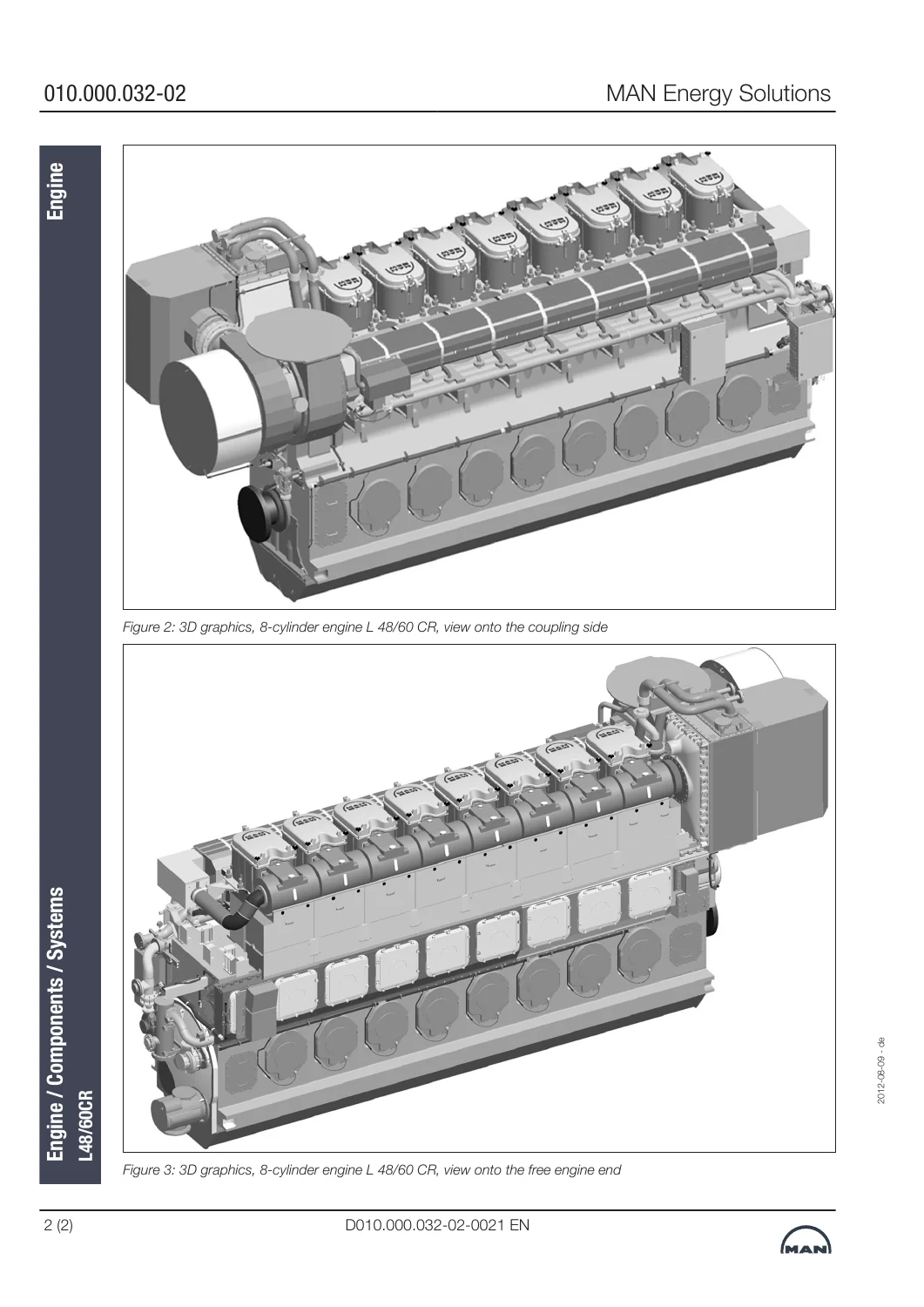
Taken together, the chapters give the operator the plant identity, the fluids and pressures that keep the Common Rail and TCA66 healthy, the start–load–stop sequence including SaCoSone self-test, the emergency paths when a cylinder, turbocharger, filter or power supply fails, and the interval framework that points into the separate work-instruction volume. Cross-section and 8-cylinder views, fuel-system schematics, high-pressure pump sections and hazardous-point drawings sit inside the same file so a new watch can see what the text is talking about.
Safety, Control and Daily Watchkeeping
Safety chapters define intended use (approved operating parameters, approved fluids, approved spare parts, original or manufacturer-approved configuration, current maintenance, authorised personnel only). Residual hazards are mapped on two engine drawings: flywheel and turning gear, crankcase covers and relief-valve danger zones (4 m × 0.5 m), Common Rail jacketing, exhaust covers, hydraulic tensioners and live electrical cabinets. Crankcase covers must stay closed for 20 minutes after shutdown. Average A-weighted emission sound pressure is given up to 110 dB(A); hearing protection with at least 25 dB(A) attenuation is required above 85 dB(A).
Starting-air text covers the main starting valve, starting-air pilot valves and starting cams, flame arrestors at the liner backing rings, drain and decompression cocks, the M 329/2 emergency-stop combination that flushes the Common Rail, and the slow-turn device that rotates the engine about three revolutions at roughly 8 bar before an automatic start. After a long SaCoSone power loss the UPS batteries must be allowed to recharge before an engine start; the system self-tests on power-up and every new alarm must be acknowledged and cleared.
What the MAN L48/60CR 8L Marine Engine Operating Instructions Technical Documentation May 2019 Lets You Do
With this file on the watch station you can identify the four works numbers and the 9600 kW / 500 rpm rating, choose and analyse MGO, MDO and 380 mm²/s HFO against the printed specifications, preheat water and oil to the stated minima, start and stop through the compressed-air and Common Rail path, change between distillate and residual fuel, hold low-load and reduced-speed rules, calculate working-point status, and follow the written response when a cylinder, turbocharger, automatic filter, injection-valve cooling circuit or ship’s power supply fails. You also have the published temperatures, pressures, valve timings, firing orders, component weights, bearing clearances and maintenance-schedule structure that keep an 8L 48/60 CR inside its design envelope. Correct figures matter on a 135-tonne, 1850-bar rail engine: a wrong injection viscosity, a skipped slow-turn, or running through a misfire above 60 % MCR is how liners, rails and TCA66 bearings are lost.
Delivery is an instant PDF download after payment. There is no printed-book shipment and no waiting on a parts desk. Open the file on a ship’s PC, tablet or phone and print the pages you need for a watch handover or a planned stop. Use it beside the engine, not as a substitute for the separate work-instruction and spare-parts volumes named in the text.
Reviews
There are no reviews yet.