
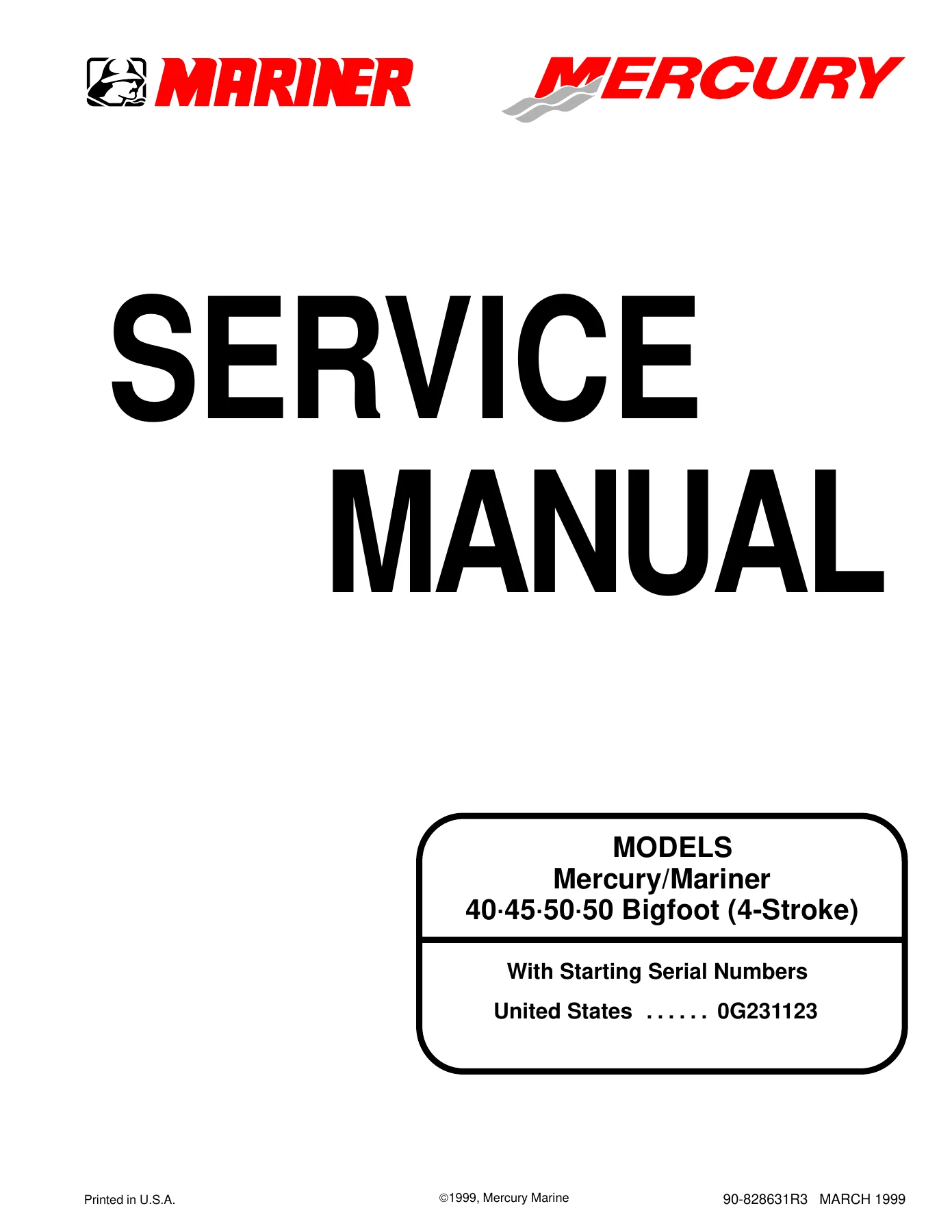
Mercury Mariner 40 45 50 HP 4-Stroke Outboard Service Manual 1999 – 50 Bigfoot Repair PDF
Original price was: $39.95.$23.95Current price is: $23.95.
Complete Mercury Marine service manual for the Mercury/Mariner 40, 45, 50 and 50 Bigfoot four-stroke outboards. 599 pages covering the 935 cc overhead-cam powerhead, CDI ignition, charging and starting, carburetors, power trim, mid-section and both gear housing designs. Publication 90-828631R3, March 1999, US models from serial 0G231123.
Description
Mercury/Mariner 40-50 HP 4-Stroke Outboard Service Manual (90-828631R3)
This is the complete Mercury Marine service manual for the Mercury/Mariner 40, 45, 50 and 50 Bigfoot four-stroke outboard engines, published under part number 90-828631R3 in March 1999 and covering United States models from serial number 0G231123 upward. It is the same bench reference used for teardown, inspection, measurement, reassembly and adjustment of the 935 cc overhead-cam four-cylinder powerhead and everything bolted to it – from the capacitor discharge ignition and charging system through the four-carburetor bank, power trim hydraulics, mid-section and both gear housing designs.
File Details
- Manual type: Service manual (workshop / repair)
- Brand: Mercury Marine – Mercury and Mariner
- Models: 40, 45, 50 and 50 Bigfoot (4-Stroke)
- Engine: 935 cc (57 cu. in.), 4-cylinder, 4-stroke, overhead camshaft
- Language: English
- Page count: 599 pages
- File format: PDF
- Publication number: 90-828631R3
- Edition / date: March 1999
- Starting serial number: 0G231123 (United States)
Chapters Covered in This Mercury/Mariner 4-Stroke Outboard Manual
- Section 1 – Important Information: Specifications; Maintenance; General Information; Outboard Motor Installation
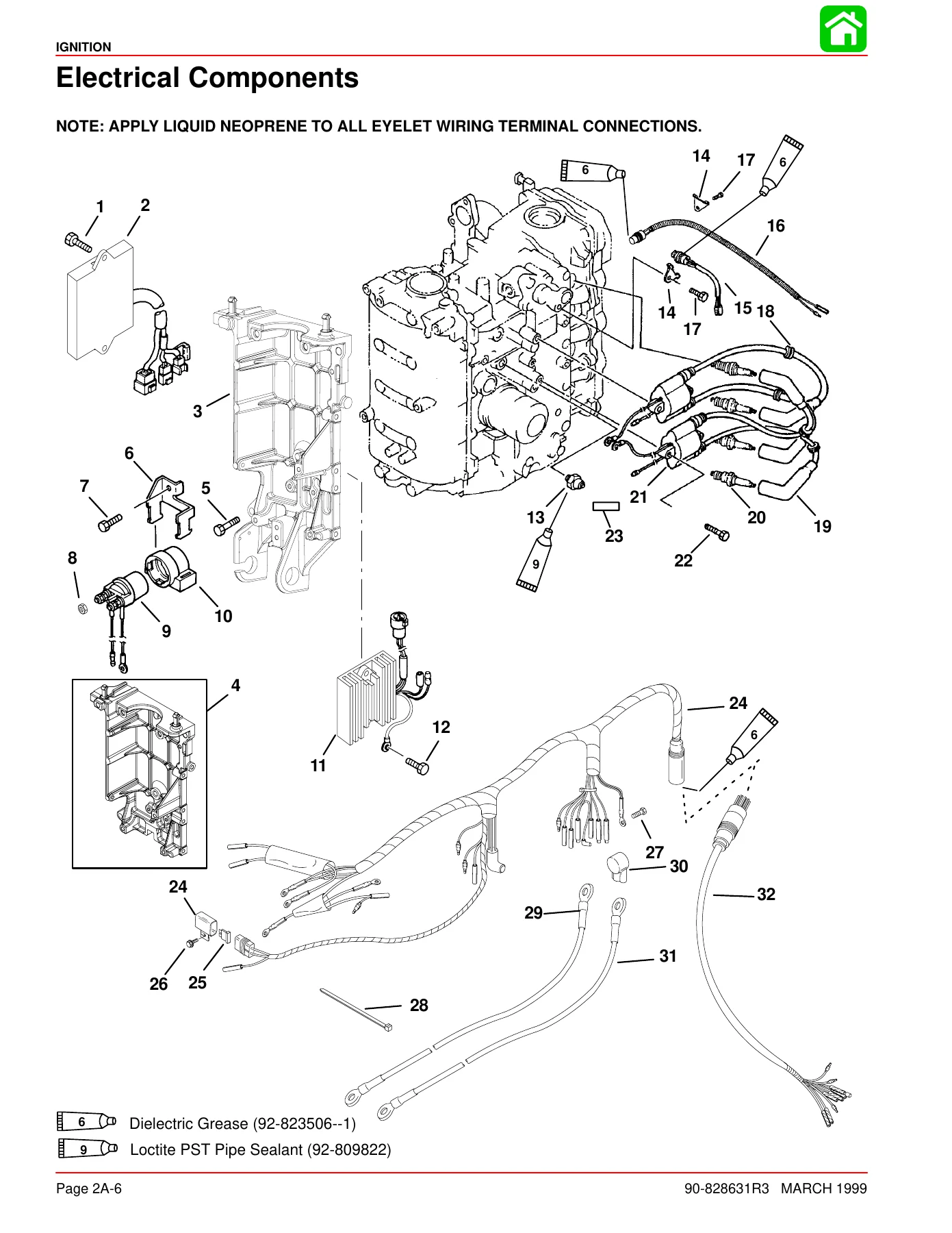
- Section 2 – Electrical: Ignition; Charging & Starting System; Timing, Synchronizing & Adjusting; Wiring Diagrams
- Section 3 – Fuel System: Fuel Pump; Carburetor; Emissions
- Section 4 – Powerhead: Cylinder Head; Cylinder Block/Crankcase; Lubrication
- Section 5 – Mid-Section: Clamp/Swivel Brackets & Drive Shaft Housing; Power Trim (1998 and Earlier Non-Bigfoot); Power Trim (1999 and Later Non-Bigfoot / All Bigfoot Model Years); Manual Tilt Assist
- Section 6 – Gear Housing: Non-Bigfoot Gear Housing; Bigfoot Gear Housing
- Section 7 – Attachments/Control Linkage: Throttle/Shift Linkage; Tiller Handle
Everything is organised so a job can be found quickly and worked through in the right order. Each section opens with its own specification table and special-tool list, then walks through removal, disassembly, cleaning and inspection, measurement against service limits, reassembly and final adjustment. Torque figures, clearances and wear limits are given inline with the step that needs them, and the exploded illustrations show how components stack together before you take them apart. The electrical material includes full wiring diagrams for the electric-start remote models, tiller handle models, Commander remote controls and the power trim switch circuit, so diagnosing a no-spark or no-charge fault is a matter of following the diagram rather than guessing.
Engine Specifications, Torque Values and Service Limits
The specification chapter lists horsepower and rated rpm for each model, outboard weights, fuel and oil requirements, engine oil capacity, compression ratio, cylinder compression, cylinder bore and taper limits, piston and ring dimensions, ring end gap and side clearance, piston pin and connecting rod clearances, crankshaft main bearing clearance and run-out, camshaft lobe and journal dimensions, valve spring free length and tilt, valve clearance, valve seat width and margin thickness, valve guide bore and stem-to-guide clearance, and cylinder head warpage limits. Ignition data covers spark plug type and gap, firing order, fully retarded and fully advanced timing windows, charge coil, trigger coil and ignition coil resistance values, CDI engine speed limiter range and overheat speed control range. Charging and starting data covers alternator type and regulated output, lighting coil resistance and peak voltage, starter type and output, load and no-load ampere draw, and minimum battery ratings including the cold-weather recommendation.
Electrical, Ignition and Charging Diagnosis
The ignition section explains how the capacitor discharge system produces and stores voltage, how the trigger coil fires the SCR gate, and how the stop circuit kills spark. It provides DVA test positions and expected voltage readings for the coil primary, stator charge coil and CDI stop circuit, plus ohm checks for the trigger coil, stator, lighting coil, ignition coil primary and secondary, spark plug cap resistor and thermo switch. Troubleshooting tables map symptoms such as no spark on both cylinders, no spark on one cylinder, weak spark, timing that will not advance, misfire at high rpm, hard cold starting, hard hot starting and an engine that will not run over 2000 rpm to the probable cause and the test to perform. Flywheel removal and installation, stator, trigger coil, CDI unit, ignition coil and rectifier removal and installation are all covered with torque figures.
Fuel System and Carburetor Work
The fuel system section covers the external plunger/diaphragm fuel pump – operation, removal, disassembly, cleaning and inspection, reassembly and installation – along with the fuel filter, check valves and springs. The carburetor section deals with the four-carburetor bank as a unit and individually: linkage layout, choke rod and auto-choke links, carburetor removal and installation, float bowl, float, float pin, needle valve, main nozzle, main jet, pilot jet and idle mixture screw service, plus float height measurement. Adjustment procedures include static carburetor synchronisation, idle mixture screw setting, choke cam angle adjustment against the thermal gap graph, fast idle adjustment, unloader adjustment and choke shutter closing adjustment, with separate procedures for 40/45 hp and 50 hp jetting. Dynamic synchronisation using a carburetor tuner and intake manifold vacuum readings is described step by step, as is CO checking through the exhaust manifold adaptor.
Powerhead, Cylinder Head and Valve Service
The powerhead material covers cylinder head removal and disassembly, rocker arm shaft and rocker arm inspection, camshaft removal and installation, valve removal and installation using a spring compressor, valve guide replacement with the guide remover, installer bushing and reamer, valve seat reconditioning with cutter angles, valve refacing steps and margin thickness checks, camshaft oil seal installation, oil pump assembly and installation, and cylinder head gasket and head bolt torque sequences. Timing belt inspection, removal and installation are given in full, including alignment marks on the drive and driven gears and tensioner torque. Valve clearance adjustment is laid out in two stages – No. 1 and No. 2 intake with No. 1 and No. 3 exhaust, then No. 3 and No. 4 intake with No. 2 and No. 4 exhaust – with the cold clearance specification and adjusting nut torque.
Cylinder Block, Crankshaft and Lubrication
The cylinder block section takes the engine down to the crankshaft: powerhead removal and installation, cylinder block disassembly, piston and connecting rod removal, cylinder bore measurement at three positions on two axes, piston measurement, piston pin and ring checks, ring side clearance and end gap, crankshaft run-out, main bearing clearance and connecting rod bearing clearance checked with plastigauge, main bearing and connecting rod bearing colour-code selection, piston ring installation with end gap positioning, piston installation with the UP mark toward the flywheel, crankshaft installation, crankcase cover sealing with gasket sealant and the two-stage bolt torque sequence, exhaust cover and thermostat cover installation, and drive gear installation with the correct nut torque. The lubrication chapter covers the trochoid oil pump – disassembly, rotor and housing clearance measurement, reassembly and installation with O-ring seals and priming.
Mid-Section, Power Trim and Manual Tilt
Mid-section coverage includes the transom brackets, swivel bracket, drive shaft housing, adaptor plate, steering arm and bottom cowl, with grease points and torque values. Two separate power trim chapters are included because the system changed: one for 1998 and earlier non-Bigfoot models and one for 1999 and later non-Bigfoot plus all Bigfoot model years. Both give the theory of operation with flow diagrams for trim up, tilt up, maximum tilt, trim down, shock function up, shock function return and manual tilt, then the hydraulic troubleshooting flow charts for an outboard that will not hold a tilted position and a trim system that leaks down, the electrical troubleshooting table for the trim and cowl switches and relays, complete disassembly and reassembly with O-ring sizes and placement, trim motor tests, bleeding procedure and installation. The manual tilt assist chapter follows the same pattern with its own flow diagrams, accumulator handling, valve block service and fluid filling procedures.
Gear Housing – Non-Bigfoot and Bigfoot
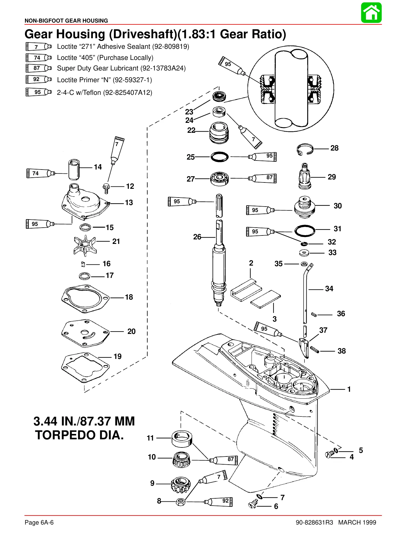
Both gear housing designs are covered in their own chapters with their own specifications. The non-Bigfoot 1.83:1 housing and the Bigfoot 2.31:1 housing each get draining and inspection of gear lubricant, removal, water pump disassembly and reassembly, bearing carrier and propeller shaft service, pinion gear, drive shaft and forward gear work, shift shaft service, bearing and seal replacement with the correct drivers and mandrels, and gear housing pressure testing. The Bigfoot chapter adds pinion gear depth measurement using the pinion gear locating tool, gauging block and shims, and forward gear backlash measurement with the dial indicator and backlash indicator tool. Trim tab adjustment, gear housing installation, shift operation checks and filling with lubricant are covered for both.
Maintenance Schedules, Storage and General Information
The maintenance chapter gives the before-each-use and after-each-use checks, the 100-hour or annual service list, the 300-hour or three-year item, and storage preparation for fuel system, external components, internal engine components, gear case, positioning and battery. Corrosion control anode locations and replacement, spark plug inspection and gap setting, battery inspection, fuse replacement, timing belt inspection, lubrication points, power trim fluid checking, engine oil and filter changing, and gear case lubrication are all included with illustrated procedures. General information covers serial number location, conditions affecting performance, propeller selection and charts for both gear ratios, propeller removal and installation for Flo-Torque I and II hubs, compression checking, cylinder leakage testing, painting procedures and decal application.
Who This Mercury/Mariner 4-Stroke Outboard Service Manual Is For
This is written for anyone doing real work on a 40, 45, 50 or 50 Bigfoot four-stroke Mercury or Mariner outboard – routine maintenance, seasonal service, ignition and charging faults, fuel and carburetor problems, powerhead repair, power trim or manual tilt service, and complete gear housing rebuilds. Because the manual separates the 1998-and-earlier power trim from the 1999-and-later system, and covers both the 1.83:1 non-Bigfoot and the 2.31:1 Bigfoot gear housing, you can work on either configuration without needing a second book. Serial number ranges are called out wherever a running change affects the procedure, so you can confirm the step applies to your engine before you start.
IMAGES PREVIEW
Instant PDF Delivery
You get the full 599-page Mercury/Mariner 40-45-50-50 Bigfoot four-stroke outboard service manual as a PDF the moment payment clears – no shipping, no waiting, no postage. Keep it on a laptop or tablet in the workshop, print the pages for the job in front of you, or print the whole thing for the bench. Having the correct torque figures, clearances, timing windows, bearing colour codes and adjustment procedures on hand is what separates a repair that lasts from one that comes back – and this manual gives you all of it, straight from the manufacturer’s own service publication.

Reviews
There are no reviews yet.