Description
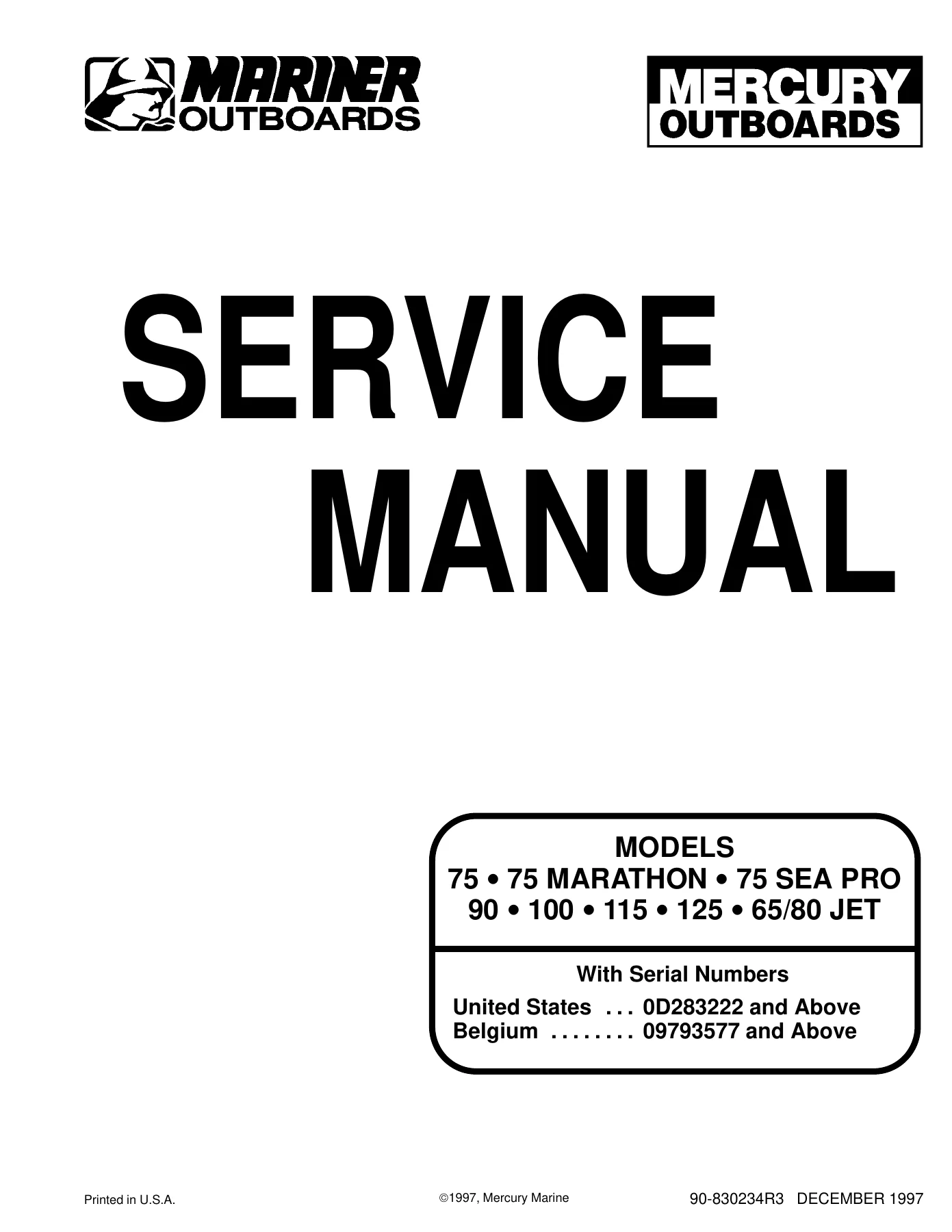
The Mercury Mariner 65-125 HP Outboard Service Manual is a comprehensive workshop manual covering 3-cylinder and 4-cylinder 2-cycle outboard engines. This manual spans the full range of models from 65 HP Jet through 125 HP, including the 75, 75 Marathon, 75 Sea Pro, 90, 100, 115, and 125 HP engines, as well as the 65 Jet and 80 Jet drive versions. Published by Mercury Marine in December 1997 under document number 90-830234R3, this service manual provides the detailed procedures, specifications, and diagrams needed for professional repair and maintenance of these outboard motors.
File Details
- Manual Type: Service Manual
- Brand: Mercury Marine / Mariner
- Models Covered: 75, 75 Marathon, 75 Sea Pro, 90, 100, 115, 125, 65 Jet, 80 Jet
- Engine Type: 3-cylinder and 4-cylinder, 2-cycle outboard
- Language: English
- Page Count: Approximately 585 pages
- File Format: PDF
- Document Number: 90-830234R3
- Date: December 1997
- Serial Number Coverage: United States 0D283222 and Above; Belgium 09793577 and Above
Chapters Covered
- Section 1 – Important Information: Specifications, Maintenance, General Information, Outboard Installation
- Section 2 – Electrical: Ignition, Charging & Starting System, Timing/Synchronizing/Adjusting, Wiring Diagrams
- Section 3 – Fuel System: Fuel Pump, Carburetor, Oil Injection, Emissions
- Section 4 – Powerhead: Complete powerhead service and overhaul procedures
- Section 5 – Mid-Section: Clamp/Swivel Brackets & Drive Shaft Housing, Power Trim, Shock Absorber, Manual Tilt
- Section 6 – Lower Unit: Lower Unit, Jet Drive
- Section 7 – Attachments/Control Linkage: Throttle/Shift Linkage, Tiller Handle
- Section 8 – Manual Starter: Manual starter assembly and rewind procedures
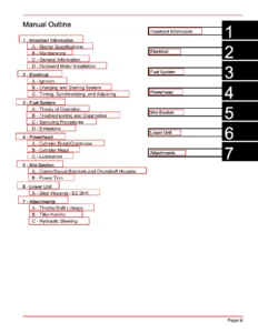
This Mercury Mariner outboard service manual is organized into eight major sections, each covering a critical system or assembly of the engine. The manual begins with essential specifications and maintenance schedules, then progresses through electrical systems, fuel delivery, powerhead internals, mid-section components, lower unit and jet drive, control linkages, and manual starter systems. Each section includes detailed procedures, exploded-view illustrations, wiring diagrams, and specification charts to guide the technician through every repair and maintenance task.
Model Coverage & Applications
The Mercury Mariner 65-125 HP Outboard Service Manual covers a wide range of 3-cylinder and 4-cylinder 2-cycle outboard engines produced for the United States and Belgian markets. The manual applies to the following models:
- 3-Cylinder Models: 75, 75 Marathon, 75 Sea Pro, 90, 65 Jet
- 4-Cylinder Models: 100, 115, 125, 80 Jet
Serial number coverage begins at 0D283222 for United States models and 09793577 for Belgium models, with the manual supporting all subsequent serial numbers produced during the covered period. Whether you are working on a 75 HP work model or a 125 HP performance outboard, this manual provides the factory specifications and procedures needed to complete the job correctly.
Systems & Procedures Covered
This Mercury Mariner service manual covers every major system on the outboard, from ignition and charging to fuel delivery, powerhead internals, and lower unit service. The electrical section includes complete ignition system diagnostics, charging and starting system troubleshooting, timing and synchronization procedures, and full wiring diagrams for all covered models. The fuel system section details fuel pump service, carburetor overhaul and adjustment, oil injection system setup and testing, and emissions information.
Powerhead coverage includes complete disassembly, inspection, and reassembly procedures for both 3-cylinder and 4-cylinder engines, including crankshaft, piston, connecting rod, and cylinder block service. The mid-section section covers clamp and swivel bracket service, power trim systems for both early and late serial number ranges, shock absorber service, and manual tilt systems. Lower unit coverage includes gear housing service, water pump replacement, propeller shaft and gear set procedures, and jet drive service for 65 Jet and 80 Jet models.
Control linkage coverage includes throttle and shift cable installation and adjustment, tiller handle service, and remote control installation. The manual starter section provides complete rewind starter disassembly, inspection, and reassembly procedures. Throughout the manual, torque specifications, service limits, and adjustment values are provided to ensure every repair is completed to factory standards.
Why This Manual Matters
Having the correct service information is essential when working on any outboard motor. The Mercury Mariner 65-125 HP Outboard Service Manual provides the exact procedures, specifications, and diagrams that Mercury Marine used when these engines were in production. This eliminates guesswork and ensures that every repair, adjustment, and maintenance task is done correctly the first time.
Whether you are a professional marine mechanic or a boat owner performing your own maintenance, this manual gives you access to the same information that authorized dealers use. From simple tasks like spark plug replacement and gear case lubrication to complex jobs like powerhead overhaul and lower unit gear set installation, the manual walks you through each procedure with detailed instructions and illustrations.
Complete PDF Bookmark Tree
Complete Bookmarks
The complete bookmarks in the βMercury Mariner 65-125 HP Outboard Service Manual – 75 90 100 115 125 & 65/80 Jet Repairβ are as follows:
+cover.pdfp. 1
+MODELS 75 75 MARATHON 75 SEA PRO 90 100 115 125 65/ 80 JETp. 1
Noticep. 2
Notice to Users of This Manualp. 2
Cleanliness and Care of Outboard Motorp. 2
How To Use This Manualp. 3
Page Numberingp. 3
Propeller Informationp. 3
Service Manual Outlinep. 4
+1ap. 5
+SPECIFICATIONSp. 5
Table of Contentsp. 6
Master Specificationsp. 7
+1bp. 13
+MAINTENANCEp. 13
Table of Contentsp. 14
Specificationsp. 15
Special Toolsp. 15
Quicksilver Lubricant/Sealantp. 15
+Inspection And Maintenance Schedulep. 16
Before Each Usep. 16
After Each Usep. 16
Every 100 Hours of Use or Once Yearly, Whichever Occurs Firstp. 16
Every 300 Hours of Use or Three Yearsp. 16
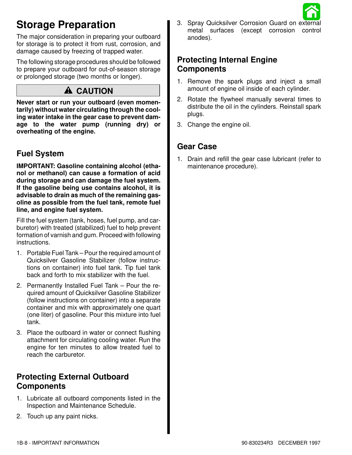
Before Periods of Storagep. 16
Flushing The Cooling Systemp. 17
+Fuel Systemp. 17
Fuel Line Filterp. 17
Fuel line Filter β Non-Oil Injected Modelsp. 18
Fuel Line Inspectionp. 18
Corrosion Control Anodep. 18
Spark Plug Inspectionp. 19
Battery Inspectionp. 19
Fuse Replacement β Electric Start Modelsp. 19
Lubrication Pointsp. 19
Checking Power Trim Fluidp. 21
+Gear Case Lubricationp. 21
Checking Lubricant Level and Filling Gear Casep. 21
+Storage Preparationp. 22
Protecting External Outboard Componentsp. 22
Protecting Internal Engine Componentsp. 22
Gear Casep. 22
Fuel Systemp. 22
Positioning Outboard for Storagep. 23
Battery Storagep. 23
+1cp. 24
+GENERAL INFORMATIONp. 24
Table of Contentsp. 25
Serial Number Locationp. 26
+Conditions Affecting Performancep. 26
Weatherp. 26
Boatp. 27
Enginep. 27
+Following Complete Submersionp. 28
Submerged While Running (Special Instructions)p. 28
Salt Water Submersion (Special Instructions)p. 28
Fresh Water Submersion (Special Instructions)p. 28
Propeller Selectionp. 29
Propeller Installationp. 29
+Power Trim Systemp. 30
General Informationp. 30
Power Trim Operationp. 30
Trim "In" Angle Adjustmentp. 31
Compression Checkp. 31
Painting Proceduresp. 32
Decal Applicationp. 33
+1dp. 34
+OUTBOARD INSTALLATIONp. 34
Table of Contentsp. 35
Notice to Installer and Ownerp. 36
Boat Horsepower Capacityp. 36
Outboard Remote Controlp. 36
Selecting Accessories For The Outboardp. 36
Selecting Steering Cables and Remote Control Cablesp. 36
Determining Recommended Outboard Mounting Heightp. 37
+Locating Center Line Of The Outboardp. 38
Drilling Outboard Mounting Holesp. 38
Lifting Outboardp. 39
Installing Outboard to Boat Transomp. 39
+Single Steering Cable and Steering Link Rod Installationp. 40
Installing Ride Guide Steering Cable To The Outboardp. 40
Steering Link Rod Installationp. 40
Co-Pilot Installation (Tiller Handle models)p. 41
Remote Control Installationp. 42
+Required Side Mount Remote Control or Ignition Key Switch Assemblyp. 42
Boats Equipped with Side Mount Remote Controlp. 42
Boats Equipped with Panel Or Console Mount Remote Controlp. 42
Connecting Remote Wiring Harness To The Enginep. 44
+Shift and Throttle Cable Installation to the Outboardp. 42
Shift Cable Installationp. 42
Throttle Cable Installationp. 43
Battery Connectionsp. 45
+Set Up Instructions For Oil Injection Systemp. 45
Filling The Oil Injection Systemp. 46
Bleeding Air From the Oil Injection Systemp. 46
Adjusting The Oil Injection Pumpp. 47
Trim Tab Adjustmentp. 47
+2ap. 48
+IGNITIONp. 48
Table of Contentsp. 49
Special Toolsp. 50
3 Cylinder Electrical Components (USA-0G127499/BEL-9836632 & BELOW)p. 51
Electrical Components (USA-0G127500 thru 0G437999)(BEL-9836633 thru 9926999)p. 53
3 Cylinder Electrical Components (USA-S/N-0G438000/BEL-9937000 & UP)p. 55
4 Cylinder Electrical Components (S/N-USA-437999/BEL-9926999 & BELOW)p. 57
4 Cylinder Electrical Components (USA-S/N-0G438000/BEL-9937000 & UP)p. 59
Descriptionp. 61
+Test Proceduresp. 61
Direct Voltage Adapter (DVA) Testsp. 61
Test Sequencep. 62
+Ignition System DVA Specifications Test Chartp. 63
3 Cylinder Stators 75 Manual with 9 Ampere Stator 398-9873A20, USA-0D283222 thru 0G227199 75/90 Electric with 16 Ampere Stator 398-9710A3, USA-0D283222 thru 0G280043 Belgium-09793577 thru 09879064p. 63
4 Cylinder with 16 Ampere Stator 398-9710A31 USA-0D283222 thru 0G301750 Belgium-09793577 thru 09885527p. 63
3 Cylinder Stators 75 Manual with 9 Ampere Stator 398-9873A21, USA-0D227200 and Above 75/90 Electric with 14 Ampere Stator 398-9873A24, USA-0G280044 thru 0G404505 Belgium-09879065 thru 09916672p. 64
4 Cylinder with 16 Ampere Stator 398-9710A33 USA-0G301751 and Above Belgium – 09885528 thru 09916721p. 64
ADI Ignition using a RED Stator with an Adapter Modulep. 66
+RED Stator with Adaptor and Ignition Coilsp. 67
RED Stator DVA Testp. 67
Electric Start Enginesp. 67
Manual Start Enginesp. 67
Troubleshooting Proceduresp. 67
+Theory of Operationp. 68
Capacitor Charging #1 CDMp. 69
Capacitor Charging #2 & #3 CDMp. 70
#1 Cylinder Trigger Circuitp. 71
Ignition Coil Circuitp. 72
Stop Circuitp. 73
Rev Limiter Circuitp. 74
+RED Stator with CDMp. 75
Ignition Component Descriptionp. 75
CDM (P/N 827509)p. 76
Spark Gap Tester P/N 91-850439p. 76
CDM Test Harness 84-825207A2p. 76
Direct Voltage Adaptor (DVA) Testp. 81
Resistance Testsp. 83
Ignition (Key) Switch Testp. 84
Flywheel Removal and Installationp. 84
Stator Removal and Installationp. 85
Trigger Removal and Installationp. 88
Ignition Coil Removal and Installationp. 90
Switch Box Removal and Installationp. 91
+2bp. 92
+CHARGING AND STARTING SYSTEMp. 92
Table of Contentsp. 93
Specificationsp. 94
Special Toolsp. 95
+Batteryp. 95
Precautionsp. 95
Operating Engine Without Batteryp. 95
Specific Gravity Readingsp. 95
Electrolyte Levelp. 96
Charging a Discharged Batteryp. 96
Winter Storage of Batteriesp. 97
BLACK Stator Battery Charging System Troubleshootingp. 97
9 Ampere (Manual Start) BLACK Stator Output Testp. 98
BLACK Stator Ohms Test (Alternator Coils Only)p. 98
BLACK Stator 14 and 16 Amphere Alternator System Testp. 98
Tachometer Terminal Blockp. 99
RED Stator Battery Charging System Troubleshootingp. 99
3 Cylinder 14 and 16 Ampere BLACK Stator Battery Charging Wiring Diagramp. 102
4 Cylinder 14 and 16 Ampere BLACK Stator Battery Charging Wiring Diagramp. 103
3 Cylinder Battery Charging Diagram (with BLACK STATOR) with Battery Isolatorp. 104
3 Cylinder Battery Charging Diagram (with RED STATOR) with Battery Isolatorp. 105
4 Cylinder Battery Charging Diagram (with BLACK Stator) with Battery Isolatorp. 106
4 Cylinder Battery Charging Diagram (with RED Stator) with Battery Isolatorp. 107
Rectifier Testp. 108
+Starting Systemp. 109
Starting System Componentsp. 109
Descriptionp. 109
Troubleshooting the Starting Circuitp. 109
Starting Circuit Troubleshooting Flow Chartp. 110
+Starter Motorp. 112
Removalp. 112
Disassemblyp. 112
Starter Cleaning, Inspection and Testingp. 113
Testingp. 113
Brush Replacementp. 115
+2cp. 119
+TIMING/SYNCHRONIZING/ADJUSTINGp. 119
Table of Contentsp. 120
+Timing/Synchronizing/Adjusting (3 Cylinder Models)p. 121
Specificationsp. 121
Special Toolsp. 121
Throttle Cable Installationp. 125
+Timing/Synchronizing/Adjusting (4 Cylinder Models)p. 125
Specificationsp. 125
Special Toolsp. 125
Idle Adjustmentp. 129
Throttle Cable Installationp. 129
+2dp. 130
+WIRING DIAGRAMSp. 130
Table of Contentsp. 131
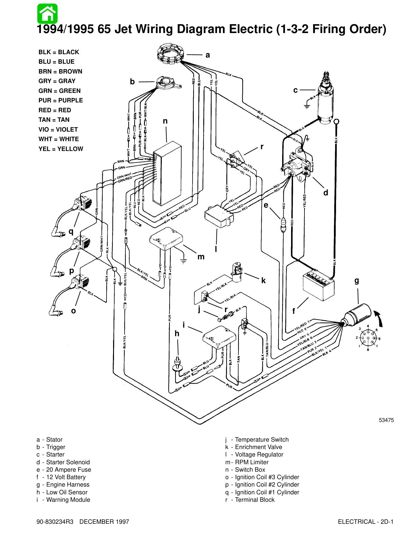
1994/1995 65 Jet Wiring Diagram Electric (1-3-2 Firing Order)p. 132
1996 65 Jet Wiring Diagram Electric (1-2-3 Firing Order)p. 133
1994/1995 75/90 Wiring Diagram (1-3-2 Firing Order)p. 134
1996 75/90 Wiring Diagram (1-2-3 Firing Order)p. 135
1994/1995 75 Work Model Wiring Diagram Manual Start (1-3-2 Firing Order)p. 136
1996 75 Work Model Wiring Diagram Manual Start (1-2-3 Firing Order)p. 137
1994/1995/1996 80 Jet/100/115/125 Wiring Diagramp. 138
1997 65 Jet Wiring Diagram (w/CDM) (1-2-3 Firing Order)p. 139
1997 75 Work Model Wiring Diagram (w/CDM) Manual Start (1-2-3 Firing Order)p. 140
1997 75/90 Wiring Diagram (w/CDM) (1-2-3 Firing Order)p. 141
1997 80 Jet/100/115/125 Wiring Diagram (w/CDM)p. 142
1998 65 Jet Wiring Diagramp. 143
1998 75 Work Model Wiring Diagramp. 144
1998 75 Electric Start Tiller Handle w/Power Trim Wiring Diagramp. 145
1998 75/90 Electric Start Wiring Diagramp. 146
1998 75/90 Electric Start w/Power Trim Wiring Diagramp. 147
+1998 80 Jet/100/115/125 Wiring Diagramp. 148
Power Trim System Wiring Diagram (3 Cylinder Models Using COMMANDER 2000 Side Mount Remote Control)p. 149
Power Trim System Wiring Diagram (3 Cylinder Models Using COMMANDER Side Mount Remote Control)p. 150
Power Trim System Wiring Diagram (4 Cylinder Models Using COMMANDER 2000 Side Mount Remote Control)p. 151
Tachometer (With Adjustable Dial) and Trim Indicator Gauge Wiring Diagramp. 152
Key/Choke Switch Continuity Test (COMMANDER 2000 Side Mount Remote Control)p. 153
COMMANDER 2000 Side Mount Remote Control (Power Trim/Tilt Electric Start with Warning Horn) Wiring Diagramp. 154
COMMANDER 2000 Side Mount Remote Control (Electric Start with Warning Horn) Wiring Diagramp. 155
COMMANDER 2000 Side Mount Remote Control (Power Trim/Tilt Electric Start with Warning Horn) Wiring Diagramp. 156
+3ap. 157
+FUEL PUMPp. 157
Table of Contentsp. 158
65 Jet 75-90 (3 cyl.)p. 160
80 Jet-100-115-125 (4 cyl.)p. 161
Fuel Pump (65 Jet/75/90)p. 162
Fuel Pump (80 Jet/100/115/125)p. 166
+Theory Of Operationp. 168
Troubleshooting Fuel Pumpp. 168
Removalp. 169
+Fuel Pump β Cleaning/Inspectionp. 169
Check Valve Reassemblyp. 169
Reassemblyp. 170
Installation of Fuel Pumpp. 171
+3bp. 172
+CARBURETORp. 172
Table of Contentsp. 173
Specificationsp. 174
WME Carburetor Chartp. 174
Special Toolsp. 176
Carburetor (WMEβ29/30/31/41/46/47/48/49)p. 177
Carburetor (WMEβ59/60/61/62/75/76/77/78/82/83)p. 179
CarburetorβWME-32/32A/33/34/40/40Ap. 183
+CarburetorβWME-50/51/52/79/80/81p. 185
Fuel System (Linkage)p. 189
+Adjustmentsp. 190
Idle Mixture Screw Adjustmentp. 190
Idle Speed Adjustmentp. 190
Float Adjustmentp. 190
Main (High Speed) Jet Adjustmentp. 191
Jet Orifice Size Chartp. 191
High Altitude Jet Chartp. 192
+Fuel System Troubleshootingp. 193
General Informationp. 193
Problem: Engine Floodsp. 193
Problem: Engine Runs Too Richp. 193
Problem: Fuel Blow Back Out Of Carburetorp. 193
Problem: Rough Idlep. 193
Problem: Engine Turns Over But Will Not Start Or Starts Hard When Coldp. 194
Problem: Unable to Reduce Engine RPM to Slow Idlep. 194
Problem: Engine Runs Too Leanp. 195
Problems: -Engine Idles Rough And Stalls -Engine Runs Uneven Or Surges -Engine Will Not Acceleratep. 195
Inspectionp. 196
+Enrichener Systemp. 197
Description for Three Cylinder Enginesp. 197
Enrichener Valve Hose Installation – Three Cylinder Enginesp. 197
Description for Four Cylinder Enginesp. 197
Enrichener Valve Hose Installation – Four Cylinder Enginesp. 197
Acceleration Pump Circuit Operation – Four Cylinder Enginesp. 199
Acceleration Pump Fuel Flow Circuit for Four Cylinder Enginesp. 200
+3cp. 201
+OIL INJECTIONp. 201
Table of Contentsp. 202
Oil Injection Components (S/N-USA-0G301750/BEL-9885504 & BELOW)p. 204
Oil Injection Components (S/N-USA-0G301751/BEL-9885505 & UP)p. 206
Descriptionp. 208
Hose Connectionsp. 208
Oil Pump Drive Systemp. 208
3 and 4 Cylinder Oil Flow Diagramp. 209
Filling Oil Tankp. 210
Carburetor/Oil Pump Synchronizationp. 210
+Bleeding Air from Oil Injection Systemp. 211
Bleeding Air from Oil Pump Inlet Hosep. 211
Bleeding Air from Oil Pump Outlet Hosep. 211
Oil Pump Testp. 211
Low Oil Sensor Testp. 212
Warning Horn Systemp. 212
+Oil Injection System Troubleshooting Chartp. 213
(Models with Warning Module)p. 213
Troubleshooting the Oil Injection Systemp. 213
Troubleshooting Chartp. 213
+3dp. 214
+EMISSIONSp. 214
Table of Contentsp. 215
+Exhaust Emissions Standardsp. 216
What Are Emissions?p. 216
Hydrocarbons – HCp. 216
Carbon Monoxide – COp. 216
Oxides of Nitrogen – NOxp. 216
Controlling Emissionsp. 216
Stoichiometric (14.7:1) Air/Fuel Ratiop. 216
+STRATIFIED VS HOMOGENIZED CHARGEp. 218
Homogenized Chargep. 218
Stratified Chargep. 218
+Emissions Informationp. 219
Manufacturer's Responsibility:p. 219
Dealer Responsibility:p. 219
Owner Responsibility:p. 219
EPA Emission Regulations:p. 219
Decal Location for 1998 Models:p. 221
+4p. 222
+POWERHEADp. 222
Table of Contentsp. 223
Specificationsp. 224
Tools for Powerhead Repairp. 225
General Informationp. 225
Crankshaft, Pistons and Connecting Rods (3 Cyl.)p. 227
Cylinder Block (3 cyl.) (USA-0G127499/BEL-9836632 & BELOW)p. 229
Cylinder Block (3 Cyl.) (USA-0G127500/BEL-9836633 & UP)p. 233
Induction Manifold and Reed Block (3 Cyl.)p. 237
Crankshaft, Pistons and Connecting Rods (4 Cyl.)p. 239
Cylinder Block and Crankcase (80 Jet/100/115/125)p. 241
Induction Manifold and Reed Block (80 Jet/100/115/125)p. 245
Throttle Lever and Linkage (65 Jet/75/90 Models)p. 247
Throttle Lever (Models 80Jet/100/115/125)p. 249
+Powerhead Removalp. 252
Powerhead Disassemblyp. 258
+Cleaning and Inspectionp. 263
Cylinder Block and Crankcase Coverp. 263
Check Valvesp. 265
Piston and Piston Ringsp. 265
Crankshaftp. 267
Connecting Rodsp. 267
Cylinder Cover, Exhaust Divider Plate and Exhaust Coverp. 268
Thermostatp. 268
Temperature Switch Test 190 F (88 C)p. 269
Reed Blocksp. 269
+Powerhead Reassembly and Installationp. 270
General Informationp. 270
End Capp. 271
Assembling Rod to Pistonp. 271
Piston Ring Installationp. 272
Crankshaft Installationp. 274
Connecting Rod Cap Alignmentp. 277
Crankcase Cover to Blockp. 278
Cylinder Block Coverp. 279
Exhaust Plate Cover and Exhaust Divider Platep. 280
Intake Manifold and Reed Block Installationp. 282
Accelerator Pump Installation (4 Cylinder Models)p. 283
3 Cylinder Bleed Hose Routingp. 284
4 Cylinder Bleed Hose Routing (1995 and Prior)p. 285
4 Cylinder Bleed Hose Routing (1996 and Newer)p. 286
4 Cylinder Fuel Enrichment/Accelerator Pump Hose Routingp. 287
1994 and Newer 3 Cylinder Harness Routing (without Oil Reservoir Installed)p. 288
1994 and Newer 3 Cylinder Harness Routing (with Oil Reservoir Installed)p. 289
3 Cylinder Manual Start Harness Routingp. 290
1994 and Newer 4 Cylinder Harness Routing (without Oil Reservoir Installed)p. 291
+1994 and Newer 4 Cylinder Harness Routing (with Oil Reservoir Installed)p. 292
Ignition Plate Installationp. 293
Trigger and Stator Installationp. 294
Stator Installationp. 295
Temperature Sensor Installationp. 297
Carburetor Installationp. 297
Flywheel Installationp. 299
Oil Reservoir Installationp. 299
Air Box Installationp. 300
Powerhead to Driveshaft Housingp. 301
Reinstall Bottom Cowlp. 302
+5ap. 303
+CLAMP/SWIVEL BRACKETS & DRIVE SHAFT HOUSINGp. 303
Table of Contentsp. 304
Swivel Bracket and Steering Arm (65 Jet/75/90)p. 306
Transom Bracket (Non Power Trim & Power Trim)(65 Jet/75/90)p. 308
Transom Bracket (Manual Tilt Assist)(65 Jet/75/90)p. 310
Swivel Bracket and Steering Arm (80 Jet/100/115/125)p. 312
Transom Bracket (S/N-USA-0G589999/BEL-9973099 & BELOW)p. 314
Transom Bracket (S/N-USA-0G590000/BEL-9973100 & UP)p. 316
Exhaust Plate (65 Jet/75/90)p. 318
Exhaust Plate (80 Jet/100/115/125)p. 320
Drive Shaft Housing (65 Jet/75/90)p. 322
Drive Shaft Housing (80 Jet/100/115/125)p. 324
Reference Viewsp. 326
+5bp. 328
+POWER TRIM (S/N-USA 0G360002/BEL-9934136 & BELOW)p. 328
Table of Contentsp. 329
Special Toolsp. 330
Power Trim Components (Black Fill Plug) (S/N-USA-0G360002/BEL-9934136 & BELOW)p. 331
+Power Trim – General Informationp. 333
Descriptionp. 333
Trimming Characteristicsp. 333
Trailering Outboardp. 333
Tilting Outboard Up and Down Manuallyp. 334
Trim "In" Angle Adjustmentp. 334
+Troubleshootingp. 335
Determining if Problem is Electrical or Hydraulicp. 335
Problem Chartp. 335
Hydraulic System Troubleshootingp. 336
Date Code Locationp. 336
Preliminary Checksp. 337
Leak Down Check – Pump and Manifold Assemblyp. 337
Reassemblyp. 338
Power Trim Partial Leak Down at Maximum Trimp. 339
Leak Down Check – Pilot Valve Assemblyp. 340
Leak Down Check – Manual Release Valvep. 340
Leaks Past Ball and Seat – Piston Assemblyp. 340
Power Trim Rocker Armp. 341
Troubleshooting Flow Diagramp. 342
Electrical System Troubleshootingp. 344
COMMANDER 2000 Side Mount Remote Control (Power Trim/Tilt Electric Start with Warning Horn) Wiring Diagramp. 344
Power Trim System Wiring Diagramp. 345
Troubleshooting the "Down" Circuit (When "Up" Circuit is OK)p. 346
Troubleshooting the "Up" Circuit (When "Down" Circuit Is OK)p. 346
Troubleshooting the "Down" and "Up" Circuits (All Circuits Inoperative)p. 347
Power Trim System Removalp. 348
+Power Trim System Disassemblyp. 353
Trim Rod Removalp. 353
Trim Rod Disassemblyp. 354
Trim Motor Removalp. 355
Trim Motor Disassemblyp. 356
Reservoir Assembly Removalp. 356
Manifold Removalp. 357
Cleaning and Inspection of Trim Rod Componentsp. 358
+Motor and Electrical Tests/Repairp. 358
Trim Pump Motor Testp. 358
Solenoid Testp. 358
Motor Disassemblyp. 359
Armature Testsp. 359
Motor Repairp. 360
Reassemblyp. 362
+Power Trim System Reassemblyp. 362
Manifold Installationp. 362
Reservoir Installationp. 363
Motor Installationp. 364
Trim Rod Reassemblyp. 365
Trim Rod Installationp. 366
Purging Power Trim Unitp. 367
Power Trim Unit Installationp. 367
+5cp. 370
+POWER TRIM (S/ N USA- 0G360003/BEL-9934137 & UP)p. 370
Table of Contentsp. 371
Special Toolsp. 372
Power Trim Components (Yellow Fill Plug) (S/ N- USA- 0G360003/ BEL.- 9934137 & UP)p. 373
Descriptionp. 376
Power Trim Flow Diagrams – Trim Up Circuitp. 377
Tilt Circuitp. 379
Maximum Tiltp. 381
Down Circuitp. 383
Shock Function Upp. 385
Shock Function Returnp. 387
Manual Releasep. 389
+Adjustmentsp. 391
Trimming Characteristicsp. 391
Trailering Outboardp. 392
Tilting Outboard Up and Down Manuallyp. 392
+Troubleshootingp. 393
Preliminary Checksp. 393
Hydraulic System Troubleshooting Flow Chartp. 394
Troubleshooting the Power Trim Electrical Systemp. 398
Power Trim System Removalp. 400
+Power Trim Disassemblyp. 401
Trim Motor Removalp. 402
Pump and Components Removalp. 402
Manifold Removalp. 403
Shock Rod Removalp. 403
+Shock Rod Disassemblyp. 404
Memory Piston Removalp. 406
+Cleaning/Inspection/Repairp. 407
Trim Motor Electrical Testsp. 407
+Reassemblyp. 408
O-Ring and Seal Placementp. 408
O-Ring Sizesp. 409
O-Ring Description and Sizesp. 410
+Power Trim Reassemblyp. 411
Shock Rod Reassemblyp. 411
Shock Rod Installationp. 412
Trim Limit Assembly Installationp. 413
Manual Release Valve Installationp. 413
Manifold Installationp. 413
Oil Pump Installationp. 414
Pressure Operated Assembly Installationp. 415
Reservoir/Motor Installationp. 415
Bleeding Power Trim Unitp. 416
Installation of Power Trim Systemp. 416
+5dp. 419
+SHOCK ABSORBERp. 419
Table of Contentsp. 420
Removalp. 421
Inspection and Repairp. 422
Installationp. 423
+5ep. 424
+MANUAL TILTp. 424
Table of Contentsp. 425
Special Toolsp. 426
Manual Tilt Assist Componentsp. 427
Manual Trim Flow Diagrams – Up Circuitp. 429
Down Circuitp. 431
Slow Tilt Down Under High Thrustp. 433
Under Water Strike (Valves Open)p. 435
Shock Function (Valve Closed)p. 437
Shock Function Returnp. 439
Hydraulic System Troubleshootingp. 441
Manual Tilt System Removalp. 442
+Manual Tilt System Disassemblyp. 443
Accumulator Removalp. 443
Shock Rod Removalp. 444
+Shock Rod Disassemblyp. 445
Valve Block Removalp. 447
Memory Piston Removalp. 447
Valve Block Disassemblyp. 448
Reassembly – O-Ring and Seal Placementp. 449
Actual O-Ring Sizesp. 450
O-Ring Description and Sizesp. 451
Manual Tilt System Cleaning and Inspectionp. 452
+Manual Tilt System Reassemblyp. 452
Valve Block Installationp. 453
Shock Rod Reassemblyp. 454
Shock Rod Installation and Fluid Filling Procedurep. 455
Filling Procedure Option Two Instructions for Making Retaining Toolp. 457
Bleeding Manual Tilt Systemp. 458
+Manual Tilt System Installationp. 460
Manual Release Valve Adjustmentp. 461
+6ap. 462
+GEAR HOUSINGp. 462
Table of Contentsp. 463
Specificationsp. 464
Special Toolsp. 465
Gear Housing (Drive Shaft)p. 467
Gear Housing (Propeller Shaft)p. 469
Gear Case Identificationp. 471
Removalp. 471
+Disassemblyp. 471
Draining and Inspecting Gear Housing Lubricantp. 471
Water Pumpp. 472
Bearing Carrier and Propeller Shaftp. 474
Pinion Gear, Drive Shaft, and Forward Gearp. 476
Upper Drive Shaft Bearing Oil Sleevep. 478
Lower Drive Shaft Bearing Race Shift Shaftp. 479
Forward Gear Bearing Racep. 480
Trim Tab Adjustment and Replacementp. 480
+Reassemblyp. 481
Forward Gear Bearing Racep. 481
Shift Shaftp. 481
Bearing Carrier Reassemblyp. 482
Forward Gear Reassemblyp. 484
Propeller Shaft Reassemblyp. 485
Drive Shaft Wear Sleeve Installationp. 486
Lower Drive Shaft Bearing Race Installationp. 487
Oil Sleeve Installationp. 487
Upper Drive Shaft Bearing Installationp. 487
Forward Gear, Lower Drive Shaft Bearing, Pinion Gear, and Drive Shaft Installationp. 488
Pinion Gear Depth and Forward Gear Backlashp. 489
Bearing Carrier and Propeller Shaft Installationp. 493
Water Pump Reassembly and Installationp. 494
Gear Housing Pressure Testp. 496
Filling Gear Housing With Lubricantp. 496
+Gearcase Installationp. 497
Trim Tab Adjustmentp. 499
+6bp. 500
+JET DRIVEp. 500
Table of Contentsp. 501
65 Jet Drive (3 cylinder)p. 503
Jet Pump Assemblyp. 504
80 Jet Drive (4 cylinder)p. 505
Jet Water Pump Componentsp. 507
Selecting A Boat That Is Best Suited For Jet Powerp. 508
Engine Horsepower Selectionp. 508
Transom Height of the Boatp. 509
Locate Centerline Of The Outboardp. 509
Outboard Mounting Heightp. 509
Water Testingp. 510
Shift Cable Installationp. 511
Lubricating the Drive Shaft Bearingp. 512
Impeller Removal and Installationp. 512
Steering Pull Adjustmentp. 514
Impeller Clearance Adjustmentp. 514
Worn (Dull) Impellerp. 514
Flushing the Cooling Systemp. 514
Liner Replacementp. 515
Jet Drive Removalp. 515
Bearing Carrier Removalp. 516
Bearing Carrier Disassemblyp. 517
+Bearing Carrier Reassemblyp. 518
Installing Lower Sealsp. 518
Installing Upper Sealsp. 518
Installing Drive Shaft Ball Bearingsp. 519
Installing Drive Shaftp. 519
Installing Upper Seal Housingp. 520
Bearing Carrier Installationp. 520
+Jet Drive Installationp. 521
Reassembling Water Pump to Jet Drivep. 521
Installing Jet Drive to Drive Shaft Housingp. 522
+7ap. 524
+THROTTLE/SHIFT LINKAGEp. 524
Table of Contentsp. 525
Steering Cable and Steering Link Rod Installationp. 526
+Ride-Guide Attachment β Dual Front Installation (92876A2)p. 527
Installation and Maintenancep. 527
Cable Routing Typesp. 527
+Parallel Routed Steering Cables and Attaching Kit Installationp. 528
Super Ride-Guide Steering Kit Installationp. 528
Installing Steering Cables and Steering Link Rods to Enginesp. 528
Steering Eyes and Coupler Installationp. 530
Steering System Tension Adjustment (Parallel Routed Steering Cables)p. 531
+Opposite Side Routed Steering Cables and Attaching Kit Installationp. 533
Super Ride-Guide Steering Kit Installationp. 533
Installing Steering Cables and Steering Link Rods to Enginesp. 533
Steering Eyes and Coupler Installationp. 535
Steering System Tension Adjustmentp. 537
+Trim Tab Installationp. 538
Trim Tab Adjustmentp. 538
Maintenance Instructionsp. 538
Ride Guide Steering Attachment Extension Couplersp. 539
+Transom Mounted Ride-Guide Attaching Kit Installation (73770A1)p. 539
Attaching Kit Installationp. 539
Maintenance Instructionsp. 541
+Ride-Guide Steering Cable/Attaching Kit Installation (92876A3)p. 542
Dual Cable – Single Outboardp. 542
Super Ride-Guide Steering Kit Installationp. 542
Mounting Bracket Installationp. 543
Steering Cable Mounting Tube Installationp. 543
Installing Steering Cablesp. 544
Coupler Installationp. 545
Installing Link Rodp. 545
Maintenance Instructionsp. 547
Remote Control Installationp. 547
+Required Side Mount Remote Control or Ignition Key Switch Assemblyp. 548
Boats Equipped with Side Mount Remote Controlp. 548
Boats Equipped with Panel Or Console Mount Remote Controlp. 548
Connecting Remote Wiring Harness to the Enginep. 548
+Shift and Throttle Cable Installation To The Outboardp. 549
Shift Cable Installationp. 549
Throttle Cable Installationp. 550
+Installing Outboard Motor on Transomp. 551
Determining Recommended Outboard Mounting Heightp. 551
Locate Centerline of Boat Transomp. 551
Drilling Outboard Mounting Holesp. 552
Lifting Enginep. 552
Installing Engine to Transomp. 552
+7bp. 554
+TILLER HANDLEp. 554
Table of Contentsp. 555
Steering Handle Componentsp. 557
Co-Pilotp. 561
Tiller Arm/Shift Lever Removalp. 562
Tiller Handle Disassemblyp. 565
Tiller Arm Reassemblyp. 568
Tiller Handle/Shaft Bracket Installationp. 571
Shift Link Rod Installation and Adjustment to Enginep. 575
Throttle Cable Installation and Adjustment to Enginep. 576
Co-Pilot Installationp. 576
+8p. 578
+Manual Starter
Table of Contentsp. 579
Starter Assembly (Manual)p. 581
Rewind Starter Disassemblyp. 583
Cleaning and Inspectionp. 584
Rewind Starter Reassemblyp. 584
Adjusting Rewind Spring Tensionp. 585
Get instant access to the Mercury Mariner 65-125 HP Outboard Service Manual in PDF format. No shipping, no waiting β download immediately after payment and view it on any device. Print the pages you need for the job or keep the entire manual on your phone, tablet, or computer for quick reference in the shop or on the water. This is the most comprehensive service information available for these Mercury and Mariner outboard models.
Reviews
There are no reviews yet.