
Nissan Diesel MK LK PK CDA CWA Series Truck Chassis Service Manual PDF
Original price was: $44.95.$27.95Current price is: $27.95.
Complete chassis workshop manual for Nissan Diesel MK, LK, PK, CDA and CWA series trucks. 1,489 pages covering clutch, transmission, propeller shaft, differential, rear and front axles, suspension, steering, brakes, electrical, cab body, heater, air conditioner and coupler.
Description
The Nissan Diesel MK, LK, PK, CDA and CWA Series Truck Chassis Service Manual is the full chassis-side workshop reference for this generation of Nissan Diesel medium and heavy trucks. It covers the driveline, both axles, suspension, steering, the complete brake family, the electrical system, cab and bodywork, heater and air conditioner, and the coupler — plus the engine removal and installation procedure itself. Every unit is presented the same disciplined way: a construction illustration with maintenance standards marked on it, an exploded illustration with numbered parts and tightening torques, service data with maintenance standard and service limit columns, and the special service tools needed to do the job.
File Details
- Manual type: Chassis Service Manual (truck workshop manual)
- Brand / publisher: Nissan Diesel Motor Co., Ltd.
- Covered series: MK, LK, PK, CDA and CWA
- Language: English
- File format: PDF
- Pages: 1,489
- Publication number: 9806K80-20009-200-S(M)
- Document code: SMCA520E02
- Edition: June 1998
- FM edition: March 2005
Chapters Covered
- General — specifications, chassis identification, VIN and engine serial number locations, unit identification numbers, lifting points, towing, general precautions on servicing, tightening torque of standard bolts, lubrication
- Maintenance — maintenance schedule, lubrication and filter replacement intervals, maintenance intervals, periodic parts replacement, lubrication points and intervals, maintenance procedure for steering, brakes, axle and wheel, suspension, clutch, transmission, propeller shaft, electrical and others
- Trouble Diagnosis — warning light locations and functions, trouble symptoms and faulty unit charts, probable cause and remedy for clutch, transmission, propeller shaft, rear axle and differential carrier, brakes, steering system and front axle
- Engine Removal & Installation — service data, tightening torque, construction, engine removal, engine installation
- Clutch System — clutch unit VAC servo type (CL130, CL205, CL207), clutch unit air servo type (CL710, CL740, CL750, CL810), clutch booster, clutch master cylinder, adjustment and performance testing
- Transmission — transmission proper (MHS50, MHS60, MLS61, MLS62, MPS50, MPS62), transmission PTO, transmission control linkage
- Propeller System — PS860 and PS410, PS420, PS430, PS520 propeller shaft construction, disassembly, inspection, reassembly and installation
- Differential — SRHF-3, SRHH-2, SRHL, SRHL-1 single reduction carriers and the ITHL in-line tandem unit, including drive gear backlash, side gear and pinion gear backlash, drive pinion bearing preload and gear contact pattern adjustment
- Rear Axle and Suspension — RS55, RS65, RS70, RS75, RS90, RS1A, RD90, RD80, RW1A axle assemblies with their leaf spring, trunnion and torque rod suspension systems
- Front Axle and Suspension — FA30, FA35, FA40, FA50 front axles, kingpin and bushing service, hub bearings, wheel alignment, front spring and stabilizer
- Tire and Wheel — tire and wheel specifications, tire size designation, inflation pressures, wheel runout, tube and tubeless disassembly and reassembly, SAE and ISO wheel nut procedures
- Steering System — steering gear boxes PMU-1487, PMU-1488, PSI-Y85-7, PSI-Y100-46 and 446-02580, hydraulic pump types I to IV, steering column, steering linkage
- Brake System — brake proper for BHS32, BLT32, RB50, FB52, RB52, BHS37, BLT37, FB37, RB37, BHS40, BLT40, BHL41, BLL41, BAL41, RB41 and BPL41; brake unit VAC, brake unit AOH, brake unit AIR; parking brake CB52, CB41 and CB31
- Electrical System — battery and circuit protector, harness layout, location of electrical units, earth points, starting system, meter cluster, warning system, lighting system, operation system, accessory system and full wiring diagrams
- Cab Body — cab assembly removal and installation, doors, cab mounting, glass, mirrors, instrument panel and cab heater fittings
- Heater — overall system description, air flow, operation check, trouble diagnoses and control linkage adjustment
- Air Conditioner — components, performance chart and test, trouble diagnoses, refrigerant charging, condenser, receiver drier, cooler pressure switch, relief valve, evaporator, expansion valve, thermostat, compressor and magnetic clutch
- Coupler — CP-1300 and CP-1320 coupler construction, disassembly, inspection, reassembly and adjustment
Across those sections the manual gives you roughly two thousand individual service data entries. Drive gear backlash on an SRHL carrier, clearance between a differential pinion gear and its pinion shaft, kingpin outside diameter on an FA50, brake drum out-of-roundness limits, wheel cylinder piston cup tolerances, return spring free lengths and tensions, drive pinion bearing preload figures, socket and wrench sizes for companion flange nuts, U-bolt torque values — they are all tabulated with a maintenance standard, a service limit and a remark explaining how the reading is taken.
How the Manual Is Built
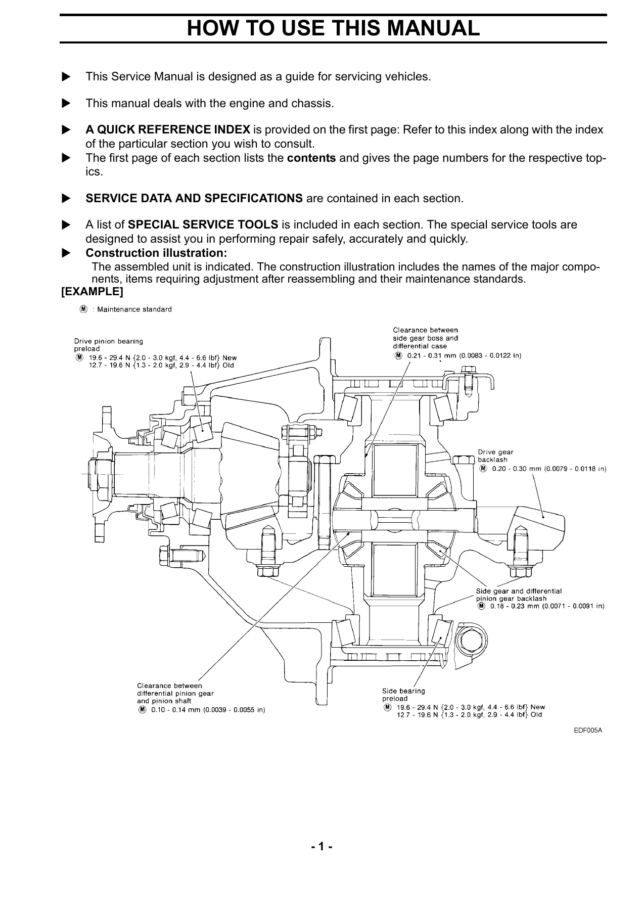
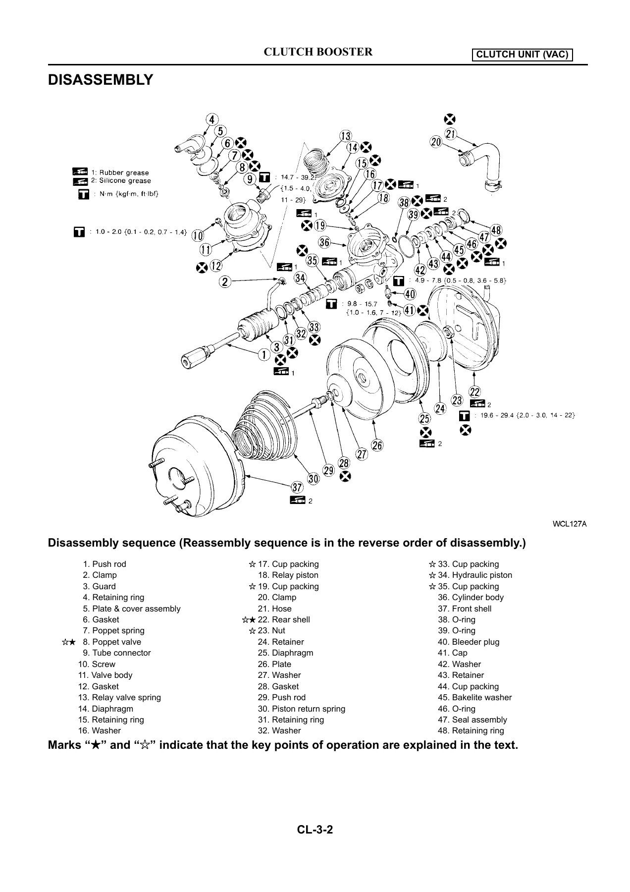
The document opens with a quick reference index that maps each chapter to its two-letter section prefix, then explains its own conventions. Every unit gets two illustrations. The construction illustration shows the assembled unit with the names of major components, the items that need adjustment after reassembly, and their maintenance standards. The exploded illustration numbers every part, and that number matches the part name in the accompanying sequence list, where the number order is also the disassembly order. Reassembly runs in reverse.
Where a step needs special attention, the part number carries a star mark and the text explains the precaution, the technique or the special tool. Grease points, oil points, sealing points and parts that must always be replaced after every disassembly are each marked with their own symbol. Torque figures appear in the illustrations in N·m with kgf·m and ft·lbf equivalents in braces. The manual works in SI units, with metric and yard/pound equivalents supplied throughout.
Two conventions matter in daily use. A maintenance standard is the clearance or performance expected when parts are correctly assembled. A service limit is the point at which adjustment, correction or replacement becomes mandatory. The manual is explicit that parts still inside the service limit may sometimes be worth replacing early from a preventive maintenance standpoint — useful guidance when a truck is already apart.
What This Chassis Manual Covers in Practice
The clutch chapter goes well beyond a disc change. It splits into the two operating systems used across the range, the vacuum servo units CL130, CL205 and CL207 and the air servo units CL710, CL740, CL750 and CL810, and then treats the booster and master cylinder as separate serviceable assemblies. Clutch disc runout limits, facing thickness above the rivet head, spline play, pressure plate flatness and contact surface thickness, diaphragm spring height and height difference, release lever and lever plate wear, release shaft outside diameter — all measured and specified.
Transmission coverage runs through the MHS, MLS and MPS families individually, each with its own construction views, disassembly sequence, inspection tables and reassembly notes. Backlash for each gear pair, end play for each main gear, reverse idler gear end play, radial play between hubs, sleeves and clutch gear splines, synchronizer ring clearance, strut clearance, detent spring tensions and shift fork to sleeve groove clearance are all laid out per transmission model. The PTO section covers the air shift and vacuum shift types with their own gear backlash, idler gear end play, cylinder and piston clearance, shift fork clearance and return spring data.
The differential chapter handles the SRHF-3, SRHH-2, SRHL, SRHL-1 and ITHL carriers in turn. Because hypoid gear setup is where most rebuilds go wrong, the manual includes the full gear contact pattern adjustment procedure — how to read a red lead contact pattern, what a pattern toward the toe or heel of the tooth means, what a pattern high or low on the tooth tells you, and which shim or adjusting nut to change in response. It also gives the tooth contact pattern diagrams alongside the adjustment procedure so the reading can be compared directly.
Brakes receive the largest share of the book. Separate chapters cover the brake proper for each wheel brake unit fitted across the range, then the vacuum servo brake unit, the air over hydraulic brake unit and the full air brake unit, then the parking brake. Air booster, brake valve models E6-R15, E6-RP1, E6-RP4, E6-ERP1, air pressure governor, air dryer models DR-5, DR-31, DR-41 and DR-42, parking brake valve, trailer brake hand control valve, quick release valve, double check valve, protection valve, load sensing proportion valve in both chain and leaf spring types, relay valve, 2-way relay valve, synchro valve, air brake chambers and Anchorlok spring brake chambers are all covered as individual serviceable units.
Why It Matters
Chassis work on trucks of this class is unforgiving of guesswork. A differential set up by feel rather than by measured backlash and a checked contact pattern will howl and then fail. A brake chamber push rod stroke left out of specification changes stopping distance across the whole vehicle. A kingpin shimmed by eye produces steering that never tracks straight. This manual replaces the guesswork with numbers, and it tells you how each number is obtained — where to place the feeler gauge, how far along the pitman arm to measure backlash, what load to apply when reading a bearing preload, how many notches to back an adjuster off from zero clearance.
It is equally useful for the working technician and for the operator running a small fleet. The maintenance schedule and lubrication interval tables, the periodic parts replacement chart organised by years of service, the grease lubrication point diagrams and the trouble diagnosis flow charts for symptoms such as unusual noise, poor acceleration, vibration, uneven braking or a steering wheel that fails to return — all of it is aimed at finding the fault before it becomes a roadside failure.
Get the Manual
This Nissan Diesel MK, LK, PK, CDA and CWA Series Truck Chassis Service Manual delivers the full chassis repair and diagnostic reference in a single PDF. Use it to service a clutch, overhaul a transmission, rebuild a differential carrier, reset wheel alignment, adjust brake lining clearance or push rod stroke, trace an electrical fault through the harness diagrams, or work through the heater and air conditioning systems.
IMAGES PREVIEW
The file is delivered by instant download after purchase. There is no shipping, no waiting, and no physical book to keep clean in the workshop. Open it on a laptop, tablet or phone at the vehicle, or print the pages you need for the job in front of you and take the paper to the truck. Keep the PDF on file and you have the complete chassis reference for the whole MK, LK, PK, CDA and CWA range available whenever a unit comes in.
Reviews
There are no reviews yet.