★ TRUSTED BY 321,897+ PROFESSIONALS WORLDWIDE
🏒
Trusted Business
Verified & Licensed
πŸ›‘οΈ
Virus Free Files
100% Safe Downloads
πŸ”’
Secure Payment
SSL Protected
⚑
Instant Delivery
Available Immediately
Sale!

Perkins 2800 Series 2806C-E16 2306 2806 Diesel Engine Workshop Manual

Original price was: $34.95.Current price is: $19.95.

Complete Perkins workshop manual for 2800 Series 2806C-E16 and 2306/2806 turbocharged diesel engines. 158 pages of service, repair, overhaul and specification data covering all major assemblies and systems.

⚑
Instant PDF Download
Available immediately
πŸ’Ύ
Save to Your Device
Download & keep forever
πŸ›‘οΈ
Antivirus Scanned
100% virus-free
🌍
Trusted Worldwide
175,000+ customers

Description

File Details

  • Manual type: Workshop Manual
  • Brand: Perkins
  • Series: 2300 Series and 2800 Series
  • Models covered: 2306, 2806, 2806C-E16
  • Engine application: 6-cylinder turbocharged diesel engines for industrial applications
  • Publication number: TSD3450E
  • Edition: Issue 2
  • Language: English
  • Page count: 158 pages
  • File format: PDF
  • Chapters: 1 through 16

Chapters Covered

The Perkins 2800 Series 2806C-E16 workshop manual is organised into sixteen chapters that move from general information through to special tools, covering every major assembly on the 2306 and 2806 engines. The contents below reflect the chapter headings and primary operation groups as printed in the manual’s table of contents.

  • 1 General information β€” Introduction, safety precautions, Viton seals, welding, environmental protection, engine views, engine identification, engine lift equipment
  • 2 Specifications β€” Basic engine data for 2306 and 2806 engines, rocker assemblies, valves, valve guides, valve springs, valve seat inserts, cylinder head, camshaft and bearings, pistons and connecting rods, crankshaft, main bearings, flywheel, crankshaft damper, crankcase and cylinder liners, lubricating oil pump, coolant pump, recommended torque figures
  • 3 Cylinder head assembly β€” Rocker cover, rocker lever and rocker shaft assemblies, tappet clearance adjustment, cylinder head removal and fitting, valve springs, valves, valve seals, valve guides, camshaft, camshaft gear backlash, electronic injector units, injector sleeves
  • 4 Pistons and connecting rod assemblies β€” Piston and connecting rod removal, dismantling and assembly, piston cooling jets
  • 5 Crankshaft assembly β€” Crankshaft removal and fitting, front and rear seal and wear sleeve renewal, crankshaft vibration damper
  • 6 Gear case and drive assembly β€” Gear case cover, timing gears, gear case removal and fitting, timing gear position check
  • 7 Crankcase and cylinder liners β€” Front engine support, cylinder liner removal and fitting, cylinder liner protrusion check and adjustment
  • 8 Engine timing and electronic controls β€” Electronic control module removal and fitting, engine timing check
  • 9 Aspiration system β€” Exhaust manifold, turbocharger removal, dismantling and assembly
  • 10 Lubrication system β€” Oil filter and oil filter header, sump, oil pump removal, dismantling and assembly
  • 11 Fuel system β€” Fuel priming pump, fuel transfer pump, drive for the fuel transfer pump, fuel filter header, low pressure fuel system air elimination
  • 12 Cooling system β€” Cooling system inspection and leakage test, coolant filler cap test, radiator, fan, fan drive assembly, fan drive belts, engine oil cooler, thermostats and thermostat housing, coolant temperature sensor, coolant pump
  • 13 Flywheel and housing β€” Flywheel removal and fitting, flywheel housing removal and fitting
  • 14 Electrical equipment β€” Starter motor, alternator, alternator belt tension and renewal
  • 15 Auxiliary equipment β€” Oil sample valve
  • 16 Special tools β€” Complete list of Perkins special tools referenced throughout the manual

Across its 158 pages, this Perkins 2800 Series workshop manual gives a technician the complete overhaul and service sequence for the 2306 and 2806 turbocharged diesel engines. Each chapter opens with a general information section and then presents numbered operations β€” remove and fit, dismantle and assemble, check and adjust β€” supported by illustrations, cross-references to the specifications chapter, and the special tool numbers needed for the job. The manual assumes the engine is out of the machine or accessible for major work; it is written for industrial applications of the 2800 Series, not for a specific vehicle installation.

Specifications and Torque Data

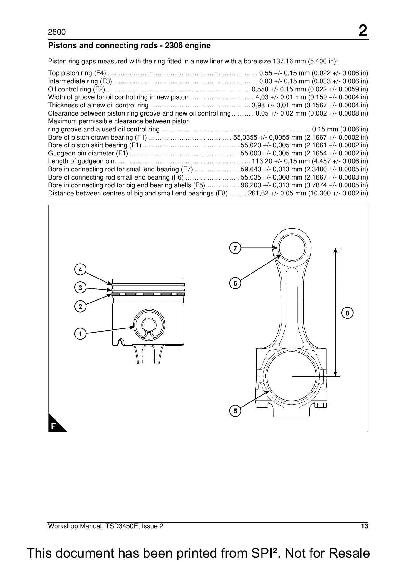
Chapter 2 of this Perkins 2806C-E16 manual is a full specification section covering the 2306 and 2806 engine variants side by side. It lists cylinder arrangement, cycle, induction and combustion system details, nominal bore and stroke, compression ratio, cubic capacity, firing order, direction of rotation, lubricating oil capacity and pressure, and typical coolant capacity for engine and radiator. Dimensional specifications are broken down for rocker assemblies, valve stems and heads, valve guides, valve springs, valve seat inserts, cylinder head thickness and flatness, camshaft journals and lobe lift, piston ring gaps, gudgeon pin and connecting rod bores, crankshaft main and connecting rod journals, main bearing clearances, crankshaft end-float, cylinder liner bore and flange thickness, crankcase bore centres, and crankshaft damper run-out.

Torque figures are provided for metric fasteners from M6 through M36, imperial fasteners from 1/4 inch through 1-1/2 inch, taperlock studs in both systems, O-ring face seal fittings, 37-degree flared fittings, 45-degree flared and inverted flare fittings, tapered pipe thread fittings, and standard hose clamps. A note in the manual explains that torque figures for nonferrous fittings should be halved.

Special Tools and Safety Content

Chapter 16 lists the complete set of Perkins special tools referenced by number throughout the operations β€” engine turning tools, cylinder liner installer and remover, piston ring compressors, camshaft guide and cradle tools, valve spring compressor, injector sleeve remover/installer, crankshaft seal locator and installer sets, pressurising pump for cooling system testing, and more. Each operation in the manual identifies the relevant special tools and consumable products at the start, so a technician can plan the job before starting.

Safety content in Chapter 1 covers general safety precautions, the 110-volt injector circuit warning, Viton seal handling, welding precautions around the ECM, and environmental protection guidance. These are Perkins’ own precautions for the 2800 Series and are repeated where relevant throughout the operation text.

Complete PDF Bookmark Tree

Complete Bookmarks

The complete bookmarks in the β€œPerkins 2800 Series 2806C-E16 2306 2806 Diesel Engine Workshop Manual” are as follows:

Perkins 2800 Seriesp. 1
Model 2806C-E16p. 1
Workshop manualp. 1
6 cylinder turbocharged diesel engines for industrial applicationsp. 1
Chaptersp. 2
1 General informationp. 2
2 Specificationsp. 2
3 Cylinder head assemblyp. 2
4 Piston and connecting rod assembliesp. 2
5 Crankshaft assemblyp. 2
6 Gear case and drive assemblyp. 2
7 Crankcase and cylinder linersp. 2
8 Engine timing and electronic controlsp. 2
9 Aspiration systemp. 2
10 Lubrication systemp. 2
11 Fuel systemp. 2
12 Cooling systemp. 2
13 Flywheel and housingp. 2
14 Electrical equipmentp. 2
15 Auxiliary equipmentp. 2
16 Special toolsp. 2
Publication TSD3450E, Issue 2p. 1
Β© Proprietary information of Perkins Engines Company Limited, all rights reserved.p. 1
The information is correct at the time of print.p. 1
Published in October 2002 by Technical Publications,p. 1
Perkins Engines Company Limited, Shrewsbury SY1 3NX, Englandp. 1
Contentsp. 3
1 General informationp. 3
Introduction 1p. 3
Safety precautions 2p. 3
Viton seals 4p. 3
Welding 4p. 3
Environmental protection 4p. 3
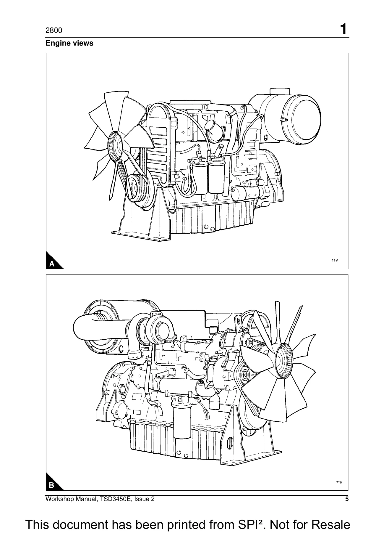
Engine views 5p. 3
Engine identification 6p. 3
Engine lift equipment 6p. 3
2 Specificationsp. 3
Basic engine data – 2306 engine 7p. 3
Basic engine data – 2806 engine 7p. 3
Rocker assemblies 8p. 3
Valves 9p. 3
Valve guides 10p. 3
Valve springs 10p. 3
Valve seat inserts 11p. 3
Cylinder head 12p. 4
Camshaft and bearings 12p. 4
Pistons and connecting rods – 2306 engine 13p. 4
Pistons and connecting rods – 2806 engine 14p. 4
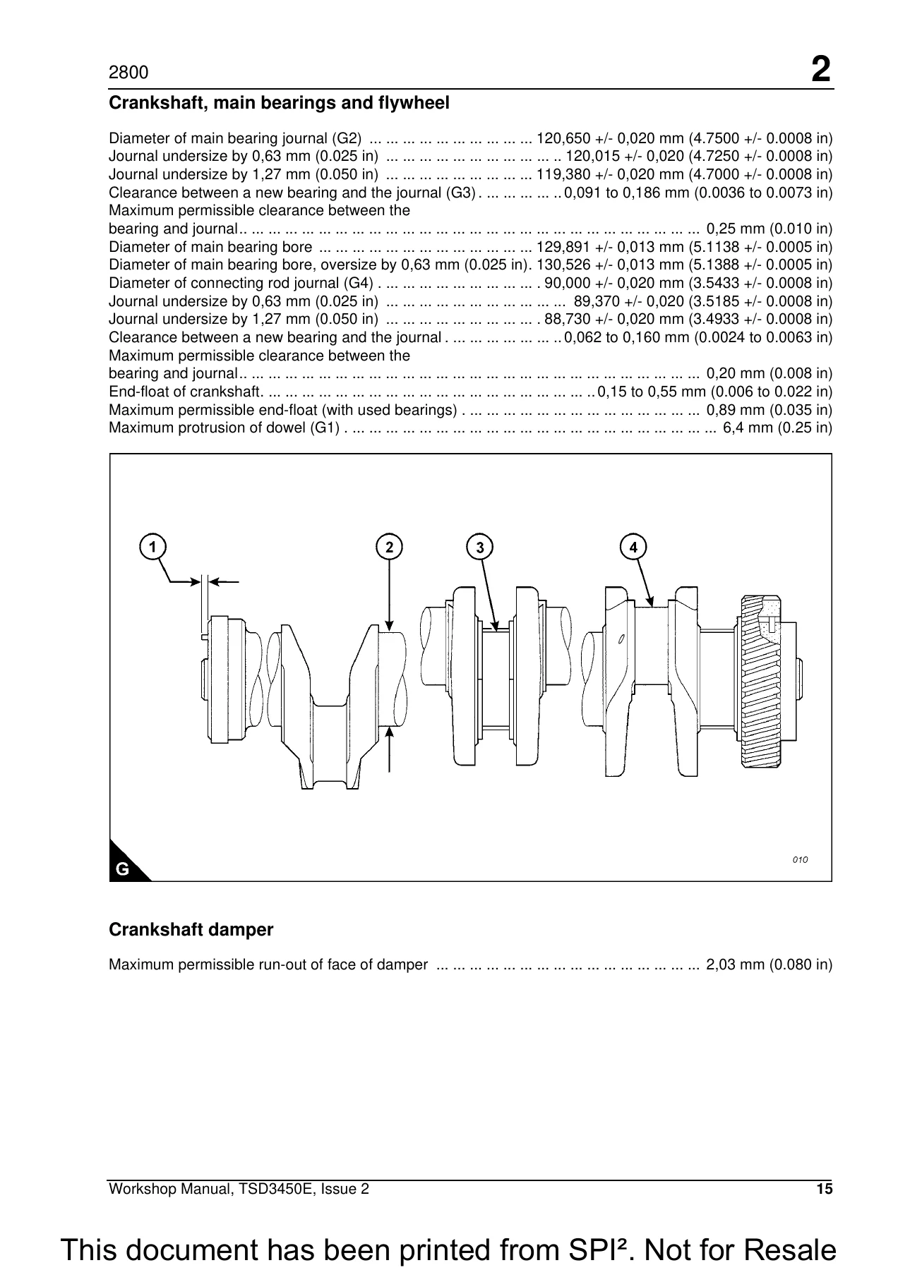
Crankshaft, main bearings and flywheel 15p. 4
Crankshaft damper 15p. 4
Crankcase and cylinder liners 16p. 4
Lubricating oil pump 18p. 4
Coolant pump 19p. 4
Recommended torque figures 20p. 4
3 Cylinder head assemblyp. 4
General information 27p. 4
4 Pistons and connecting rod assembliesp. 5
General information 57p. 5
5 Crankshaft assemblyp. 5
General information 63p. 5
6 Gear case and drive assemblyp. 5
General information 73p. 5
7 Crankcase and cylinder linersp. 6
General information 81p. 6
8 Engine timing and electronic controlsp. 6
General information 87p. 6
9 Aspiration systemp. 6
General information 91p. 6
10 Lubrication systemp. 7
General information 95p. 7
11 Fuel systemp. 7
General information 103p. 7
12 Cooling systemp. 7
General information 111p. 7
13 Flywheel and housingp. 8
General information 129p. 8
14 Electrical equipmentp. 9
General information 133p. 9
15 Auxiliary equipmentp. 9
General information 139p. 9
Oil sample valve 139p. 9
16 Special toolsp. 9
List of special tools 141p. 9
General informationp. 11
Introductionp. 11
Safety precautionsp. 12
Viton sealsp. 14
Weldingp. 14
Environmental protectionp. 14
Engine viewsp. 15
Engine identificationp. 16
Engine lift equipmentp. 16
Specificationsp. 17
Basic engine data – 2306 enginep. 17
Basic engine data – 2806 enginep. 17
Rocker assembliesp. 18
Valvesp. 19
Valve guidesp. 20
Valve springsp. 20
Valve seat insertsp. 21
Cylinder headp. 22
Camshaft and bearingsp. 22
Pistons and connecting rods – 2306 enginep. 23
Pistons and connecting rods – 2806 enginep. 24
Crankshaft, main bearings and flywheelp. 25
Crankshaft damperp. 25
Crankcase and cylinder linersp. 26
Lubricating oil pumpp. 28
Coolant pumpp. 29
Recommended torque figuresp. 30
Standard torque figures for metric fastenersp. 30
Metric nuts and boltsp. 30
Thread sizep. 30
metricp. 30
Standard torquep. 30
Metric taperlock studsp. 30
Thread sizep. 30
metricp. 30
Standard torquep. 30
Standard torque figures for imperial fastenersp. 31
Imperial nuts and boltsp. 31
Thread sizep. 31
inchesp. 31
Standard torquep. 31
Imperial taperlock studsp. 31
Thread sizep. 31
inchesp. 31
Standard torquep. 31
Standard torque figures for β€˜O’ ring face seal fittings and 37 degree flared fittingsp. 32
Torque figures for ferrous straight thread β€˜O’ ring fittings when connected to ferrous materialsp. 32
Outside diameter of nominal tubep. 32
Thread sizep. 32
Inchesp. 32
Standardp. 32
torquep. 32
β€˜O’ ring face seal fittingsp. 33
Torque figures for ferrous straight thread β€˜O’ ring fittings (B)p. 33
Thread sizep. 33
inchesp. 33
Standards torquep. 33
Torque figures for flared and β€˜O’ ring fittingsp. 34
Nuts for 37 degree flared fittingsp. 34
Outside diameter of nominal tubep. 34
Thread sizep. 34
Inchesp. 34
Standardp. 34
torquep. 34
45 degree flared and 45 degree inverted flare fittingsp. 35
Outside diameter of nominal tubep. 35
Thread sizep. 35
Inchesp. 35
Standardp. 35
torquep. 35
Tapered pipe thread fittingsp. 35
Thread sizep. 35
Inchesp. 35
Standard torquep. 35
Threads with pipe sealant (CV60891)p. 35
Threads without pipe sealantp. 35
Torque figures for standard hose clamps of the worm drive band typep. 36
Width of clampp. 36
Torque figure for initialp. 36
installation on a new hosep. 36
Torque figures for constant torque hose clampsp. 36
Cylinder head assemblyp. 37
General informationp. 37
Rocker coverp. 38
To remove and to fit Operation 3-1p. 38
1 Disconnect the wiring harness at the socket on the rocker cover (A1).p. 38
2 Disconnect and remove the engine breather pipe (A2).p. 38
3 Loosen fully the bolts which retain the rocker cover, but do not remove the bolts from the asse…p. 38
4 Remove the rocker cover.p. 38
1 Inspect the seal of the rocker cover and renew if worn of damaged.p. 38
2 Fit the rocker cover, complete with seal and bolts. Tighten the bolts to a torque of 20 Nm (15 …p. 38
3 Fit the engine breather pipe (A2).p. 38
4 Connect the wiring harness. Ensure that the wiring harness is fully engaged with the connector.p. 38
Rocker lever and rocker shaft assembliesp. 39
To remove and to fit Operation 3-2p. 39
1 Remove the rocker cover, Operation 3-1.p. 39
2 The valve rocker levers (A1) and the unit injector rocker levers (A2) can move on the shaft (A6…p. 39
3 Remove the four bolts (A5).p. 39
4 Remove the shaft (A6), valve rocker levers (A1) and unit injector rocker levers (A2) as a unit.p. 39
5 Repeat steps 1 and 2 for the rocker shaft assemblies which remain.p. 39
1 Loosen the adjustment screws (A3 and A4) of each of the rocker levers which have been removed. …p. 39
2 Set the tappet clearances, Operation 3-4.p. 39
3 Check/adjust the unit injectors, Operation 3-13.p. 39
4 Fit the rocker cover, Operation 3-1.p. 39
To dismantle and to assemble Operation 3-3p. 40
1 Slide the valve rocker levers (A3) and the unit injector rocker levers (A4) from the shaft (A7).p. 40
2 Remove the button (A1) from the adjustment screw (A2) in the valve rocker lever (A3).p. 40
3 Remove the button (A6) from the adjustment screw (A5) in the unit injector rocker lever (A4).p. 40
4 Repeat steps 1 to 3 for the rocker lever assemblies which remain.p. 40
1 Install new β€˜O’ ring seals in the buttons (A1).p. 41
2 Install new β€˜O’ ring seals in the buttons (A6).p. 41
3 To fit the β€˜O’ ring seals and buttons to the valve rocker levers, proceed as follows:p. 41
4 To fit the β€˜O’ ring seals and buttons to the unit injector rocker levers, proceed as follows:p. 41
5 Repeat steps 3 and 4 for the rocker levers which remain.p. 41
6 Fit the assembled rocker levers to the shafts (A7). Ensure that they are fitted to their origin…p. 41
How to check/adjust the tappet clearances Operation 3-4p. 42
Special toolsp. 42
Tappet clearancesp. 42
Descriptionp. 42
Part numberp. 42
Inletp. 42
Exhaustp. 42
1 Remove the rocker cover, Operation 3-1.p. 42
2 Remove the cover (A2) from the flywheel housing. The top bolt (A1) is the timing bolt.p. 42
3 Remove the plug (A3) from the timing bolt location in the flywheel housing and fit the timing b…p. 42
4 Insert the engine turning tool, CH11148, into the flywheel housing through the aperture behind …p. 42
5 Check the inlet and exhaust valves of the number 1 cylinder. If they are fully closed the pisto…p. 43
6 Before each set of tappet clearances is adjusted, ensure that the roller of the rocker lever is…p. 43
7 Use a set of feeler gauges, inserted at the position shown (B3) between the valve bridge piece …p. 43
8 After each unit has been adjusted, tighten the lock nut (B2) of the adjustment screw (B1) to a …p. 44
9 Withdraw the timing bolt and rotate the flywheel by 360 degrees so that the number 6 piston is …p. 44
10 Check the tappet clearances for the inlet valves (C1) on cylinders 3, 5 and 6. Adjust the clea…p. 44
11 After each unit has been adjusted, tighten the lock nut of the adjustment screw to a torque of…p. 44
12 Check again the tappet clearances for all six cylinders.p. 44
13 Fit the rocker cover. Remove the engine turning tool and the timing bolt and fit the cover to …p. 44
Cylinder head assemblyp. 45
To remove and to fit Operation 3-5p. 45
Special toolsp. 45
Consumable productsp. 45
Descriptionp. 45
Part numberp. 45
Descriptionp. 45
Part numberp. 45
1 Remove the thermostat housing, Operation 12-10.p. 45
2 Remove the exhaust manifold, Operation 9-1.p. 45
3 Remove the rocker lever and rocker shaft assemblies, Operation 3-2.p. 45
4 Remove the electronic unit injectors, Operation 3-12.p. 45
5 Remove the gear case cover, Operation 6-1.p. 45
6 Disconnect the cable and remove the timing sensor from the cylinder head.p. 45
7 Remove the support bracket which is fitted between the gear case and the cylinder head.p. 45
8 Remove one bolt from the camshaft gear and install the guide stud, GE50019. Remove the five bol…p. 45
9 Disconnect the fuel lines from the front and rear of the cylinder head. Fit temporary covers to…p. 45
10 Remove the cylinder head bolts; use the special socket, GE50020.p. 45
11 Fit the lifting bracket (A1), VP12712, to the cylinder head and attach a suitable hoist. Remov…p. 45
12 Remove the cylinder head gasket (B4).p. 46
13 Remove the β€˜O’ ring seal from the oil transfer tube (B6) and remove the 24 coolant seals (B3).p. 46
14 Remove the seal (B2).p. 46
15 Remove the spacer plate (B5) and discard the spacer plate gasket.p. 46
16 Remove the second β€˜O’ ring seal from the oil transfer tube (B6).p. 46
1 If the oil transfer tube (B6) has been removed, apply retaining compound, 21820 638, and insert…p. 47
2 If the rear dowel has been removed, apply retaining compound, 21820 638, and insert it in the c…p. 47
3 If the front dowel, close to the oil transfer tube, has been removed, it must be fitted in a dr…p. 47
4 Fit suitable guide studs (B1) to the cylinder block. Fit a new spacer plate gasket over the dow…p. 47
5 Fit a new β€˜O’ ring seal to the oil transfer tube (B6).p. 47
6 Fit the spacer plate (B5) and fit the second β€˜O’ ring seal to the oil transfer tube (B6). Fit t…p. 47
7 Check, and if necessary adjust, the protrusion of the cylinder liners, Operation 7-3.p. 47
8 Fit a new cylinder head gasket (B4) to the spacer plate.p. 47
9 Fasten a hoist to the cylinder head, use the lifting bracket VP12712, and lower the cylinder he…p. 48
10 Apply special lubricant, CV60895, to the washers, the threads and under the heads of the bolts…p. 48
11 Fit the camshaft gear. Check and, if necessary, adjust the backlash between the camshaft gear …p. 48
12 Fit the gear case cover, Operation 6-1.p. 48
13 Fit the support bracket between the cylinder head and the gear case.p. 48
14 Fit the electronic unit injectors, Operation 3-12.p. 48
15 Fit the rocker lever and shaft assemblies, Operation 3-2.p. 48
16 Fit the exhaust manifold, Operation 9-1.p. 48
17 Fit the thermostat housing, Operation 12-10.p. 48
18 Remove the covers from the fuel lines and from the fuel line ports on the cylinder head. Conne…p. 48
19 Fit the timing sensor and connect the cable.p. 48
Valve springsp. 49
To remove and to fit Operation 3-6p. 49
Special toolsp. 49
Descriptionp. 49
Part numberp. 49
1 Remove the rocker lever and rocker shaft assemblies, Operation 3-2.p. 49
2 Remove the electronic unit injectors, Operation 3-12.p. 49
3 Set the piston for the relevant valve spring assembly to the top of its compression stroke.p. 49
4 Use the hold-down clamp from the electronic unit injector to secure the valve spring compressor…p. 49
5 Insert the stud and base of the valve spring compressor into the bore of the injector sleeve. U…p. 49
6 Tighten the nut until the collets are loose on the valves.p. 49
7 Remove two collets from each valve.p. 49
8 Loosen slowly, then remove the nut, washer, thrust bearing and plate.p. 49
9 Remove the rotocoils, valve springs and washers from each valve.p. 49
10 Inspect the valve springs, refer to Chapter 2, Specifications for the correct dimensions and s…p. 49
11 Repeat steps 3 to 10 for the other valve spring assemblies which are to be removed.p. 49
1 Apply clean engine oil to the relevant valve stems.p. 50
2 Fit the washer, valve spring and rotocoil to each valve.p. 50
3 Use the valve spring compressor, GE50026, to compress the valve springs.p. 50
4 Fit two collets to each valve.p. 50
5 Loosen slowly and then remove the nut (A2) and plate (A1) of the valve spring compressor. Remov…p. 50
6 Tap lightly each valve with a soft hammer to ensure that the collets are seated correctly.p. 50
7 Fit the electronic unit injectors, Operation 3-12.p. 50
8 Fit the rocker lever and rocker shaft assemblies, Operation 3-2.p. 50
Valvesp. 51
To remove and to fit Operation 3-7p. 51
Special toolsp. 51
Descriptionp. 51
Part numberp. 51
1 Remove the cylinder head, Operation 3-5.p. 51
2 Put the cylinder head, flame face down, on a bench with a soft surface and release the valves b…p. 51
3 Withdraw the valves from the cylinder head.p. 51
4 Repeat the procedure for all valves which are to be removed.p. 51
1 Apply clean engine oil to the stems of the valves. Fit the valves to their original positions i…p. 51
2 Use the special tool, GE50026, and the procedure given in Operation 3-6, to install the valve s…p. 51
3 Fit the cylinder head, Operation 3-5.p. 51
Valve sealsp. 52
To renew Operation 3-8p. 52
Special toolsp. 52
Descriptionp. 52
Part numberp. 52
1 Remove the relevant valve spring assembly, Operation 3-6.p. 52
2 Remove the valve seal from the valve and valve guide.p. 52
3 Apply a thin film of clean engine oil to the new valve seal and slide the seal over the valve s…p. 52
4 If the valve seal is to be fitted to a valve guide with the valve removed, fit the seal to the …p. 52
5 Use the special tool, GE50027, and hand pressure only to push the valve seal into its position …p. 52
6 Withdraw the tool and fit the valve spring assembly, Operation 3-6.p. 52
Valve guidesp. 53
To remove and to fit Operation 3-9p. 53
Special toolsp. 53
Descriptionp. 53
Part numberp. 53
1 Remove the cylinder head, Operation 3-5.p. 53
2 Remove the valves, Operation 3-7.p. 53
3 Use the special tool (A1), GE50043, and a hammer to drive the valve guide (A2) from the cylinde…p. 53
1 Apply clean engine oil to the outside diameter of the new valve guides.p. 54
2 Use the special tool (B1), GE50043, together with the sleeve (B2), GE50044, to install the valv…p. 54
3 When a new valve guide has been fitted, check that there is full contact between the valve and …p. 54
4 Fit the valves, Operation 3-7.p. 54
5 Fit the cylinder head, Operation 3-5.p. 54
Camshaftp. 55
To remove and to fit Operation 3-10p. 55
Special toolsp. 55
Consumable productsp. 55
Descriptionp. 55
Part numberp. 55
Descriptionp. 55
Part numberp. 55
1 Remove the radiator, Operation 12-4.p. 55
2 Remove the fan, Operation 12-5.p. 55
3 Remove the gear case cover, Operation 6-1.p. 55
4 Remove the rocker cover, Operation 3-1.p. 55
5 Remove the rocker lever and shaft assemblies, Operation 3-2.p. 55
6 Remove the cover (A2) from the flywheel housing. The top bolt (A1) is the timing bolt.p. 55
7 Remove the plug (A3) from the timing bolt location in the flywheel housing and fit the timing b…p. 55
8 Insert the engine turning tool, CH11148, into the flywheel housing through the aperture behind …p. 56
9 Disconnect the lead and remove camshaft timing sensor from behind the top of the gear case.p. 56
10 Remove one bolt from the camshaft gear and install the guide stud, GE50019. Remove the five bo…p. 56
11 Attach a hoist to the camshaft gear and withdraw the gear from the camshaft. Remove the guide …p. 56
12 Remove three bolts and withdraw the thrust plate, the adaptor plate and the seal assembly.p. 56
13 Use the bolts of the rocker shaft to retain the cradle tool (B1), GE50018, at the position sho…p. 56
14 Remove the rear cover (C1), complete with seal (C3).p. 57
15 Fit the camshaft guide (D1), GE50017, to the gear case. Do not tighten the bolts for the guide…p. 57
16 Install a pilot tool, GE50015, into the threaded hole at the rear end of the camshaft. Then at…p. 57
17 Withdraw the camshaft until it enters the bore of the camshaft guide. Tighten the bolts which …p. 57
18 Use the lifting hooks, GE50025, to move the camshaft toward the front of the engine.p. 57
19 Withdraw the camshaft from the cylinder head just enough for a strap and hoist to be attached….p. 57
1 Fit the two pilot tools, GE50015, to the rear end of the camshaft. Ensure that the camshaft and…p. 58
2 Fit the camshaft guide (E1), GE50017, to the gear case cover, but do not tighten the bolts fully.p. 58
3 Insert the alignment sleeve (E2), GE50016, through the camshaft guide (E1) and into the camshaf…p. 58
4 Fit the cradle tool (F1), GE50018, at the position shown (F).p. 58
5 Use a suitable strap and hoist to support the camshaft. Insert the camshaft through the guide a…p. 58
6 Remove the strap and hoist. Rotate the camshaft during installation. Do not allow the end of th…p. 58
7 Remove the pilot tools and push the camshaft fully into its bore.p. 58
8 Inspect the seal (G3) and renew if necessary. Fit the rear cover (G1), complete with seal (G3).p. 58
9 Remove the cradle tool and the camshaft guide.p. 59
10 Fit new β€˜O’ ring seals to the camshaft front seal plate. Apply a small amount of engine lubric…p. 59
11 Fit the guide stud, GE50019, to the camshaft.p. 59
12 Fit the camshaft gear; align the hole in the gear with the dowel pin on the adapter plate. If …p. 59
13 Fit the bolts which retain the gear, remove the guide stud and fit the bolt which remains. Tig…p. 59
14 Fit the camshaft timing sensor to its location behind the top of the gear case and connect the…p. 59
15 Fit the gear case cover, Operation 6-1.p. 59
16 Remove the timing bolt from the flywheel and fit the cover and plug.p. 59
17 Install the rocker lever and shaft assemblies, Operation 3-2.p. 59
How to set the backlash for the camshaft gear Operation 3-11p. 60
1 Remove the main idler gear (A3). Hold the camshaft gear stationary and use a dial test indicato…p. 60
2 Fit the main idler gear (A3), hold the main idler gear stationary and measure the backlash on t…p. 60
3 To adjust the backlash, remove the three bolts and thrust plate which retain the adjustable idl…p. 60
4 Fit the idler gear. Retain with the thrust plate and three bolts. Check again the backlash betw…p. 60
5 When the correct backlash settings have been obtained, remove the adjustable idler gear and pro…p. 60
Electronic injector unitsp. 61
To remove and to fit Operation 3-12p. 61
Special toolsp. 61
Descriptionp. 61
Part numberp. 61
Descriptionp. 61
Part numberp. 61
1 Remove the relevant rocker shaft assembly, Operation 3-2.p. 61
2 Loosen the two nuts and remove the electrical connector from the injector unit.p. 61
3 Mark the valve bridge pieces to assist during assembly, then remove them.p. 61
4 Remove the bolt (A2) from the spacer and clamp which retain the injector unit and use the speci…p. 61
5 Remove the injector unit, together with the spacer and clamp.p. 61
6 Use the vacuum pump, GE50028, together with the tube, GE50030, and bottle, GE50029, to extract …p. 61
1 Clean thoroughly the bore of the injector sleeve and cylinder head. Use the special brushes (GE…p. 62
2 Check the condition of the β€˜O’ ring seals (B1 and B2); renew the seals if they are worn or dama…p. 62
3 Fit the injector unit to the cylinder head. Fit the clamp, spacer and retaining bolt. Tighten t…p. 62
4 Fit the bridge pieces.p. 62
5 Attach the electrical connector to the injector unit and retain with the two nuts. Tighten the …p. 62
6 Fit the rocker shaft assembly, Operation 3-2.p. 62
To check and to adjust Operation 3-13p. 63
Special toolsp. 63
Descriptionp. 63
Part numberp. 63
1 With the rocker covers removed, set the number 1 piston to TDC (top dead centre) on its compres…p. 63
2 Use the fuel injector setting gauge, CH11149, to obtain the correct height for the fuel injecto…p. 63
3 Remove the timing bolt from the flywheel housing and rotate the flywheel by 360 degrees in the …p. 63
4 Check/adjust the height dimensions for the fuel injectors of cylinders 1, 2 and 4 as given in s…p. 63
Injector sleevesp. 64
To remove and to fit Operation 3-14p. 64
Special toolsp. 64
Descriptionp. 64
Part numberp. 64
Descriptionp. 64
Part numberp. 64
1 Remove the rocker shaft assemblies, Operation 3-2.p. 64
2 Remove the electronic injector units, Operation 3-12.p. 64
3 Mark the bridge pieces and make a note of their position to assist during assembly, then remove…p. 64
4 Fit the puller stud from the special tool, GE50021, into the injector sleeve as shown (A). Fit …p. 64
5 Remove the β€˜O’ ring seals from the injector sleeve. Check the condition of the injector sleeve …p. 64
6 Repeat steps 1 to 5 for the injector sleeves which remain.p. 64
1 Use the brushes, special tool numbers: GE50023, GE50024 and GE50022, to clean thoroughly the bo…p. 65
2 Fit new β€˜O’ ring seals to the injector sleeve.p. 65
3 Fit the stud from the special tool into the threads of the injector sleeve.p. 65
4 Apply CV60889 anti-seize compound to the β€˜O’ ring seals and to the large diameter (B1) off the …p. 65
5 Apply CV60893 retaining compound to the small diameter (B2) off the injector sleeve.p. 65
6 Using the stud, insert the injector sleeve into its bore in the cylinder head. Take care to pre…p. 65
7 Fit the driver tool over the stud and tap lightly with a hammer to ensure that the injector sle…p. 65
8 Use a clean cloth to remove any retaining or anti-seize compound from the bores of the cylinder…p. 65
9 Fit the electronic injector units, Operation 3-12.p. 65
10 Fit the rocker shaft assemblies, Operation 3-2.p. 65
Pistons and connecting rod assembliesp. 67
General informationp. 67
Pistons and connecting rod assembliesp. 68
To remove and to fit Operation 4-1p. 68
Special toolsp. 68
Consumable productsp. 68
Descriptionp. 68
Part numberp. 68
Descriptionp. 68
Part numberp. 68
1 Remove the cylinder head assembly, Operation 3-5.p. 68
2 Remove the oil pump, Operation 10-4.p. 68
3 Remove the stiffener plate from the base of the crankcase.p. 68
4 Remove the carbon ridge from the top inside surface of the cylinder liners.p. 68
5 Turn the crankshaft until two pistons are at bottom centre.p. 68
6 Remove the bolts (A1) and the bearing caps. Push the connecting rods and pistons up until the r…p. 68
7 Withdraw carefully the pistons and connecting rods from the cylinder liners. Store the bearing …p. 68
8 Repeat steps 3 to 6 for the remainder of the pistons and connecting rods.p. 68
1 Apply clean engine oil to the piston rings, the connecting rod bearings and the cylinder liners.p. 69
2 Ensure that the piston ring gaps are set at 120 degree intervals to each other.p. 69
3 Use the special tool (B1), GE50003 for 2806 engines or GE50045 for 2306 engines, to install the…p. 69
4 Fit the bearing cap to the connecting rod. The cap must be fitted with its number on the same s…p. 69
5 Apply anti-seize compound, CV60890, to the bolt threads. Install the bolts and bearing cap. Tig…p. 69
6 Repeat steps 1 to 4 for the remainder of the pistons and connecting rods.p. 69
7 Fit the stiffener plate to the base of the crankcase.p. 69
8 Fit the oil pump, Operation 10-4.p. 69
9 Fit the cylinder head assembly, Operation 3-5.p. 69
To dismantle and assemble Operation 4-2p. 70
1 Remove the pistons and connecting rod assemblies, Operation 4-1.p. 70
2 Remove the big-end bearing shells (A5) from the connecting rod (A4) and connecting rod cap. If …p. 70
3 Remove the circlips (A1).p. 70
4 Remove the gudgeon pin (A2) and separate the connecting rod and the piston crown from the piston.p. 70
5 Remove carefully the piston rings (A3) from the piston crown and clean the piston ring grooves …p. 70
1 Check the gaps between the ends of the piston rings when the rings are inserted in a new liner….p. 71
2 Fit the spring of the oil control ring to its groove in the piston crown.p. 71
3 Use a suitable piston ring expander to fit the oil control ring to its groove in the piston crown.p. 71
4 Fit the second (intermediate) piston ring with the side that has the identification "UP-2" towa…p. 71
5 Fit the first (top) piston ring with the side that has the identification "UP-1" toward the top…p. 71
6 When all three piston rings have been fitted, adjust the position of the piston ring gaps so th…p. 71
7 Fit the piston crown into the piston skirt and insert the connecting rod. Apply clean engine oi…p. 71
8 Fit the big-end bearings to the connecting rod (A4) and connecting rod cap. If the original bea…p. 71
9 Fit the pistons and connecting rod assemblies, Operation 4-1.p. 71
Piston cooling jetsp. 72
To remove and to fit Operation 4-3p. 72
Special toolsp. 72
Descriptionp. 72
Part numberp. 72
1 Remove oil pump, Operation 10-4.p. 72
2 Use the engine turning tool, CH11148, to turn the crankshaft in a clockwise direction (as seen …p. 72
3 Remove the bolt which retains the cooling jet and remove the cooling jet from the engine.p. 72
4 Repeat steps 2 and 3 for the cooling jets which remain.p. 72
1 Before a piston cooling jet is fitted to the engine, use the jet alignment tool, GE50004, to en…p. 72
2 Carefully fit the piston cooling jets to the engine, ensure that the nozzles of the cooling jet…p. 72
3 Fit the oil pump, Operation 10-4.p. 72
Crankshaft assemblyp. 73
General informationp. 73
Crankshaftp. 74
To remove and to fit Operation 5-1p. 74
Consumable productsp. 74
Descriptionp. 74
Part numberp. 74
1 Remove the gear case cover, Operation 6-1.p. 74
2 Remove the flywheel housing, Operation 13-2.p. 74
3 Remove the pistons and connecting rod assemblies, Operation 4-1.p. 74
4 Remove the crankshaft rear seal and wear sleeve, Operation 5-3.p. 74
5 Remove the crankshaft front seal and wear sleeve, Operation 5-2.p. 74
6 Remove the bolts (A1) which retain the main bearing caps in the crankcase and remove the bearin…p. 74
7 Fit one of the bolts from the front pulley to each end of the crankshaft. Fasten a hoist to the…p. 74
1 Clean the crankcase and the main bearing caps thoroughly. Apply clean engine oil to the main be…p. 75
2 Install one of the bolts from the front pulley in each end of the crankshaft, fasten a suitable…p. 75
3 Fit the thrust bearings for the centre main bearing. Ensure that the bearings are fitted with t…p. 75
4 Fit the main bearings to the bearing caps.p. 75
5 Ensure that the tabs on the back of the bearing shells fit into the tab slots of the bearing ca…p. 75
6 Apply anti-seize compound, CV60890, to the bolts and install the main bearing caps and bolts.p. 75
7 Begin at the tab end of the bearing cap first, tighten each bearing cap bolt to a torque of 260…p. 75
8 Use a dial test indicator (DTI) to check the end-float of the crankshaft. Ensure that the point…p. 75
9 Fit the crankshaft front seal and wear sleeve, Operation 5-2.p. 75
10 Fit the crankshaft rear seal and wear sleeve, Operation 5-3.p. 75
11 Fit the pistons and connecting rod assemblies, Operation 4-1.p. 75
12 Fit the flywheel housing, Operation 13-2.p. 75
13 Fit the gear case cover, Operation 6-1.p. 75
Crankshaft front seal and wear sleevep. 76
To renew Operation 5-2p. 76
Special toolsp. 76
Consumable productsp. 76
Descriptionp. 76
Part numberp. 76
Descriptionp. 76
Part numberp. 76
1 Remove the vibration damper, Operation 5-4.p. 76
2 Drill three holes (A2) at an equal distance around the circumference of the seal. Fit self-tapp…p. 76
3 Fit the distorter protection ring (B1), GE50010, to the seal bore and at the same depth as the …p. 76
4 Insert the distorter tool (B2), GE50011, between the protection ring and the wear sleeve. With …p. 76
5 Remove the distorter tool, the protection ring and the wear sleeve.p. 76
1 Clean and the wear sleeve inside diameter and crankshaft outside diameter with quick cure prime…p. 77
2 Use the bolts (C3), GE50009, to install the guide, GE50008, on the crankshaft.p. 77
3 Fit the wear sleeve and seal (C4) as a unit onto the locator, GE50008.p. 77
4 Fit the installer (C2), GE50012, onto the locator.p. 77
5 Apply clean engine oil to the face of the nut (C1), GE50014, and to its contact area on the ins…p. 77
6 Fit the nut to the locator and tighten the nut until the inside surface of the installer is in …p. 77
7 Remove all of the tools from the crankshaft.p. 77
8 Fit the vibration damper, Operation 5-4.p. 77
Crankshaft rear seal and wear sleevep. 78
To renew Operation 5-3p. 78
Special toolsp. 78
Consumable productsp. 78
Descriptionp. 78
Part numberp. 78
Descriptionp. 78
Part numberp. 78
1 Remove the flywheel, Operation 13-1.p. 78
2 Drill three holes (A2) at an equal distance around the circumference of the seal. Fit self-tapp…p. 78
3 Fit the distorter protection ring (B1), GE50010, to the seal bore and at the same depth as the …p. 78
4 Insert the distorter tool (B2), GE50011, between the protection ring and the wear sleeve. With …p. 78
5 Remove the distorter tool, the protection ring and the wear sleeve.p. 78
1 Clean and the wear sleeve inside diameter and crankshaft outside diameter with quick cure prime…p. 79
2 Use the bolts (C4), GE50009, to install the guide, GE50008, on the crankshaft.p. 79
3 Fit the wear sleeve and seal (C3) as a unit onto the locator, GE50008.p. 79
4 Fit the installer (C2), GE50012, onto the locator.p. 79
5 Apply clean engine oil to the face of the nut (C1), GE50014, and to its contact area on the ins…p. 79
6 Fit the nut to the locator and tighten the nut until the inside surface of the installer is in …p. 79
7 Remove all of the tools from the crankshaft.p. 79
8 Fit the flywheel, Operation 13-1.p. 79
Crankshaft vibration damperp. 80
To remove and to fit Operation 5-4p. 80
1 Remove the fan guards.p. 80
2 Slacken the tension on the fan drive belts, then remove the belts from the crankshaft pulley (A1).p. 80
3 Attach a strap and a suitable lifting device to the vibration damper (A2). Remove the six bolts…p. 80
4 Remove damper and adapter. The weight of the vibration damper is approximately 25 kg (55 lb).p. 80
1 Attach a strap and a suitable lifting device to the vibration damper (A2). Use a 5/8 -18 x 6 in…p. 81
2 Fit the crankshaft pulley (A1). Apply clean engine oil to the threads of the bolts and install …p. 81
3 Remove the guide stud and install the final bolt and washer. Tighten the bolts to a torque of 2…p. 81
4 Fit the fan belts and adjust the tension as given in Operation 12-7.p. 81
5 Fit the fan guards.p. 81
Gear case and drive assemblyp. 83
General informationp. 83
Gear case coverp. 84
To remove and to fit Operation 6-1p. 84
1 Remove the radiator, Operation 12-4.p. 84
2 Remove the fan, Operation 12-5.p. 84
3 Loosen the bolts which retain the gear case cover. Do not remove the bolts from the assembly, a…p. 84
4 Remove the gear case cover.p. 84
1 Examine the seal and renew if necessary, clean the contact surfaces of the seal and the gear case.p. 84
2 Fit the gear case cover and tighten the bolts, in the sequence shown (A), to a torque of 20 Nm …p. 84
3 Fit the fan, Operation 12-5.p. 84
4 Fit the radiator, Operation 12-4.p. 84
Timing gearsp. 85
To remove and to fit Operation 6-2p. 85
Special toolsp. 85
Consumable productsp. 85
Descriptionp. 85
Part numberp. 85
Descriptionp. 85
Part numberp. 85
1 Remove the gear case cover, Operation 6-1, and set the engine to the correct timing position fo…p. 85
2 Remove the top bolt (A1) from the cover (A2) on the flywheel housing and loosen the other cover…p. 85
3 Remove the plug (A3) from the timing bolt location in the flywheel housing and fit the timing b…p. 85
4 Insert the engine turning tool, CH11148, into the flywheel housing through the aperture behind …p. 85
5 Remove the rocker lever and rocker shaft assemblies, Operation 3-2. If the camshaft gear (C2) i…p. 86
6 Remove the camshaft gear (C2), if relevant. Use the guide stud, GE50019. If the gear case is to…p. 86
7 Remove the three bolts and the thrust plate (C3) and remove the adjustable idler. Discard the b…p. 86
8 Check the condition of the bearing in the gear. Renew the bearing if it is worn or damaged.p. 86
9 Remove the three bolts and the thrust plate (C4) and remove the main idler. Discard the bolts.p. 86
10 Check the condition of the bearing in the gear. Renew the bearing if it is worn or damaged.p. 86
11 Remove the four bolts and the thrust plate (C1) and withdraw the compound idler. Discard the b…p. 86
12 Check the condition of the bearing in the gear. Renew the bearing if it is worn or damaged.p. 86
13 Check the condition of the shaft for the adjustable idler. If the bearing diameter of the shaf…p. 86
14 Check the condition of the shaft for the main idler. If the bearing diameter of the shaft is w…p. 86
15 Check the condition of the shaft for the compound idler. Renew the shaft if the bearing diamet…p. 86
1 Fit the assembly of the compound idler to its shaft, ensure that the "V" timing mark on the cra…p. 87
2 Fit the main idler gear to the shaft assembly. Fit the thrust plate and fit new bolts. Apply th…p. 87
3 Fit the adjustable idler gear to the shaft assembly. Fit the thrust plate and fit new bolts. Ap…p. 87
4 Fit the camshaft gear, if it was removed: align the hole in the gear with the dowel pin on the …p. 87
5 Fit the bolts which retain the gear, remove the guide stud and fit the bolt which remains. Tigh…p. 87
6 Fit the gear case cover, Operation 6-1.p. 87
7 Remove the timing bolt from the flywheel and fit the cover and plug.p. 87
8 Install the rocker lever and shaft assemblies, Operation 3-2.p. 87
How to check the position of the timing gears Operation 6-3p. 88
Gear casep. 89
To remove and to fit Operation 6-4p. 89
Consumable productsp. 89
Descriptionp. 89
Part numberp. 89
1 Remove the gear case cover, Operation 6-1.p. 89
2 Disconnect the lead and remove camshaft timing sensor from behind the top of the gear case.p. 89
3 Disconnect the lead and remove crankshaft timing sensor from behind the bottom of the gear case.p. 89
4 Remove the fan drive assembly, Operation 12-6.p. 89
5 Remove the coolant pump, Operation 12-13.p. 89
6 Remove the crankshaft vibration damper, Operation 5-4.p. 89
7 Remove the front engine support, Operation 7-1.p. 89
8 Remove the sump, Operation 10-3.p. 89
9 Remove the fuel transfer pump, Operation 11-2. If necessary, remove the drive for the fuel tran…p. 89
10 Remove the timing gears and the camshaft drive gear, Operation 6-2.p. 89
11 Remove the bolt and five nuts which retain the axle for the adjustable idler.p. 89
12 Remove the bolt and five nuts which retain the axle for the main idler.p. 89
13 Remove the three bolts which retain the camshaft front seal assembly. Remove the thrust plate,…p. 89
14 Attach a suitable hoist to the gear case and remove the mounting bolts.p. 89
15 Remove the gear case from the dowels in the crankcase. The weight of the gear case is approxim…p. 89
1 Clean thoroughly the contact surfaces of the crankcase and gear case.p. 90
2 Fit the two dowels, if they have been removed, and ensure that they protrude from the crankcase…p. 90
3 Ensure that the front surface of the crankcase is clean and fit a new joint to the crankcase.p. 90
4 Ensure that the rear face of the gear case is clean and fit the gear case onto the crankcase. F…p. 90
5 Check the condition of the shaft for the adjustable idler. If the bearing diameter of the shaft…p. 90
6 Check the condition of the shaft for the main idler. If the bearing diameter of the shaft is wo…p. 90
7 Check the condition of the shaft for the compound idler. Renew the shaft if the bearing diamete…p. 90
8 Fit new β€˜O’ ring seals to the camshaft front seal plate. Apply a small amount of engine lubrica…p. 90
9 Fit the timing gears, Operation 6-2.p. 90
10 Fit the sump, Operation 10-3.p. 90
11 Fit a new crankshaft front seal and wear sleeve, Operation 5-2.p. 90
12 Fit the front engine support, Operation 7-1.p. 90
13 Fit the crankshaft vibration damper, Operation 5-4.p. 90
14 Fit the coolant pump, Operation 12-13.p. 90
15 Fit the camshaft timing sensor to its location behind the top of the gear case and connect the…p. 90
16 Fit the crankshaft timing sensor to its location behind the bottom of the gear case and connec…p. 90
17 Fit the gear case cover, Operation 6-1.p. 90
Crankcase and cylinder linersp. 91
General informationp. 91
Front engine supportp. 92
To remove and to fit Operation 7-1p. 92
1 Remove the radiator, Operation 12-4.p. 92
2 Use a suitable hoist, attached to the front lifting bracket, to support the engine and remove t…p. 92
3 Remove the eight bolts and washers (A1) and remove the engine support.p. 92
1 Fit the front engine support to the engine and retain with eight bolts and washers (A1).p. 92
2 Attach the engine support to the base frame with the relevant bolts (A2), remove the hoist from…p. 92
3 Fit the radiator, Operation 12-4.p. 92
Cylinder linersp. 93
To remove and to fit Operation 7-2p. 93
Special toolsp. 93
Consumable productsp. 93
Descriptionp. 93
Part numberp. 93
Descriptionp. 93
Part numberp. 93
1 Remove the pistons and connecting rod assemblies, Operation 4-1.p. 93
2 Fit covers over the journals of the crankshaft for protection from dirt or water.p. 93
3 Use the special tool (A1), GE50001, to remove the cylinder liners (A2). Make a note of the bore…p. 93
1 Clean the cylinder liners and the liner bores in the crankcase.p. 93
2 Install the cylinder liners in the cylinder block without the β€˜O’ ring seals or the filler band…p. 93
3 Check the protrusion of the cylinder liners, Operation 7-3.p. 93
4 Remove the liners and fit new β€˜O’ ring seals.p. 93
5 When the engine is ready for final assembly, the β€˜O’ ring seals, the cylinder block and the upp…p. 93
6 After the engine oil or liquid soap has been applied, immerse the filler band in clean engine o…p. 93
7 Fit the pistons and connecting rod assemblies, Operation 4-1.p. 93
To check and to adjust the protrusion of the cylinder liners Operation 7-3p. 94
Special toolsp. 94
Descriptionp. 94
Part numberp. 94
Descriptionp. 94
Part numberp. 94
1 Ensure that the top face of the cylinder block (A4) is clean. Fit a new spacer plate gasket and…p. 94
2 Fit the cylinder liners to the cylinder block without seals or bands. Ensure that the cylinder …p. 94
3 Install all of the bolts (A6), GE50005, or the six bolts around the liner (A5) to be checked. A…p. 94
4 Use the special tool, GE50002, to measure the liner protrusion at the four positions shown (B1,…p. 94
5 Add the four readings for each cylinder and divide the sum of the readings by four to obtain th…p. 94
6 If the liner protrusions are all below the specifications or low in the range, 0,025 mm (0.001 …p. 95
7 When the liner protrusion is correct, add a temporary mark to the liner and to the spacer plate…p. 95
8 When the engine is ready for final assembly, the β€˜O’ ring seals, the cylinder block and the upp…p. 95
Engine timing and electronic controlsp. 97
General informationp. 97
Electronic control modulep. 98
To remove and to fit Operation 8-1p. 98
1 Switch off the engine and disconnect the electrical power supply.p. 98
2 Loosen fully the Allen screws from the J1 and J2 connectors (A1 and A4).p. 98
3 Remove the two nuts which retain the bar (A6) and the control module (A3), release the ground s…p. 98
4 Support the control module, remove the two remaining nuts (A2 and A5) and remove the electronic…p. 98
1 Fit the electronic control module. Retain with four nuts, ensure that the ground strap is fitte…p. 98
2 Fit the connectors (A1 and A4) and retain with Allen screws. Tighten the screws to a torque of …p. 98
3 Connect the electrical power supply.p. 98
Engine timingp. 99
To check Operation 8-2p. 99
Special toolsp. 99
Descriptionp. 99
Part numberp. 99
1 With the engine switched off and electrically isolated, remove the rocker cover, Operation 3-1.p. 99
2 Remove the cover (A2) from the flywheel housing. The top bolt (A1) is the timing bolt.p. 99
3 Remove the plug (A3) from the timing bolt location in the flywheel housing and fit the timing b…p. 99
4 Insert the engine turning tool, CH11148, into the flywheel housing through the aperture behind …p. 99
5 Attach a plunger clock and set the plunger on the top face of the rocker lever of the number on…p. 100
6 Rotate the engine in the normal direction of rotation until the timing bolt can again enter the…p. 100
7 Repeat step 6 to ensure that a consistent reading is obtained.p. 100
8 If the reading is not within the limits, adjust the position of the adjustable idler gear to ad…p. 100
Aspiration systemp. 101
General informationp. 101
Exhaust manifoldp. 102
To remove and to fit Operation 9-1p. 102
Special toolsp. 102
Consumable productsp. 102
Descriptionp. 102
Part numberp. 102
Descriptionp. 102
Part numberp. 102
1 Remove the turbocharger, Operation 9-2.p. 102
2 Remove the thermostat housing, Operation 12-10.p. 102
3 Remove the exhaust shield.p. 102
4 Remove the nuts and spacers which retain the exhaust manifold and remove the manifold.p. 102
5 Withdraw the sleeves from the cylinder head.p. 102
6 Remove the gaskets from the cylinder head.p. 102
1 Check the condition of all sleeves, studs and nuts. Renew the components if worn or damaged. Ap…p. 102
2 Fit new gaskets over the studs and install the sleeves. Fit the exhaust manifold, fit the space…p. 102
3 Fit the thermostat housing, Operation 12-10.p. 102
4 Fit the turbocharger, Operation 9-2.p. 102
Turbochargerp. 103
To remove and to fit Operation 9-2p. 103
1 Disconnect the exhaust pipe from the turbocharger.p. 103
2 Remove the air duct from between the turbocharger and the air cleaner.p. 103
3 Disconnect the air duct from between the turbocharger and the charge air cooler.p. 103
4 Disconnect the oil feed (A2) and oil drain (A1) pipes.p. 103
5 Use a strap and hoist to support the turbocharger, remove the four bolts which retain the turbo…p. 103
1 Fit the turbocharger to the exhaust manifold. Apply CV60889 anti-seize compound to the bolts. F…p. 103
2 Connect the oil feed and oil drain pipes (A2 and A1).p. 103
3 Fit the air duct between the turbocharger and the air cleaner.p. 103
4 Connect the air duct between the turbocharger and the charge air cooler.p. 103
5 Connect the exhaust pipe.p. 103
To dismantle and to assemble Operation 9-3p. 104
1 Remove turbocharger, Operation 9-2.p. 104
2 Add temporary alignment marks between the bearing housing and both the compressor housing and t…p. 104
3 Loosen the nuts on the clamps and separate the compressor housing and the turbine housing from …p. 104
4 Check the condition of all components. Renew any worn or damaged components.p. 104
1 Fit the compressor housing and the turbine housing to the bearing housing and retain with the r…p. 104
2 Adjust the position of both the compressor and turbine housings until the temporary marks are a…p. 104
3 Fit the turbocharger, Operation 9-2.p. 104
Lubrication systemp. 105
General informationp. 105
Oil filter and oil filter headerp. 106
To remove and to fit Operation 10-1p. 106
1 Remove the plug (A5) and drain the oil from the oil filter housing.p. 106
2 Remove the oil filter housing (A3), and remove the oil filter element.p. 106
3 Remove the four bolts (A1) which connect the oil filter header to the oil cooler.p. 106
4 Remove the two bolts (A2) which retain the oil filter header on the crankcase.p. 106
5 Disconnect the turbocharger oil supply pipe from the elbow behind the oil cooler.p. 106
6 Remove the four bolts which retain the assembly of the elbow and oil filter header on the crank…p. 106
7 Remove the four bolts to separate the oil filter header from the elbow. Renew the β€˜O’ ring seal…p. 106
1 Ensure that the β€˜O’ ring seals are fitted to the elbow. Assemble the elbow and oil filter heade…p. 107
2 Ensure that the used gasket material has been removed from the mating faces. Fit the assembly t…p. 107
3 Fit the four bolts (A1) which retain the oil filter header to the oil coolerp. 107
4 Connect the turbocharger oil supply pipe and tighten securely.p. 107
5 Clean the filter housing (A3) and clean the contact face of the filter head. Clean the drain pl…p. 107
6 Fit a new element into the filter housing, ensure that it engages fully with the guide in the b…p. 107
7 Fit the housing (A3) onto the filter head and tighten by use of a socket and torque wrench on t…p. 107
8 Check the amount of engine oil in the sump. If necessary, add more oil of the correct grade and…p. 107
9 Run the engine and check for leaks. Check again the amount of engine oil in the sump. If necess…p. 107
Oil filter headerp. 108
To dismantle and to assemble Operation 10-2p. 108
1 Remove the two plugs (A5 and A6) which retain the by-pass valves in the oil filter header (A1).p. 108
2 Remove the spring (A3) and the plunger (A2) for the oil cooler by-pass valve. Remove the spring…p. 108
3 Remove the two small plugs and the adaptor.p. 108
1 Fit the plunger (A9) and spring (A8) to the oil filter header.p. 108
2 Fit the plunger (A2) and spring (A3) to the oil filter header.p. 108
3 Fit the plugs (A5 and A6). Tighten each plug to 100 +/- 15 Nm (74 +/- 11 lbf ft).p. 108
4 Fit the adaptor and the two small plugs. Tighten each of them to 25 +/- 5 Nm (18 +/- 4 lbf ft).p. 108
Sumpp. 109
To remove and to fit Operation 10-3p. 109
Consumable productsp. 109
Descriptionp. 109
Part numberp. 109
1 Drain the oil from the sump (A2).p. 109
2 Loosen the bolts which retain the sump on the engine. Do not remove the bolts fully, allow them…p. 109
3 Remove the sump.p. 109
1 Examine the sump seal and renew if necessary. Ensure that the machined surface of the sump is c…p. 110
2 Clean the bottom face of the crankcase and also the bottom faces of the flywheel housing and th…p. 110
3 Apply a bead of RTV silicone sealant, CV60888, at the four positions where the edge of the flyw…p. 110
4 Fit the sump and tighten the bolts to a torque of 30 Nm (22 lbf ft); use the sequence shown (B).p. 110
5 Fill the engine to the correct level with oil of the correct grade and specification. Refer to …p. 110
Oil pumpp. 111
To remove and to fit Operation 10-4p. 111
1 Remove the sump, Operation 10-3.p. 111
2 Remove the oil supply tube (A3) and the strainer and tube (A2).p. 111
3 Remove the bolts and remove the oil pump (A4).p. 111
1 Fit the oil pump to the crankcase.p. 111
2 Apply clean engine oil to the β€˜O’ ring seals of the tubes.p. 111
3 Install oil supply tube (A3) and strainer and tube (A2).p. 111
4 Fit the sump, Operation 10-3.p. 111
To dismantle and to assemble Operation 10-5p. 112
1 Remove the bolt and washer which retain the gear on the shaft.p. 112
2 Use a suitable gear puller to remove drive gear (A1) from the shaft. Remove the key from the sh…p. 112
3 Remove retainer (A5) for the by-pass valve.p. 112
4 Remove the spring (A4) and the by-pass valve (A3).p. 112
5 Remove the cover (A6) from the pump body (A2).p. 112
6 Remove the idler gear and drive gear from pump body.p. 112
1 Apply clean engine oil to the idler gear and drive gear and install the gears in the oil pump b…p. 112
2 Fit the by-pass valve, the spring and the retainer to the pump body (A2).p. 112
3 Fit the key to the shaft.p. 112
4 Fit the drive gear (A1) to the shaft. Install the washer and bolt which retain the gear. Tighte…p. 112
Fuel systemp. 113
General informationp. 113
Fuel priming pumpp. 114
To remove and to fit Operation 11-1p. 114
1 Remove two bolts (A2) and remove fuel priming pump (A1).p. 114
1 Inspect the gasket of the fuel priming pump; fit a new gasket if necessary.p. 114
2 Fit the fuel priming pump (A1) and retain with the two bolts (A2).p. 114
Fuel transfer pumpp. 115
To remove and to fit Operation 11-2p. 115
1 Disconnect the fuel pipes from the fuel transfer pump (A2).p. 115
2 Use plugs or caps to seal temporarily all openings to prevent contamination of the fuel system.p. 115
3 Remove the bolts (A1) and withdraw the fuel transfer pump.p. 115
1 Check the condition of the β€˜O’ ring seal on the fuel transfer pump, renew the seal if it is wor…p. 115
2 Ensure that the β€˜O’ ring seal is fitted correctly to the fuel transfer pump. Apply a small amou…p. 115
3 Fit the fuel transfer pump (A2) and retain with two bolts (A1).p. 115
4 Remove the plugs or caps from the fuel pipe openings and connect the fuel pipes.p. 115
5 Eliminate air from the fuel system, Operation 11-6.p. 115
To test Operation 11-3p. 116
1 Run the pump at 2940 rev/min. The flow at 650 kPa (94 lb/in2) must be 4,5 litres/min (1.0 UK ga…p. 116
2 Run the pump at 840 rev/min. The flow at 550 kPa (80 lb/in2) must be 3,0 litres/min (0.66 UK ga…p. 116
3 Run the pump at 100 rev/min with the inlet to the atmosphere for 10 seconds. The pump must main…p. 116
Drive for the fuel transfer pumpp. 117
To remove and to fit Operation 11-4p. 117
1 Remove the fuel transfer pump (A2), Operation 11-2.p. 117
2 Remove four bolts and washers (A1) and withdraw the assembly of the pump drive and housing (A3)…p. 117
3 Remove the three bolts from the housing (B1) and remove the assembly of the bearings and gear (…p. 117
4 Remove the β€˜O’ ring seal (B3) from the housing.p. 117
5 Inspect all components, renew any which are worn or damaged.p. 117
1 Fit the assembly of the bearings and gear (B2) into the pump drive housing (B1).p. 117
2 Retain the gear and bearings in the housing with the three bolts.p. 117
3 Fit a new β€˜O’ ring seal (B3) to the housing.p. 117
4 Insert carefully the assembly of the pump drive and pump drive housing into the gear case. Reta…p. 117
5 Fit the fuel transfer pump, Operation 11-2.p. 117
Fuel filter headerp. 118
To remove and to fit Operation 11-5p. 118
1 Remove the fuel priming pump (A2), Operation 11-1.p. 118
2 Disconnect the fuel pipes (A1, A3, A4 and A5). Fit plugs or caps to all openings to prevent con…p. 118
3 Remove the filter housings and elements from the fuel filter header.p. 118
4 Remove the bolts which retain the filter header on the crankcase.p. 118
1 Fit the filter header to the crankcase.p. 118
2 Remove any plugs or caps and connect the fuel pipes (A1, A3, A4 and A5).p. 118
3 Renew the fuel filter elements in the primary and secondary fuel filter canisters. Use the proc…p. 118
4 Fit the fuel priming pump, Operation 11-1.p. 118
5 Eliminate air from the fuel system, Operation 11-6.p. 118
Low pressure fuel systemp. 119
How to eliminate air from the fuel system Operation 11-6p. 119
1 Loosen the union of the fuel return pipe (A1). Unlock and operate the hand priming pump (A2) un…p. 119
2 Tighten the union (A1). Operate the hand priming pump until a strong pressure is felt on the pu…p. 119
3 Start the engine.p. 119
4 If the engine will not start, allow the starter motor to cool for 2 minutes. Repeat steps 1 and…p. 119
5 Run the engine with no load until it runs smoothly.p. 119
Cooling systemp. 121
General informationp. 121
Cooling systemp. 122
To inspect Operation 12-1p. 122
1 Check the coolant level in the cooling system.p. 122
2 Check for leaks in the system.p. 122
3 Ensure that the air flow through the radiator is not restricted. Check for bent fins in the rad…p. 122
4 Inspect the drive belts for the fan.p. 122
5 Check for damage to the fan blades.p. 122
6 Check for air or combustion gas in the cooling system.p. 122
7 Inspect the filler cap and check the surface which the filler cap seals against. This surface m…p. 122
Leakage test Operation 12-2p. 123
Special toolsp. 123
Descriptionp. 123
Part numberp. 123
1 When the engine is cool, loosen the filler cap slowly to relieve any pressure, then remove the …p. 123
2 Ensure that the coolant is at the correct level.p. 123
3 Attach the pressurizing pump, GE50031, to the radiator and apply pressure until the reading on …p. 123
4 Check the radiator for leakage.p. 123
5 Check all connection points and hoses for leakage.p. 123
Coolant filler capp. 124
To test Operation 12-3p. 124
Special toolsp. 124
Descriptionp. 124
Part numberp. 124
1 When the engine is cool, loosen the filler cap slowly to relieve any pressure, then remove the …p. 124
2 Carefully inspect the filler cap. Check for damage to the seals and to the sealing surface. Exa…p. 124
3 Check the opening pressure for the filler cap as follows: fit the filler cap to the pressurizin…p. 124
4 Apply pressure and check the gauge for the exact pressure which opens the filler cap.p. 124
5 Compare the reading on the gauge with the correct pressure which should open the filler cap, th…p. 124
6 Renew the filler cap if it is defective.p. 124
Radiatorp. 125
To remove and to fit Operation 12-4p. 125
1 Drain the coolant into a suitable container.p. 125
2 Remove the air duct from between the charge air cooler and the air inlet elbow.p. 125
3 Remove the coolant pipe from between the thermostat housing and the top of the radiator.p. 125
4 Remove the fan guards.p. 125
5 Remove the air duct from between the turbocharger and the base of the charge air cooler.p. 125
6 Remove the coolant pipe from between the coolant pump elbow and the radiator.p. 125
7 Remove fasteners which retain the radiator to its base frame.p. 125
1 Fit the radiator to its base frame.p. 125
2 Fit the coolant pipe between the coolant pump elbow and the radiator.p. 125
3 Fit the air duct between the turbocharger and the base of the charge air cooler.p. 125
4 Fit the fan guards.p. 125
5 Fit the coolant pipe between the thermostat housing and the top of the radiator.p. 125
6 Fit the air duct between the charge air cooler and the air inlet elbow.p. 125
7 Fill the radiator with the correct coolant mixture. Refer to the User’s Handbook.p. 125
8 Run the engine until it reaches the normal temperature of operation and check for leaks.p. 125
Fanp. 126
To remove and to fit Operation 12-5p. 126
1 Switch off the engine and disconnect the electrical power supply.p. 126
2 Remove the fan guards.p. 126
3 Remove the bolts which retain the fan on the hub and remove the fan.p. 126
1 Fit the fan to the hub and retain with the six bolts.p. 126
2 Fit the fan guards.p. 126
3 Connect the electrical power supply.p. 126
Fan drive assemblyp. 127
To remove and to fit Operation 12-6p. 127
1 Remove the fan, Operation 12-5.p. 127
2 Remove the hub (A1).p. 127
3 Loosen the adjustment bolts to release the tension on the alternator belt. Remove the belt and …p. 127
4 Release the tension on the fan drive belts and remove the belts.p. 127
5 Remove the two bolts and cap which retain the pulley (A2) and withdraw the pulley complete with…p. 127
6 Remove the two nuts and two bolts which retain the fan bearing housing (A4) and remove the hous…p. 127
1 Fit the fan bearing housing (A4).p. 127
2 Fit the pulley (A2) and retain with the cap and two bolts. Tighten the bolts to a torque of 24 …p. 127
3 Fit the fan drive belts and adjust the tension as given in Operation 12-7.p. 127
4 Fit the alternator (A3), fit the alternator belt and adjust the tension as given in Operation 1…p. 127
5 Fit the hub (A1).p. 127
6 Fit the fan, Operation 12-5.p. 127
Fan drive beltsp. 128
To check and to adjust the tension Operation 12-7p. 128
1 Remove the fan guards.p. 128
2 Use a Borroughs belt tension gauge to check the tension at the position shown (A1). It should b…p. 128
3 Loosen the lock nuts on the adjustment bolt (A2), loosen the large lock nut on the belt tension…p. 128
4 Fit the fan guards and run the engine for 15 minutes. Remove the guards and check again the ten…p. 128
5 For new fan belts, set the tension to 868 N, which is equivalent to 4,0 mm of movement when a f…p. 128
6 When the correct tension is obtained, fit the fan guards.p. 128
To renew Operation 12-8p. 129
1 Remove the fan, Operation 12-5.p. 129
2 Loosen the belt tensioner and remove the old belts. Ensure that the grooves of the pulley are f…p. 129
3 Fit the fan and tighten the bolts securely. Adjust the fan belts to the correct tension, as giv…p. 129
Engine oil coolerp. 130
To remove and to fit Operation 12-9p. 130
1 Drain the coolant from the engine.p. 130
2 Use a tray to collect any oil which may spill from the oil cooler during its removal.p. 130
3 Make temporary marks on the coolant duct (A2) and the oil cooler (A1) for correct alignment dur…p. 130
4 Remove the four bolts which retain the oil cooler (B1) on the oil filter header (B3).p. 130
5 Withdrawn the oil cooler from the elbow (B2), take care not to damage the seal.p. 130
6 Remove the β€˜O’ ring seal from the elbow (B2).p. 130
1 Clean the core tubes of the oil cooler with a 3,81 mm (0.150 in) diameter rod.p. 130
2 Check the condition of the β€˜O’ ring seals used on the oil cooler and the oil filter header. Ren…p. 130
3 Ensure that the β€˜O’ ring seals are fitted to the oil filter header.p. 130
4 Fit the β€˜O’ ring seal over the elbow (B2). Apply clean engine oil on the seal.p. 130
5 Align the oil cooler with the elbow and slide the oil cooler over the elbow. Fit the four bolts…p. 130
6 Fit an β€˜O’ ring seal to the coolant duct (A2) and fit the duct to the oil cooler. Fit the four …p. 130
7 Fill the cooling system with the correct coolant mixture. Refer to the User’s Handbook.p. 130
8 Check the amount of lubricating oil in the sump. Add lubricating oil of the correct grade, if n…p. 130
9 Clean away any oil or coolant which has been spilled.p. 130
Thermostats and thermostat housingp. 131
To remove and to fit Operation 12-10p. 131
1 Drain the coolant until the level is below the thermostat housing (A1).p. 131
2 Disconnect the cable (A3) from the coolant temperature sensor.p. 131
3 Release the hose clips (A2) and disconnect the pipe and hose from the top of the unit.p. 131
4 If the thermostats are to be removed, loosen all five bolts of the thermostat housing; then rem…p. 131
5 Lift carefully the assembly to separate it from the coolant bobbin (A5) at its base.p. 131
1 Clean thoroughly both parts of the assembly and check the condition of the lip-type seals. Rene…p. 132
2 Fit the new thermostats. Ensure that the new thermostats are fitted correctly. Fit a new β€˜O’ ri…p. 132
3 Ensure that the mating face on the cylinder head is clean. Fit new seals to the coolant bobbin …p. 132
4 Connect the hose to the top of the housing and tighten the hose clip.p. 132
5 Connect the cable (A3) to the coolant temperature sensor.p. 132
6 Fill the coolant system to the correct level with the approved coolant mixture.p. 132
7 Operate the engine until it reaches the normal temperature of operation and check for leaks. St…p. 132
To test the thermostats Operation 12-11p. 133
1 Remove the thermostats from the engine.p. 133
2 Heat water in a suitable container until the temperature is 98 ˚C (208 ˚F). Stir the water to e…p. 133
3 Suspend the thermostat in the container of water. The thermostat must be below the surface of t…p. 133
4 Ensure that the water is maintained at the correct temperature for ten minutes.p. 133
5 After ten minutes, remove the thermostat. Immediately check the distance that the thermostat ha…p. 133
Coolant temperature sensorp. 134
To test Operation 12-12p. 134
Special toolsp. 134
Descriptionp. 134
Part numberp. 134
1 When the engine is cool, release the coolant filler cap to relieve any pressure.p. 134
2 Remove one of the two plugs (A1) and install the special thermometer, GE50032. A temperature in…p. 134
3 Start the engine and run the engine until the temperature reaches the desired range according t…p. 134
Pointerp. 134
positionp. 134
Testp. 134
thermometer ˚Cp. 134
Testp. 134
thermometer ˚Fp. 134
4 If the temperature sensor is renewed, do not attempt to disconnect the leads from the unit. Dis…p. 134
Coolant pumpp. 135
To remove and to fit Operation 12-13p. 135
1 Drain the coolant from the engine into a suitable container for storage or disposal.p. 135
2 Remove the thermostat housing, Operation 12-10.p. 135
3 Remove the oil cooler, Operation 12-9.p. 135
4 Remove four bolts (A1) and the elbow (A2).p. 135
5 Check the condition of the β€˜O’ ring seal (B1), discard the seal if it is worn or damaged. Remov…p. 135
1 Fit the coolant pump to the gear case, ensure that the gear engages correctly. Tighten the bolts.p. 135
2 If necessary, fit a new β€˜O’ ring seal (B1). Fit the elbow (A2) and retain with four bolts (A1).p. 135
3 Fit the oil cooler, Operation 12-9.p. 135
4 Fit the thermostat housing, Operation 12-10.p. 135
5 Fill the coolant system to the correct level with the specified coolant mixture. Refer to the U…p. 135
To dismantle and to assemble Operation 12-14p. 136
1 Remove the bolt (A15) and washer (A14). Use a suitable puller to remove the impeller (A11) from…p. 136
2 Remove the spring and seal (A13) from the shaft.p. 136
3 Remove the four bolts (A6) from the retainer (A7) and remove the β€˜O’ ring seal (A9) from the ho…p. 136
4 Remove the gear and shaft assembly (A8). Remove the bolt (A4) and retainers (A3 and A7) from th…p. 136
5 Use a press to remove the shaft (A16) from the gear. Remove the bearing (A1), the spacer if fit…p. 136
6 Remove the lip-type seal (A12) from the housing.p. 136
1 Ensure that the shaft and the seal counter bore in the pump housing are clean.p. 137
2 Fit the bearing (A1), the spacer if relevant, and the second bearing (A2) to the shaft (A16).p. 137
3 Fit the retainer (A7) and gear (A8) to the shaft assembly. Fit the second retainer (A3) and the…p. 137
4 Fit a new lip-type seal (A12) into the housing (A10). The seal must be fitted with the lip towa…p. 137
5 Fit a new β€˜O’ ring seal (A9) to the housing.p. 137
6 Install the gear and shaft assembly in the housing. Fit the bolts (A6) which hold the retainer …p. 137
7 Separate the spring from the seal assembly (A13). Use hand pressure to install the seal on the …p. 137
8 Fit the impeller (A11) to the shaft and retain with the washer (A14) and bolt (A15). Tighten th…p. 137
9 Fit the coolant pump, Operation 12-13.p. 137
To test the pressure of the coolant pump Operation 12-15p. 138
Special toolsp. 138
Descriptionp. 138
Part numberp. 138
1 To check that the coolant pump is operating correctly, the outlet pressure can be measured.p. 138
2 Remove the plug (A1) from the coolant manifold and connect the pressure gauge, GE50033, to the …p. 138
3 Start the engine and run the engine until the normal temperature of operation is obtained.p. 138
4 Make a note of the reading on the pressure gauge. The pressure supplied by the coolant pump sho…p. 138
Flywheel and housingp. 139
General informationp. 139
Flywheelp. 140
To remove and to fit Operation 13-1p. 140
1 Remove two of the flywheel bolts from horizontally opposite sides of the flywheel and insert tw…p. 140
2 Remove the bolts which remain and withdraw the flywheel from the crankshaft. Fit a suitable sli…p. 140
3 Remove the flywheel and remove the guide studs.p. 140
4 Remove the gear ring from the flywheel if necessary.p. 140
1 If the gear ring has been removed, heat the ring in an oven to a maximum temperature of 315 ˚C …p. 140
2 Fit suitable guide studs to bolt holes at horizontally opposite sides of the flywheel. Ensure t…p. 140
3 Attach a sling to the flywheel and use a hoist to locate the flywheel on the guide studs. Ensur…p. 140
4 Remove the sling and slide the flywheel up to the crankshaft.p. 140
5 Apply clean engine oil to the threads of the bolts which retain the flywheel and fit 10 of the …p. 140
Flywheel housingp. 141
To remove and to fit Operation 13-2p. 141
Consumable productsp. 141
Descriptionp. 141
Part numberp. 141
1 Remove the flywheel, Operation 13-1.p. 141
2 Remove the crankshaft rear seal and wear sleeve, Operation 5-3.p. 141
3 Remove the starter motor, Operation 14-1.p. 141
4 Remove the sump, Operation 10-3.p. 141
5 Use a suitable hoist to support the flywheel housing and remove the bolts (A1 to A24) which ret…p. 141
6 Remove the flywheel housing from the dowels in the crankcase. The weight of the flywheel housin…p. 141
1 Clean thoroughly the contact surfaces of the crankcase and flywheel housing.p. 142
2 Fit the two dowels (B2 and B3) if they have been removed from the crankcase. They must protrude…p. 142
3 Apply a bead of liquid gasket, CH10879, to the area shown (B1).p. 142
4 Attach a suitable hoist and fit the flywheel housing to the crankcase. Fit the bolts which reta…p. 142
5 Tighten the flywheel housing bolts as follows:p. 142
6 Fit the sump, Operation 10-3.p. 142
7 Fit the starter motor, Operation 14-1.p. 142
8 Fit a new crankshaft rear seal and wear sleeve, Operation 5-3.p. 142
9 Fit the flywheel, Operation 13-1.p. 142
Electrical equipmentp. 143
General informationp. 143
Starter motorp. 144
To remove and to fit Operation 14-1p. 144
1 Disconnect the batteries before any service work is attempted.p. 144
2 Disconnect the wiring loom from the starter motor assembly (A2).p. 144
3 Fasten a hoist to the starter motor. Remove the three bolts (A1) which retain the starter motor…p. 144
1 Use a hoist to support the starter motor. Fit the starter motor to the flywheel housing. Retain…p. 144
2 Connect the wiring loom to the starter motor. If the engine earth strap is connected to the sta…p. 144
3 Connect the batteries.p. 144
Alternatorp. 145
To remove and to fit Operation 14-2p. 145
1 Disconnect the batteries before any service work is attempted.p. 145
2 Remove the access panel in the fan guard.p. 145
3 Loosen the alternator pivot bolt (A3), the adjustment link bolt which is behind the fan pulley …p. 145
4 Disconnect the wiring loom from the alternator.p. 145
5 Remove the bolts (A3 and A4) and remove the alternator.p. 145
1 Fit the alternator and retain with the pivot bolt (A3) and the adjustment link bolt (A4). Do no…p. 145
2 Fit the alternator drive belt over the alternator pulley and set the tension as given in Operat…p. 145
3 Connect the wiring loom to the alternator.p. 145
4 Fit the access panel to the fan guard.p. 145
5 Connect the batteries.p. 145
To check and to adjust the tension of the alternator belt Operation 14-3p. 146
1 Remove the access panel in the fan guard and proceed as follows.p. 146
2 Use a Borroughs belt tension gauge to check the tension at the position shown (A5). It should b…p. 146
3 Loosen the alternator pivot bolt (A3), the adjustment link bolt which is behind the fan pulley …p. 146
4 Fit the access panel to the fan guard and run the engine for 15 minutes. Remove the access pane…p. 146
5 If a new alternator belt is fitted, set the tension to 400 N, which is equivalent to 2,5 mm of …p. 146
6 When the correct tension is obtained, fit the access panel to the fan guard.p. 146
To renew the alternator belt Operation 14-4p. 147
1 Remove the fan, Operation 12-5.p. 147
2 Loosen the adjustment bolts to release the tension on the alternator belt and remove the old be…p. 147
3 Fit the fan, Operation 12-5.p. 147
4 Adjust the alternator belt to the correct tension, Operation 14-3.p. 147
Auxiliary equipmentp. 149
General informationp. 149
Oil sample valvep. 149
Special toolsp. 151
List of special toolsp. 151
Tool numberp. 151
Descriptionp. 151
Illustrationp. 151


IMAGES PREVIEW

Perkins 2800 Series 2806C-E16 2306 2806 Diesel Engine Workshop Manual β€” PDF page 15 preview
Perkins 2800 Series 2806C-E16 2306 2806 Diesel Engine Workshop Manual β€” PDF page 23 preview
Perkins 2800 Series 2806C-E16 2306 2806 Diesel Engine Workshop Manual β€” PDF page 25 preview

Instant PDF Delivery

This Perkins 2800 Series 2806C-E16 workshop manual gives you the complete service, repair, and overhaul information for the 2306 and 2806 turbocharged diesel engines in one PDF file β€” no shipping, no waiting, no partial volumes. Once payment is complete, the file is available to download immediately and can be stored on any device, printed page by page for the workshop, or searched on a laptop at the bench. With the correct specifications, torque values, clearances, and step-by-step procedures for every major assembly, you can carry out scheduled maintenance, diagnose faults in the fuel, cooling, lubrication, and aspiration systems, and rebuild the cylinder head, piston and connecting rod assemblies, crankshaft, and timing gears to Perkins’ published tolerances. Whether you are servicing a single 2806C-E16 in an industrial application or maintaining a fleet of 2306 and 2806 engines, this manual is the reference you keep within reach.
Reviews

There are no reviews yet.

Be the first to review “Perkins 2800 Series 2806C-E16 2306 2806 Diesel Engine Workshop Manual”

What Our Customers Say

β˜…β˜…β˜…β˜…β˜… Live reviews from customers
Loading customer reviews...
0
    0
    Your Cart
    Your cart is emptyReturn to Shop
    πŸ›’
    Recently Purchased
    πŸ•’ verified order