★ TRUSTED BY 321,897+ PROFESSIONALS WORLDWIDE
🏢
Trusted Business
Verified & Licensed
🛡️
Virus Free Files
100% Safe Downloads
🔒
Secure Payment
SSL Protected
Instant Delivery
Available Immediately
Sale!

Philips Goldway G30 G40 Patient Monitor Service Guide – Edition 4 PDF

Original price was: $24.95.Current price is: $14.95.

Fourth Edition factory service guide for Philips Goldway G30 and G40 patient monitors covering theory of operation, testing and calibration, full disassembly, troubleshooting tables, exploded assembly diagrams, and spare parts lists.

Instant PDF Download
Available immediately
💾
Save to Your Device
Download & keep forever
🛡️
Antivirus Scanned
100% virus-free
🌍
Trusted Worldwide
175,000+ customers

Description

Philips Goldway G30 G40 Patient Monitor Service Guide – Edition 4 PDF

This is the Fourth Edition (April 2014) factory Service Guide for the Philips Goldway G30 and G40 Patient Monitors (Service numbers G30: 865258, G40: 865259), written specifically for qualified biomedical service technicians who install, troubleshoot, repair, and maintain these bedside monitors. If you are searching for a working Philips Goldway G30 G40 Patient Monitor Service Guide that actually covers board-level replacement, calibration, and full teardown, this is that document.

  • Manual type: Factory Service Guide
  • Brand/Model: Philips Goldway G30 / G40 Patient Monitor
  • Language: English
  • Page count: 125 pages
  • File format: PDF
  • Edition: Fourth Edition
  • Date: April 2014

Chapters Covered

  • General Introduction — repair strategy, site and environmental requirements, power specifications, main components, product configurations, networking and HL7 data export, demo mode, network configuration, software upgrade procedure
  • Maintenance — manufacturer responsibility, testing and inspection guidelines, recommended frequency, required test equipment, test recording
  • Performance Verification Tests — Visual Test, Power Supply Test, Display Test, Speaker Test, ECG Test, Respiration Test, Temperature Test, IBP Test, Pulse SpO2 Test, C.O. Test (BT and TI, G40 only), NIBP Test and Calibration, Microstream CO2 Calibration, IBP Calibration, Networking Test
  • Electrical Safety Test — System Enclosure Leakage, Protective Earth Continuity, Patient Leakage Current with Mains Voltage, Recorder Test
  • Theory of Operation — system configuration, block diagram components, ARM module, System module, I/O module assembly, speaker, recorder, AC/DC power module, keys and navigation wheel, NIBP/SpO2/ECG/IBP/Temperature/etCO2/C.O. processing, power management, nurse call contacts
  • Troubleshooting — Power Problems, Display Problems, Alarm Problems, NIBP Problems, Temperature Problems, SpO2 Problems, etCO2 Problems, C.O. Problems (G40 only), ECG/Respiration Problems, Recorder Problems, Performance Verification Testing
  • Repairing the G40 Patient Monitor — service tools, battery removal/replacement, AC power connector fuse removal, recorder removal, separating front/rear case assemblies, disassembling the front case (ARM module, LCD display assembly, inverter, alarm LED board, keypad board, code board), disassembling the rear case (SpO2 module, IBP and C.O. module, main frame, ECG module, CO2 module, NIBP module, main board module, AC/DC power module, battery board, AC power connector, I/O module), rear frame disassembly (fan and speaker assembly, handle assembly)
  • Repairing the G30 Patient Monitor — the parallel G30-specific teardown sequence, including connector panel removal, IBP/TEMP module, ECG module, CO2 module, NIBP module, main board module, AC/DC power module, battery board, AC power connector assembly, I/O module, and rear frame disassembly
  • Assembly Diagrams and Spare Parts — G40 and G30 Main Assembly Exploded Diagrams, Front Case Assembly and Parts, Rear Frame Assembly and Parts, Main Frame Assembly and Parts, and a full Spare Parts List for both monitors
  • Electromagnetic Compatibility — instructions for use, EMC declaration, electromagnetic emissions, electromagnetic immunity, recommended separation distances, interference test results

Complete PDF Bookmark Tree

Complete Bookmarks

The complete bookmarks in the “Philips Goldway G30 G40 Patient Monitor Service Guide – Edition 4 PDF” are as follows:

General Introductionp. 15
1.1 Who Should Read This Guidep. 15
1.2 Repair Strategyp. 15
1.3 Site Requirementsp. 16
1.3.1 Space Requirementsp. 16
1.3.2 Environmental Requirementsp. 16
Table 1-1 Environmental Specificationsp. 16
1.4 G30/G40 Patient Monitors Overviewp. 17
1.4.1 Power Specificationsp. 17
Table 1-2 Power Specificationsp. 17
1.4.2 Main Componentsp. 17
Table 1-3 Product Configurationsp. 18
1.4.3 Indications for Usep. 18
1.4.4 Intended Usep. 18
1.4.5 Networking Capabilitiesp. 18
1.4.6 RJ45 Portp. 18
1.4.7 HL7 Formatp. 19
1.5 Before You Beginp. 19
1.6 Installing the Monitorp. 19
1.7 Before Powering Onp. 20
1.8 Monitor and Accessories Inspectionp. 20
1.9 Setting Demo Modep. 21
1.10 Configuring a Networkp. 21
1.11 Upgrading the Softwarep. 23
Maintenancep. 25
2.1 Manufacturer’s Responsibilityp. 25
2.2 Testing and Inspection Guidelinesp. 25
Table 2-1 Testing and Inspection Guidelinesp. 25
2.3 Recommended Frequencyp. 26
Table 2-2 Recommended Frequencyp. 26
2.4 Required Test Equipmentp. 26
Table 2-3 Required Test Equipmentp. 27
2.5 Test Recordingp. 28
Table 2-4 Testing Recordp. 28
2.6 Performance Verification Testsp. 29
2.6.1 Visual Testp. 29
2.6.2 Power Supply Testp. 29
2.6.3 Display Testp. 29
2.6.4 Speaker Testp. 29
2.6.5 ECG Testp. 30
2.6.6 Respiration Testp. 30
2.6.7 Temperature Testp. 30
2.6.8 IBP Testp. 30
2.6.9 Pulse SpO2 Testp. 31
2.6.10 C.O.Test (BT and TI, G40 Only)p. 31
2.6.11 NIBP Test and Calibrationp. 32
2.6.11.1 To Test the Overpressurep. 33
2.6.11.2 To Calibrate the NIBPp. 33
2.6.12 Microstream CO2 Calibrationp. 33
2.6.13 IBP Calibrationp. 34
2.6.14 Networking Testp. 34
2.7 Electrical Safety Testp. 34
2.7.1 System Enclosure Leakagep. 35
2.7.2 S(2) Protective Earth Continuityp. 36
2.7.3 Patient Leakage Current with Mains Voltagep. 36
2.8 Recorder Testp. 37
Theory of Operationp. 39
3.1 System Configurationp. 39
3.2 Theory of Operationp. 39
3.2.1 System Overviewp. 39
3.2.2 Block Diagram Componentsp. 40
3.2.3 ARM Modulep. 40
3.2.4 System Modulep. 40
3.2.5 I/O Module Assemblyp. 41
3.2.6 Speakerp. 41
3.2.7 Recorderp. 41
3.2.8 AC/DC Power Modulep. 41
3.2.9 Keys and Navigation Wheelp. 41
3.2.10 NIBP Processingp. 41
3.2.11 SpO2 Processingp. 42
3.2.12 ECG Processingp. 42
3.2.13 IBP Processingp. 42
3.2.14 Temperature Processingp. 43
3.2.15 etCO2p. 43
3.2.16 C.O.p. 43
3.2.17 Power Managementp. 44
3.2.18 Nurse Call Contactsp. 44
Troubleshootingp. 45
4.1 Power Problemsp. 45
4.2 Display Problemsp. 47
4.3 Alarm Problemsp. 48
4.4 NIBP Problemsp. 48
4.5 Temperature Problemsp. 49
4.6 SpO2 Problemsp. 50
4.7 etCO2 Problemsp. 50
4.8 C.O. Problems (G40 Only)p. 50
4.9 ECG/Respiration Problemsp. 51
4.10 Recorder Problemsp. 51
4.11 Performance Verification Testingp. 52
Repairing the G40 Patient Monitorp. 53
5.1 Service toolsp. 53
5.2 Removing/Replacing the Batteriesp. 53
5.3 Removing the AC power connector fusep. 54
5.4 Removing the recorderp. 54
5.5 Separating the Front Case Assembly and the Rear Case Assemblyp. 55
5.6 Disassembling the Front Casep. 57
5.6.1 Removing the ARM Modulep. 57
5.6.2 Removing the LCD Display Assemblyp. 58
5.6.3 Removing the Inverterp. 58
5.6.4 Removing the Alarm LED boardp. 59
5.6.5 Removing the Keypad Boardp. 60
5.6.6 Removing the Code Boardp. 60
5.7 Disassembling the Rear Casep. 61
5.7.1 Removing the SpO2 Modulep. 61
5.7.2 Removing the IBP and C.O. Modulep. 62
5.7.3 Removing the Main Frame From the Rear Framep. 63
5.7.4 Removing the ECG Modulep. 64
5.7.5 Removing the CO2 modulep. 65
5.7.6 Removing the NIBP Modulep. 67
5.7.7 Removing the Main Board Modulep. 68
5.7.8 Removing the AC/DC Power Modulep. 68
5.7.9 Removing the Battery Boardp. 69
5.7.10 Removing the AC Power Connectorp. 70
5.7.11 Removing the I/O Modulep. 71
5.8 Disassembling the Rear Framep. 72
5.8.1 Removing the Fan and the Speaker Assemblyp. 72
5.8.2 Removing the Handle Assemblyp. 73
5.8.3 Installing the Handle Assemblyp. 75
Repairing the G30 Patient Monitorp. 77
6.1 Service toolsp. 77
6.2 Removing/Replacing the Batteriesp. 77
6.3 Removing the AC Power Connector Fusep. 78
6.4 To remove the recorderp. 78
6.5 To Separate the Front Case Assembly and the Rear Case Assemblyp. 79
6.6 Disassembling the Front Casep. 81
6.6.1 Removing the ARM Modulep. 81
6.6.2 Removing the Backlight Boardp. 82
6.6.3 Removing the LED Display Assemblyp. 82
6.6.4 Removing the Alarm LED Boardp. 83
6.6.5 Removing the Keypad Boardp. 84
6.6.6 Removing the Code Boardp. 84
6.7 Disassembling the Rear Casep. 85
6.7.1 Removing the Main Frame From the Rear Framep. 85
6.7.2 Removing the Connector Panelp. 87
6.7.3 Removing the SpO2 Modulep. 90
6.7.4 To remove the IBP/TEMP Modulep. 91
6.7.5 Removing the ECG Modulep. 91
6.7.6 To remove the CO2 modulep. 92
6.7.7 Removing the NIBP Modulep. 92
6.7.8 Removing the Main Board Modulep. 93
6.7.9 Removing the AC/DC Power Modulep. 94
6.7.10 Removing the Battery Boardp. 94
6.7.11 Removing the AC Power Connector Assemblyp. 95
6.7.12 Removing the I/O Modulep. 96
6.8 Rear Frame disassemblyp. 97
6.8.1 Removing the Fan and the Speaker Assemblyp. 97
6.8.2 Removing the Handle Assemblyp. 98
Assembly Diagrams and Spare Partsp. 101
7.1 G40 Main Assembly Exploded Diagramp. 101
Table 7-1 G40 Main Assembly Part Listp. 102
7.2 G40 Front Case Assembly and Partsp. 102
Table 7-2 G40 Front Case Assembly Parts Listp. 103
7.3 G40 Rear Frame Assembly and Partsp. 104
Table 7-3 G40 Rear Frame Assembly Parts Listp. 104
7.4 G40 Main Frame Assembly and Partsp. 105
Table 7-4 G40 Main Frame Assembly Parts-1p. 106
Table 7-5 G40 Main Frame Assembly Parts-2p. 107
Table 7-6 G40 Main Frame Assembly Exploded Diagram-3p. 107
Table 7-7 G40 Main Frame Assembly Parts-3p. 107
7.5 G30 Main Assembly Exploded Diagramp. 108
Table 7-8 G30 Main Assembly Exploded Diagram Listp. 108
7.6 G30 Front Case Assembly and Partsp. 109
Table 7-9 G30 Front Case Assembly Parts Listp. 109
7.7 G30 Rear Frame Assembly and Partsp. 110
Table 7-10 G30 Rear Case Assembly Parts Listp. 110
7.8 G30 Main Frame Assembly and Partsp. 111
Table 7-11 G30 Main Frame Assembly Exploded Diagramp. 111
Table 7-12 G30 Main Frame Assembly Parts Listp. 112
7.9 Spare Parts Listp. 112
Electromagnetic Compatibilityp. 117
8.1 Instructions for Usep. 117
8.2 Guidance and Manufacturer's EMC Declarationp. 117
8.2.1 Electromagnetic Emissions for all Equipment and Systemsp. 118
Table 8-1 Electromagnetic Emissions for all Equipment and Systemsp. 118
8.2.2 Electromagnetic Immunity for all Equipment and Systemsp. 118
Table 8-2 Electromagnetic Immunity for all Equipment and Systemsp. 118
8.2.3 Electromagnetic Immunity for Equipment and Systems not Life-Supportingp. 120
Table 8-3 Electromagnetic Immunity for Equipment and Systems not Life-Supportingp. 120
8.2.4 Recommended Separation Distancesp. 121
Table 8-4 Recommended Separation Distances Between Portable and Mobile RF Communications Equipment and G30/G40 patient monitorp. 121
8.2.5 Interference Test Resultsp. 121
Table 8-5 Interference Resultsp. 121

Together, this Philips Goldway G30 G40 Patient Monitor Service Guide gives a service technician everything needed to confirm whether a fault is hardware or software, run the manufacturer-specified acceptance and safety tests, and carry out a complete mechanical teardown down to individual modules and boards.

What This G30 G40 Service Guide Covers

Inside the G30 G40 Patient Monitor Service Guide you’ll find step-by-step, screw-by-screw disassembly instructions for both the G30 and G40 chassis — separating the front case assembly from the rear case assembly, pulling the ARM module, LCD display assembly, inverter, alarm LED board, keypad board, and code board from the front case, then working through the rear case to remove the SpO2 module, ECG module, NIBP module, CO2 module, IBP/TEMP module, main board module, AC/DC power module, battery board, and I/O module. Power specifications are fully documented: mains input of 100-240V at 50/60Hz, 115VA power draw, a T1.6A/250V fuse, and 12V/2.3Ah lead-acid battery packs with an 8-hour charge time. Environmental operating ranges (10°C to 40°C, 80% non-condensing humidity, 70-106 kPa) and product configuration differences between the G30 (10.4-inch display, single battery) and G40 (12.1-inch display, dual battery, optional C.O. module) are also detailed.

IMAGES PREVIEW

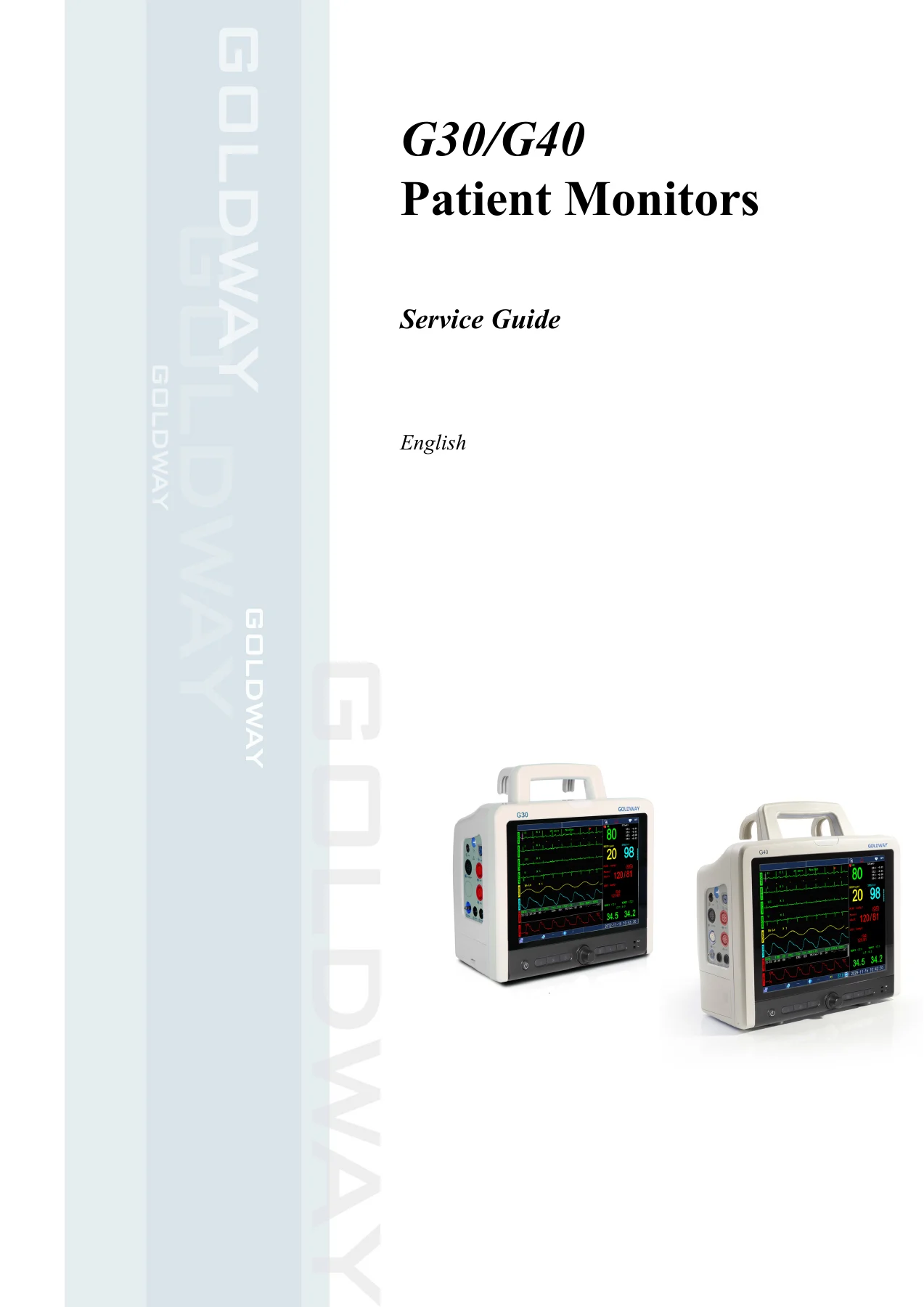
Philips Goldway G30 G40 Patient Monitor Service Guide - Edition 4 PDF — PDF page 1 preview
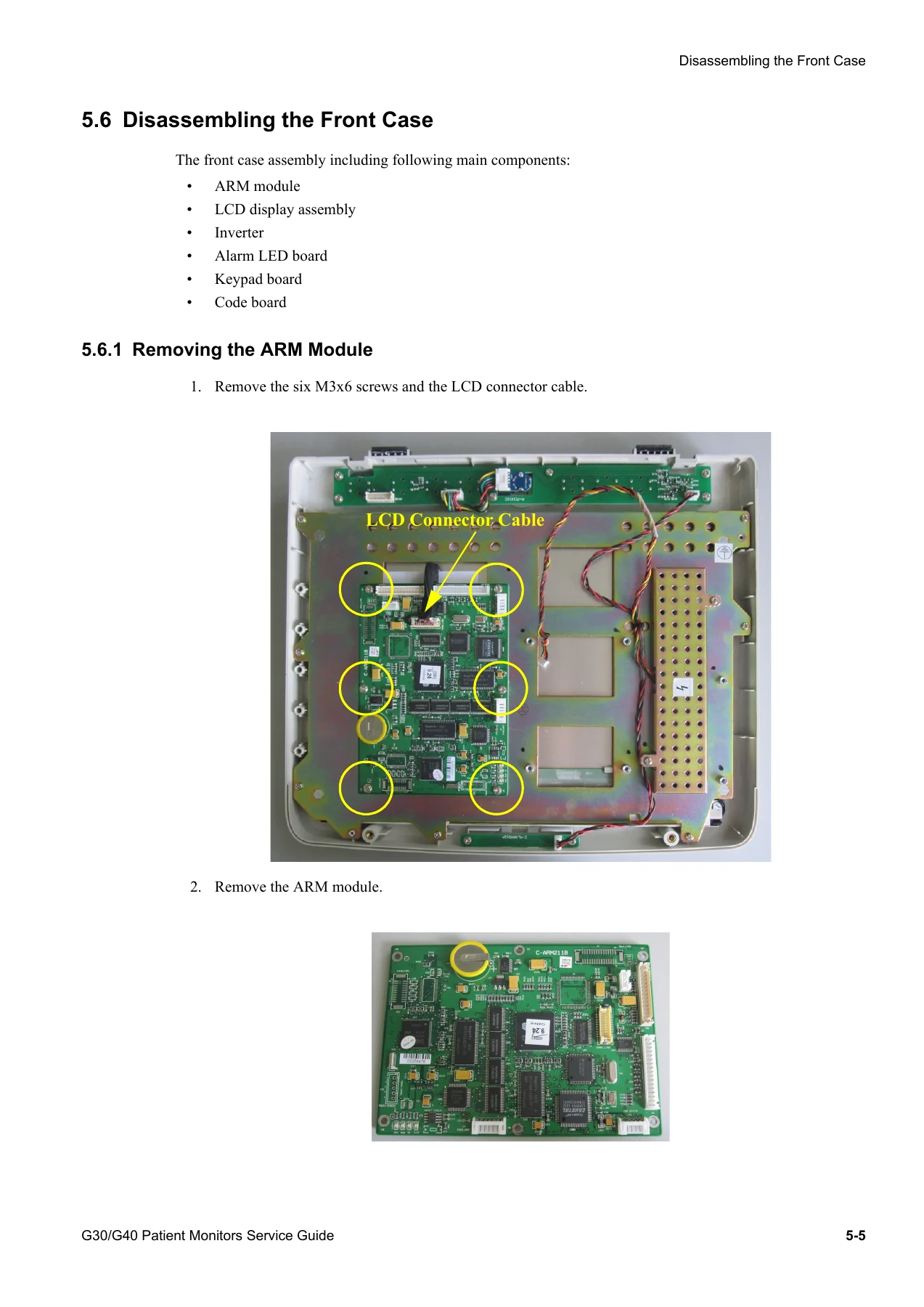
Philips Goldway G30 G40 Patient Monitor Service Guide - Edition 4 PDF — PDF page 57 preview
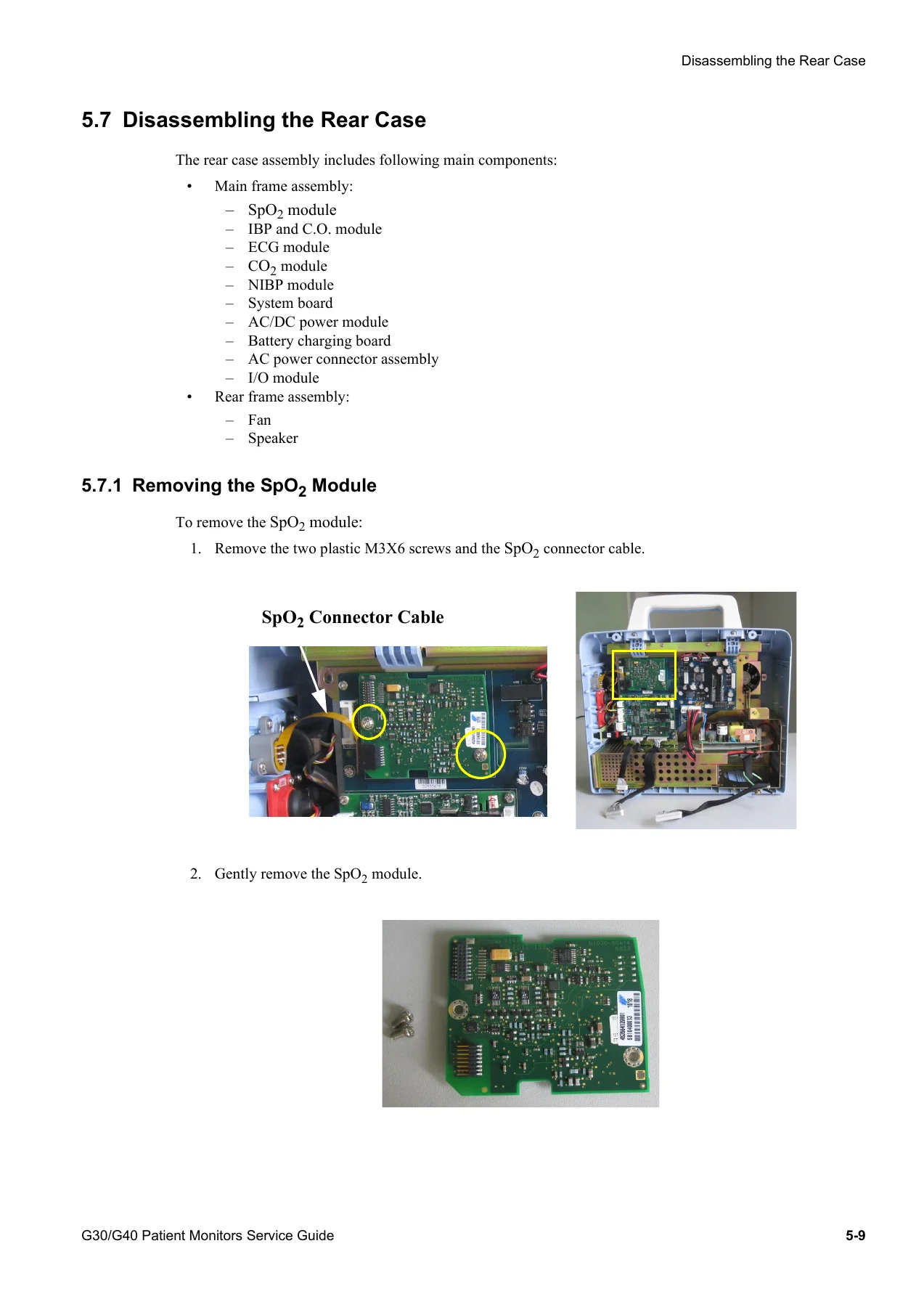
Philips Goldway G30 G40 Patient Monitor Service Guide - Edition 4 PDF — PDF page 61 preview

The Performance Verification and Electrical Safety Test sections walk through the exact procedures Philips Goldway requires after any installation, software upgrade, or internal repair — covering NIBP overpressure testing and calibration, Microstream CO2 calibration, IBP calibration, system enclosure leakage, protective earth continuity, and patient leakage current with mains voltage. The Troubleshooting chapter is organized by symptom (no ECG readings, unreliable SpO2, no CO2 readings, recorder faults, and more), pairing each symptom with a possible cause and the corrective action, frequently pointing straight to the relevant module-removal procedure.

Why Technicians Need This G30 G40 Patient Monitor Service Guide

This service guide gives biomedical engineering staff and independent service technicians the ability to diagnose whether a G30 or G40 fault is hardware or software, run manufacturer-specified safety and performance tests after any repair, and replace individual modules correctly using OEM screw sizes and disassembly sequences — all without guesswork. Working from the correct procedures and specifications in this Philips Goldway G30 G40 Patient Monitor Service Guide protects both patient safety and monitor warranty status, since Philips Goldway states that disassembly outside authorized procedures can invalidate coverage. This is an instant PDF download — there is no physical shipping or waiting. It downloads immediately after checkout, works on any computer, tablet, or phone, and can be printed or kept on a shop laptop for bench-side reference.


Reviews

There are no reviews yet.

Be the first to review “Philips Goldway G30 G40 Patient Monitor Service Guide – Edition 4 PDF”

What Our Customers Say

★★★★★ Live reviews from customers
Loading customer reviews...
0
    0
    Your Cart
    Your cart is emptyReturn to Shop
    🛒
    Recently Purchased
    🕒 verified order