★ TRUSTED BY 321,897+ PROFESSIONALS WORLDWIDE
🏒
Trusted Business
Verified & Licensed
πŸ›‘οΈ
Virus Free Files
100% Safe Downloads
πŸ”’
Secure Payment
SSL Protected
⚑
Instant Delivery
Available Immediately
Sale!

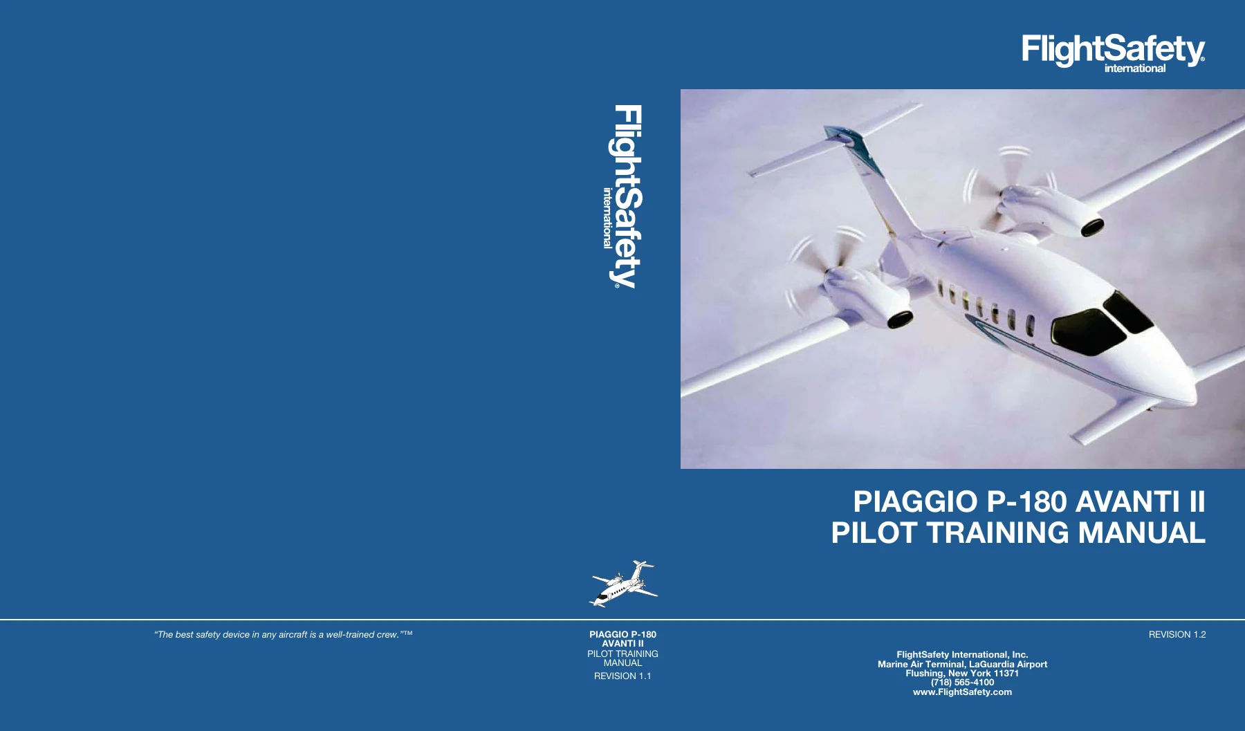
Piaggio P-180 Avanti II Pilot Training Manual – FlightSafety Systems & Procedures Guide

Original price was: $34.95.Current price is: $19.95.

Complete FlightSafety International pilot training manual for the Piaggio P-180 Avanti II. Covers all aircraft systems, normal and emergency procedures, performance, avionics, CRM/SRM, and walkaround. Instant PDF download.

⚑
Instant PDF Download
Available immediately
πŸ’Ύ
Save to Your Device
Download & keep forever
πŸ›‘οΈ
Antivirus Scanned
100% virus-free
🌍
Trusted Worldwide
175,000+ customers

Description

The Piaggio P-180 Avanti II Pilot Training Manual is a complete FlightSafety International training resource built for pilots who fly the Avanti II. This PDF edition covers every major aircraft system in detail β€” electrical, fuel, powerplant, hydraulics, landing gear, pressurization, ice protection, avionics, flight controls β€” along with normal and emergency procedures, performance data, weight and balance, and crew resource management. It is the same material used in FlightSafety’s West Palm Beach training program, presented in a structured chapter format that takes you from general aircraft description through to the most complex avionics subsystems.

File Details

  • Manual Type: Pilot Training Manual
  • Manufacturer: Piaggio
  • Model: P-180 Avanti II
  • Publisher: FlightSafety International
  • Language: English
  • Page Count: 745 pages
  • File Format: PDF
  • Revision: 1.2
  • Revision Date: April 2022
  • Original Date: August 2007
  • Training Location: West Palm Beach Learning Center, Florida

Chapters Covered

  • Chapter 1 – Aircraft General: Aerodynamic features (3LS, natural laminar flow, pusher-propeller, delta fins), composites, fuselage structure, flight compartment, passenger compartment, doors and windows, empennage, ground handling, servicing, publications
  • Chapter 2 – Electrical Power Systems: DC power system description, battery, generators, generator control units, ground power unit, distribution system, primary and secondary buses, bus switches, protection, overload sensors, emergency power
  • Chapter 3 – Lighting: Flight compartment lighting, dimming control, glareshield floodlights, displays, annunciator lights, passenger compartment lighting, cabin lights, reading and table lights, lavatory lights, baggage light, exterior lighting, landing/taxi lights, anticollision lights, navigation/position lights, wing inspection light
  • Chapter 4 – Master Warning System: Annunciator system, master WRN/CAUT buttons, aural warning system, test system, ground test/refuel panel, MFD flags, PFD flags, comparator flags, reversion flags
  • Chapter 5 – Fuel System: Storage system (fuselage, wing, collector, auxiliary tanks), vent system, drain system, indicating and control system, fuel panel, fuel quantity system, annunciators, flow indicators, ground test/refuel panel, boost pumps, firewall shutoff valve, crossfeed operation, refueling, defueling, limitations, additives
  • Chapter 7 – Powerplant: Engine ratings, engine stations, major components, compressor, combustion chamber, turbine, exhaust, accessory gearbox, reduction gearbox, compressor bleed valve, igniters, lubrication system, oil cooler, oil tank, fuel system, fuel control unit, engine power control, indicators, control levers, propeller system, primary governor, overspeed governor, beta and reverse control, fuel topping governor, feathering, autofeather, synchrophaser, limitations, emergency procedures
  • Chapter 8 – Fire Protection: Fire detection, detector, warning annunciators, testing circuit, fire extinguishing, fire bottle, ENG FIRE EXT pushbuttons, portable extinguisher, emergency procedures
  • Chapter 9 – Pneumatics: Normal manifold, precooler, shutoff valve, temperature sensors, check valve, flow control valve, emergency manifold, venturi, emergency shutoff valve, bleed-air control panel, bleed-air users, door seal inflation system, accumulator, emergency procedures
  • Chapter 10 – Ice and Rain Protection: Ice detection, engine intake boots, engine ice vane, oil cooler intake, inertial separation system, main wing anti-ice, forward wing anti-icing, windshield ice protection, pitot-static and AOA anti-ice, limitations, emergency procedures
  • Chapter 11 – Air Conditioning: ENVIRO system, components, distribution, operation, temperature control, freon air conditioner, limitations, emergency procedures
  • Chapter 12 – Pressurization: Description and components, auto controller, manual controller, outflow valves, vacuum regulator, vacuum jet pump, air filter, controls and indicators, operation, operational examples, limitations, emergency procedures
  • Chapter 13 – Hydraulic Power Systems: Main hydraulic system, components, operation, system checks, auxiliary hydraulic system, hydraulic pressurization, limitations, servicing, emergency procedures
  • Chapter 14 – Landing Gear and Brakes: Main gear, nose gear, squat switches, limit switches, weight-on-wheels functions, landing gear controls, aural warning, emergency landing gear system, steering system, brake system, emergency procedures
  • Chapter 15 – Flight Controls: Primary flight controls, ailerons, elevator, rudder, control wheels, secondary flight controls, aileron trim tab, rudder trim tab, horizontal stabilizer, flap control system, control lock, stall warning system, limitations, emergency procedures
  • Chapter 16 – Avionics: Collins Pro Line 21 system, flight environmental data, pitot-static system, air data system, electronic standby instrument system, RVSM, attitude and heading reference system, electronic flight instrument system, PFD/MFD operation, communications, navigation, hazard avoidance systems, weather radar, TCAS, TAWS, radio altimeter, flight management system, flight guidance system
  • Chapter 17 – Miscellaneous Systems: Oxygen system, components, operation, emergency locator transmitter, Techtest Type 503, UAB
  • Maneuvers and Procedures
  • Weight and Balance and Performance: Definitions, sample flight, weight and balance calculations, loading procedures, performance graphs, takeoff and landing performance, contaminated runways, Category II operations
  • Crew Resource Management (CRM) – Multi-Pilot: Situational awareness, command and leadership, communication process, decision making, altitude callouts
  • Single-Pilot Resource Management (SRM): Situational awareness, communication process, decision making
  • Walkaround: Exterior power-off preflight inspection with photographic guide
  • Appendix: Answers to chapter questions

That chapter list only hints at the depth. The Piaggio P-180 Avanti II Pilot Training Manual does not just describe what each system does β€” it explains how the system is put together, what happens when it fails, and what the pilot should see on the instruments. The electrical chapter walks through the prioritized bus architecture, the battery and generator control units, the ground power unit, and the emergency power unit with schematics that show power flow in normal, single-generator, and dual-generator-failure conditions. The powerplant chapter covers the PT6A-66/66B from the compressor air inlet through the reduction gearbox, including the fuel control unit, the propeller governor, beta and reverse control, autofeather, and the optional synchrophaser. The avionics chapter is effectively a Pro Line 21 operator’s guide β€” PFD and MFD formats, FMS operation, flight guidance modes, TCAS, TAWS, weather radar, and radio tuning. And the weight and balance section works through a complete sample flight so you can see exactly how the loading form, CG calculations, and performance charts are used together.

What This Training Manual Covers

The Piaggio P-180 Avanti II Pilot Training Manual is organized around the aircraft’s actual systems, not around a generic outline. Each chapter follows a consistent pattern: general description, component details, operating principles, normal indications, abnormal and emergency procedures, and limitations. That structure makes it equally useful for initial type training and for quick reference when something unexpected comes up in flight.

  • Electrical power β€” DC generation, battery, generator control units, bus distribution, emergency power unit, overload protection, and the prioritized bus system
  • Fuel β€” tank storage and venting, boost pumps, firewall shutoff valves, crossfeed operation, refueling and defueling, quantity indication, and fuel additives
  • Powerplant β€” PT6A-66/66B engine construction, lubrication, fuel control, torque and temperature indication, propeller governing, reversing, feathering, and autofeather
  • Hydraulics β€” main hydraulic power package, high-duty and low-duty modes, auxiliary hand pump, emergency gear extension, and brake system operation
  • Landing gear and brakes β€” main and nose gear, squat and limit switches, nosewheel steering, carbon brakes, parking brake, and emergency procedures
  • Pressurization β€” auto and manual controllers, outflow valves, vacuum jet pump, cabin altitude limiters, differential pressure relief, and emergency descent procedures
  • Ice and rain protection β€” ice detection, engine intake boots, inertial separators, main and forward wing anti-ice, windshield heat, and pitot-static/AOA heating
  • Avionics β€” Collins Pro Line 21, EFIS, air data and attitude heading systems, FMS, flight guidance, communications, navigation, TCAS, TAWS, and weather radar
  • Flight controls β€” primary and secondary controls, trim systems, flap control, stall warning, and gust lock
  • Master warning β€” annunciator panel, aural warnings, system test functions, and all PFD/MFD flags and comparator messages

Beyond systems, the manual includes a complete weight and balance and performance section with sample calculations and all the charts you need for flight planning. It also includes dedicated Crew Resource Management (CRM) and Single-Pilot Resource Management (SRM) chapters covering situational awareness, communication, decision making, and altitude callouts. A photographic walkaround section shows every item on the exterior preflight inspection.

An Important Note on This Manual

This is a training manual published by FlightSafety International. It is designed for familiarization and training purposes. The notice at the front of the manual states that it is based on information from the aircraft manufacturer’s pilot and maintenance manuals, and that where conflicts exist between this training manual and the manufacturer’s or FAA publications, the manufacturer’s or FAA publications take precedence. Pilots should always refer to the current FAA-approved Airplane Flight Manual (AFM) and the manufacturer’s maintenance manuals for operational and maintenance decisions. This training manual is an excellent systems-learning and reference resource, but it is not a substitute for the approved AFM or maintenance documentation.

Complete PDF Bookmark Tree

Complete Bookmarks

The complete bookmarks in the β€œPiaggio P-180 Avanti II Pilot Training Manual – FlightSafety Systems & Procedures Guide” are as follows:

Coverp. 1
LOEPp. 4
Contentsp. 5
CH01p. 6
TOCp. 6
INTRODUCTIONp. 10
GENERALp. 10
Aerodynamic Featuresp. 11
ompositesp. 12
Danger Areasp. 14
Engines/Propellersp. 15
Weight and Dimensionsp. 15
Fuel/Oil Capacityp. 17
FUSELAGEp. 17
Nose Sectionp. 17
Flight Compartmentp. 17
Passenger Compartmentp. 19
Aft Fuselagep. 19
Doors and Windowsp. 20
EMPENNAGEp. 27
Taxiing/Parking/Towingp. 28
Taxiingp. 28
Parkingp. 29
Towingp. 30
Placardsand Markingsp. 31
Exteriorp. 31
Interiorp. 31
Maintenance and Servicingp. 32
Preventive Maintenancep. 32
Servicingp. 32
Publicationsp. 33
AFMp. 33
ilots Operating Handbookp. 33
Airplane Weight And Balance Manualp. 33
QUESTIONSp. 34
LOFp. 8
1-1 P-180 Avanti IIp. 11
1-2 Composite Surfacesp. 13
1-3 Danger Areas (MAX PWR Position)p. 14
1-4 Engine/Propellerp. 15
1-5 Aircraft Dimensionsp. 16
1-6 Fuselagep. 17
1-7 Crew Storage Cabinetp. 17
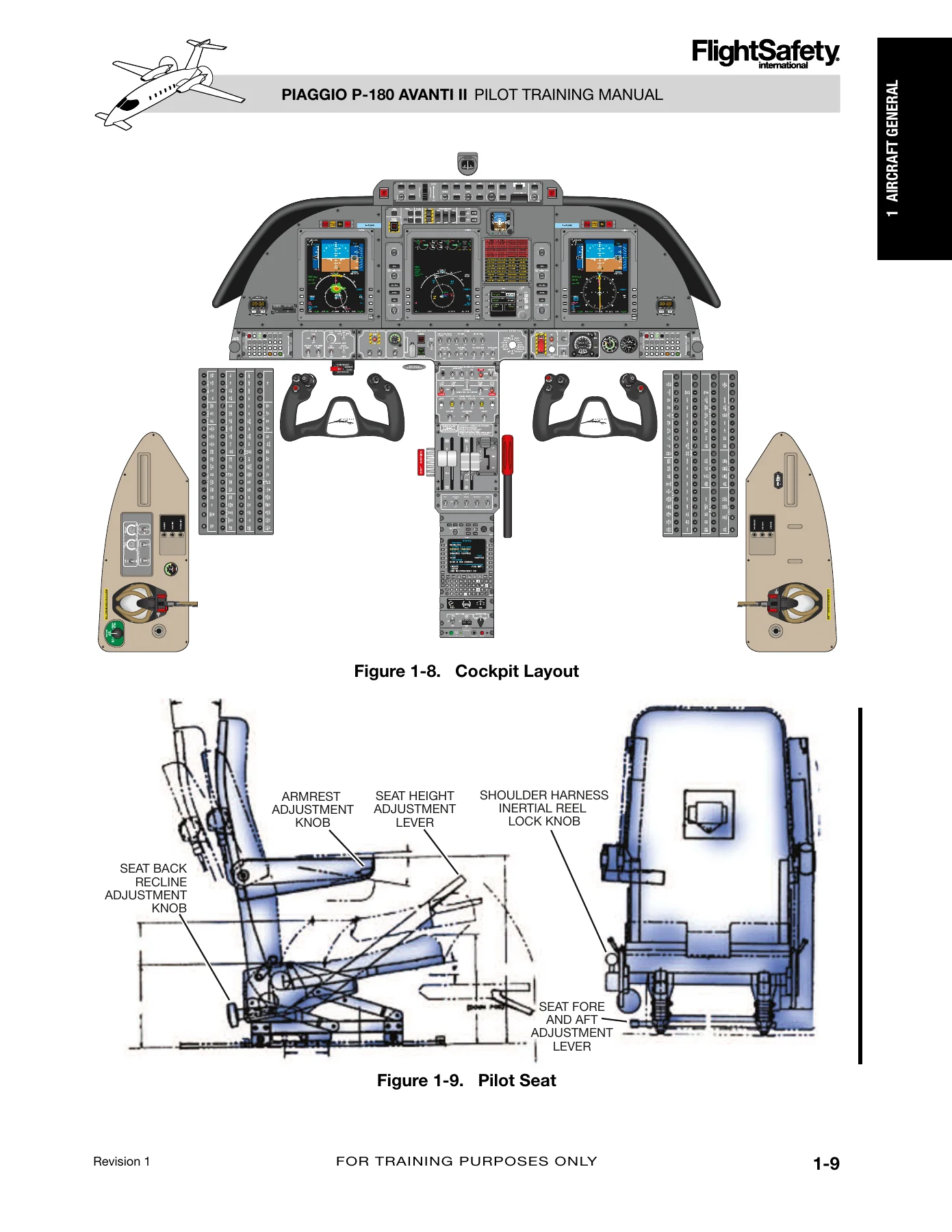
1-8 Cockpit Layoutp. 18
1-9 Pilot Seatp. 18
1-10 Passenger Compartmentp. 19
1-11 Lavatory Unitp. 19
1-12 Two Piece Cabin Doorp. 20
1-13 Upper Door Handlep. 20
1-14 Lower Doorp. 20
1-15 Inspection Windowsp. 21
1-16 Step 1 Openingβ€”Exteriorp. 21
1-17 Step 3 Openingβ€”Exteriorp. 21
1-18 Step 4 Openingβ€”Exteriorp. 22
1-19 Step 6 Openingβ€”Exteriorp. 22
1-20 Step 8 Openingβ€”Exteriorp. 22
1-21 Step 9 Openingβ€”Exteriorp. 22
1-22 Step 1 Closingβ€”Interiorp. 23
1-23 Step 3 Closingβ€”Interiorp. 23
1-24 Step 5 Closingβ€”Interiorp. 23
1-25 Step 5 Closingβ€”Interiorp. 23
1-26 Step 6 Closingβ€”Interiorp. 23
1-27 Step 6 Closingβ€”Interiorp. 23
1-28 Step 7 Closingβ€”Interiorp. 24
1-29 Step 8 Closingβ€”Interiorp. 24
1-30 Step 2 Openingβ€”Interiorp. 24
1-31 Step 2 Openingβ€”Interiorp. 24
1-32 Step 4 Openingβ€”Interiorp. 25
1-33 Step 9 Openingβ€”Interiorp. 25
1-34 Step 9 Openingβ€”Interiorp. 25
1-35 Step 7 Closingβ€”Exteriorp. 26
1-36 Baggage Doorp. 26
1-37 Emergency Exit/Windowp. 26
1-38 Rudder and Vertical Stabilizerp. 27
1-39 Turning Anglep. 28
1-40 Aircraft Plugs and Coversp. 29
1-41 Towing Turning Anglep. 30
1-42 Steering Disconnect Pinp. 31
LOTp. 9
1-1 Aircraft Weightsp. 15
1-2 Cabin and Entry dimensionsp. 19
1-3 Baggage Compartmentp. 19
CH02p. 36
TOCp. 36
INTRODUCTIONp. 40
GENERALp. 40
DC POWER SYSTEM DESCRIPTIONp. 41
Master Switchesp. 41
MFD System Pagep. 42
Batteryp. 43
Generatorsp. 46
Generator Control Unitsp. 47
Ground Power Unit (GPU)p. 49
Distribution Systemp. 49
BUS Switchesp. 55
Protectionp. 57
Operationp. 66
Normalp. 66
Abnormal/Emergencyp. 68
AC POWER SYSTEM Descriptionp. 70
EMERGENCY POWERp. 71
Descriptionp. 71
LIMITATIONSp. 72
Batteryp. 72
Starter-Generatorp. 72
Ground Power Unitp. 72
Cabin Electrical Powerp. 72
QUESTIONSp. 74
LOFp. 39
2-1 Master Switches Panelp. 41
2-2 MFD System Page and EIS Displayp. 42
2-3 Batteryp. 43
2-4 Battery Malfunction Annunciatorsp. 43
2-5 Battery Power on Ground Bus Disconnect Switch Normalp. 44
2-6 Battery Voltage Startp. 45
2-7 Battery/ANN Testp. 46
2-8 Generatorsp. 46
2-9 LH GCU and RH GCUp. 47
2-10 GCUβ€”START Switchesp. 48
2-11 GPU Connectionp. 49
2-12 Schematic Legendp. 50
2-13 Electrical Schematic Overviewp. 50
2-14 Primary Busesp. 51
2-15 Secondary Busesp. 53
2-16 COM 1 ONLY Positionp. 55
2-17 ON Positionp. 56
2-18 NORM Position on Groundp. 57
2-19 BUS DISC Position on Groundp. 58
2-20 BUS DISC Position on Gropundp. 59
2-21 EMER Position Flight or Ground (Battery Power Only)p. 60
2-22 Overview of EMER Position Flight or Ground (Battery Power Only)p. 60
2-23 Normal Overload Sensor Positionp. 61
2-24 Left Overload Sensor Trippedp. 62
2-25 Pilot and Copilot Circuit-Breaker Panelsp. 63
2-26 Main Junction Boxp. 65
2-27 Rear Vanity Closetp. 65
2-28 GPU Startp. 66
2-29 Normal Operationp. 67
2-30 Single Generator Operatingp. 68
2-31 Dual Generator Failure Annunciationp. 69
2-32 Dual Generator Failure in Flight (BUS DISC in EMER Position)p. 70
2-33 Emergency Powerp. 71
2-34 EPU Operation-Essential Bus Poweredp. 71
2-35 EPU Operation-Essential Bus Unpoweredp. 71
LOTp. 39
2-1 DC Electrical Load Distributionp. 54
CH03p. 76
TOCp. 76
INTRODUCTIONp. 80
GENERALp. 80
FLIGHT COMPARTMENTp. 81
Map Lightsp. 81
Dimming Control Panelp. 82
PASSENGER COMPARTMENTp. 87
General Lightingp. 88
Reading and Table Lightsp. 88
Passenger Advisory Lightsp. 89
Lavatory Lightsp. 89
BAGGAGE COMPARTMENTp. 90
EXTERIOR LIGHTINGp. 90
Landing Lightsp. 91
Taxi Lightp. 92
Anticollision Lightsp. 92
Ground Beacon Lightp. 93
Recognition Lightp. 93
Navigation/Position Lightsp. 93
Wing Inspection Lightp. 94
ABNORMALSp. 94
LOFp. 78
3-1 Flight Compartment Lightingp. 81
3-2 Copilot Map Lightp. 81
3-3 LIGHT DIMMING CONTROL Panelp. 82
3-4 Glareshield Lightingp. 82
3-5 Display Lightsp. 84
3-6 Electroluminescent and Incandescent Panelsp. 85
3-7 Cockpit Lightsp. 86
3-8 LAMP Switchp. 86
3-9 Cockpit Light Control Switchp. 86
3-10 Annunciator Lightsp. 86
3-11 Passenger Compartmentp. 87
3-12 Cabin Overhead Lightsp. 88
3-13 Entry Light and Switchp. 88
3-14 Reading Lightp. 88
3-15 Table Lightp. 88
3-16 NO SMOKING/FASTEN SEAT BELT Signp. 89
3-17 Lavatory Compartment Lights Locationsp. 89
3-18 Lavatory Light Controlp. 90
3-19 Baggage Compartment Light and Switchp. 90
3-20 Lights Panelp. 91
3-21 Landing Lightsp. 91
3-22 Landing-Taxi Lights MFD Displayp. 91
3-23 Taxi Lightsp. 92
3-24 Top Anticollision Lightp. 92
3-25 Bottom Anticollision Lightp. 93
3-26 Ground Beacon Lightp. 93
3-27 Recognition Lightp. 93
3-28 Navigation Lightp. 93
3-29 Position Lightp. 94
3-30 Wing Inspection Lightp. 94
LOTp. 79
3-1 Light and Controlsp. 83
CH04p. 98
TOCp. 98
INTRODUCTIONp. 102
ANNUNCIATOR SYSTEMp. 102
Master WRN and CAUT Buttonsp. 103
AURAL WARNING SYSTEMp. 105
TEST SYSTEMp. 106
Ground Test/Refuel Panelp. 107
Visual Annunciationsp. 108
Multifunctional Display (MFD) FLAGSp. 108
Primary Flight Display (PFD) FLAGSp. 112
QUESTIONSp. 124
LOFp. 100
4-1 Master WRN/CAUT Buttonsp. 103
4-2 SYS TEST Knobp. 106
4-3 Ground Test/Refuel Panelp. 107
4-4 MFD Flagsβ€”Visual Annunciationsp. 108
4-5 MFD Comparator Flagsp. 111
4-6 PFD Flagsβ€”Visual Annunciationsp. 112
4-7 PFD Comparator Flagsp. 118
4-8 PFD No-Comparator Flagsp. 121
4-9 PFD Reversion Flagsp. 122
LOTp. 100
4-1 Annunciatorsp. 103
4-2 Ground Test Lightsp. 108
4-3 MFD Flagsβ€”Visual Annunciationsp. 109
4-4 MFD Comparator Flagsβ€”Visual Annunciationsp. 111
4-5 PFD Flagsβ€”Visual Annunciationsp. 113
4-6 PFD Yellow Comparator Flagsp. 119
4-7 PFD No-Comparator Flagsp. 121
4-8 PFD Reversion Flagsp. 122
CH05p. 126
TOCp. 126
Introductionp. 130
Generalp. 130
STORAGE SYSTEM DESCRIPTIONp. 131
Fuselage Tankp. 131
Wing Tankp. 132
Collector Tankp. 133
Auxiliary Tankp. 133
Fuel Vent Systemp. 134
Fuel Drain Systemp. 135
INDICATING AND CONTROL SYSTEMp. 136
Fuel Panelp. 136
Annunciatorsp. 137
Flow Indicatorsp. 137
Ground Test/Refuel Panel (GTRP)p. 138
FUEL SYSTEM OPERATIONp. 139
Boost Pumpsp. 139
Firewall Shutoff Valvep. 141
Crossfeed Operationp. 142
REFUELINGp. 143
Gravity Refuelingp. 143
Pressure Refueling (SPR)p. 144
efuelingp. 146
Abnormal Operationsp. 146
LIMITATIONSp. 148
Allowable Fuelp. 148
ADDITIVESp. 148
QUESTIONSp. 150
LOFp. 128
5-1 Fuel Storage Tanks Locationp. 131
5-2 Fuel Storage Tanksp. 132
5-3 LH Auxiliary Tankp. 133
5-4 Fuel Vent Systemp. 134
5-5 Collector Tank Sumpp. 135
5-6 Engine Fuel Filter Drainp. 135
5-7 Wing Vent Drainingp. 135
5-8 Fuel Control Panelp. 136
5-9 Ground Test/Refuel Panelp. 138
5-10 Normal Operation (Larger Fuel System Shown)p. 140
5-11 RH Fuel Firewall Valvep. 141
5-12 Fuel Filterp. 142
5-13 Crossflow Operationsp. 142
5-14 Gravity Refuelingp. 143
5-15 Pressure Refuelingp. 144
5-16 SPR Adapterp. 145
5-17 Defuelingp. 146
5-18 Fuel Pump Failurep. 147
LOTp. 128
5-2 Annunciatorsp. 137
5-1 Tank Capacityp. 132
CH06p. 152
CH07p. 154
TOCp. 154
Introductionp. 160
Generalp. 160
Engine Ratingsp. 160
Engine Stationsp. 161
Engine Termsp. 161
Powerplantp. 161
General Principlesp. 163
Major Engine Componentsp. 164
Ignitersp. 172
Engine Lubrication Systemp. 173
Engine Fuel Systemp. 178
Engine Instrumentsp. 186
Control Leversp. 188
Control Levers Operationp. 191
Propellerp. 191
Blade Anglep. 195
Primary Governorp. 195
Overspeed Governorp. 201
Beta and Reverse Controlp. 203
Fuel Topping Governorp. 206
Propeller Featheringp. 206
Autofeather Systemp. 207
Synchrophaser (Optional)p. 211
Limitationsp. 213
Power Handling at Altitudep. 213
Starter Limitationsp. 213
Temperaturep. 213
Oil Pressureand Temperaturep. 215
Engine Torque Limitsp. 215
Engine ITT Limitsp. 216
Emergency Proceduresp. 216
Identifying Dead Enginep. 216
Engine Securingp. 217
Low Oil Pressurep. 217
High Oil Pressurep. 217
High Oil Temperaturep. 217
Overspeed Propellerp. 217
QUESTIONSp. 218
LOFp. 156
7-1 PT6A-66/66B Enginep. 162
7-2 Engine Cross Sectionp. 163
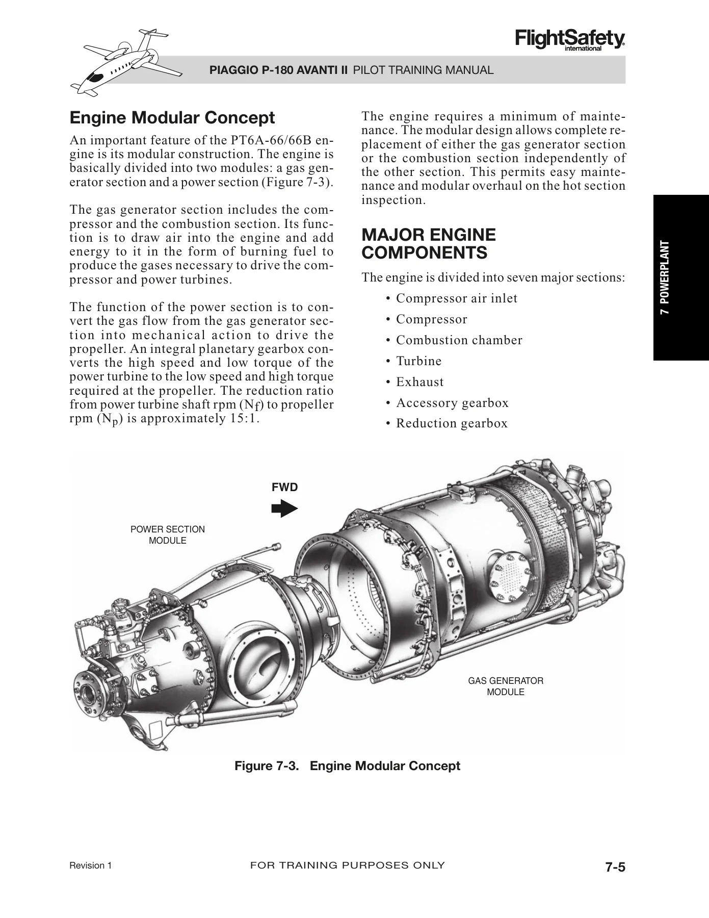
7-3 Engine Modular Conceptp. 164
7-4 Compressor Air Inletp. 165
7-5 Compressor Air Inlet Casep. 165
7-6 Compressor Sectionp. 166
7-7 Combustion Chamberp. 166
7-8 Combustion Sectionp. 166
7-9 Power Turbinesp. 167
7-10 Exhaust Sectionp. 168
7-11 Accessory Gearboxp. 169
7-12 Front and Rear Accessory Drivesp. 170
7-13 Reduction Gearboxp. 171
7-14 Compressor Bleed Valvep. 172
7-15 Igniter Switchesp. 172
7-16 Ignition Systemp. 173
7-17 Engine Lubrication Systemp. 174
7-18 Oil Coolerp. 175
7-19 Oil Cooler Inlet and Outlet Ductsp. 175
7-20 Outlet Ductsp. 176
7-21 Oil Tank Cutawayp. 176
7-22 Oil Dipstickp. 177
7-23 Magnetic Chip Detectorp. 178
7-24 LH Engine Fuel Control Systemp. 179
7-25 Oil-to-Fuel Heat Exchangerp. 180
7-26 Dual Fuel Manifoldp. 181
7-27 Duplex Fuel Nozzlesp. 181
7-28 Flow Divider and Purge Valvesp. 182
7-29 Simplified Fuel Control Systemp. 184
7-30 3D Cam and Fuel Valvep. 185
7-31 Engine Display and Indicationsp. 187
7-32 Cockpit Control Leversp. 188
7-33 Power Managementp. 189
7-34 Power Leversp. 189
7-35 Condition Leversp. 190
7-36 Propeller Systemp. 192
7-37 Hartzell Propellersp. 193
7-38 Blade Anglesp. 194
7-39 Propeller Governorp. 195
7-40 Propeller Governor Diagramp. 196
7-41 Propeller Onspeedp. 197
7-42 Propeller Overspeedp. 197
7-43 Propeller Underspeedp. 198
7-44 Mechanical Linkage of Propellerp. 200
7-45 Beta Rodsp. 200
7-46 Overspeed Governorp. 201
7-47 Overspeed Governor Activationp. 202
7-48 PROP OVSP Switchp. 202
7-49 Beta Linkagep. 203
7-50 Entering Reversep. 204
7-51 Exiting Reversep. 205
7-52 Propeller Featheringp. 206
7-53 Autofeather Solenoid Valvep. 207
7-54 AUTOFEATHER Systemp. 207
7-55 AUTOFEATHER ARM Switchp. 208
7-56 MFD Display with AFX Lightsp. 208
7-57 Autofeather in ARM Position (R Engine Failed)p. 209
7-58 Autofeather Switch in TEST Positionp. 210
7-59 Woodward Type II Fixed Phase Synchrophaser Systemp. 211
7-60 Synchrophaser Control Boxp. 212
7-61 SYNCPH Schematicp. 212
7-62 SYNCPH Switchp. 213
7-63 Engine Torque Limitsp. 215
7-64 Engine ITT Limitsp. 216
LOTp. 158
7-1 Engine Operating Limitsp. 214
CH08p. 222
TOCp. 222
Introductionp. 226
FIRE DETECTIONp. 226
Detectorp. 227
Warning Annunciatorsp. 227
Operationp. 227
Testing Circuitp. 229
FIRE EXTINGUISHINGp. 230
Fire Bottlep. 231
ENG FIRE EXT Pushbuttonsp. 233
Operationp. 233
Portable Extinguisherp. 234
EMERGENCY PROCEDURESp. 235
Engine Fire on Groundp. 235
Engine Fire in Flightp. 235
QUESTIONSp. 236
LOFp. 224
8-1 Fire Detection Loopp. 227
8-2 Fire Annunciatorsp. 227
8-3 Fire Detection Systemp. 228
8-4 Fire Detector Operating Principlep. 229
8-5 SYS TEST Selectorβ€”FIRE DETp. 230
8-6 Fire Extinguishing Systemp. 230
8-7 Fire Bottlep. 231
8-8 Bottle Pressure Gagep. 232
8-9 Acceptable Operating Zonep. 232
8-10 ENG FIRE EXT Pushbuttonp. 233
8-11 Right Engine Fire Detectedp. 233
8-12 Accessory Gearbox Sectionp. 234
8-13 Engine Hot Sectionp. 234
8-14 Portable Fire Extinguisherp. 234
8-15 Pressure Gagep. 234
CH09p. 238
TOCp. 238
Introductionp. 242
Generalp. 242
Normal Manifold Componentsp. 244
Emergency Manifold Componentsp. 246
Emergency Shutoff Valve (SOV)p. 246
BLEED-AIR Control Panelp. 247
Bleed-Air Usersp. 248
Operationp. 249
Door Seal Inflation Systemp. 250
Accumulatorp. 251
Operationp. 252
Emergency Proceduresp. 252
DOOR SEAL Annunciator Illuminatedp. 252
BLEED TEMP Annunciator Illuminatedp. 253
Questionsp. 254
LOFp. 240
9-1 Pnuematic Systemp. 243
9-2 Normal Manifoldp. 244
9-3 Precoolerp. 245
9-4 Emergency Manifoldp. 246
9-5 Venturip. 247
9-6 BLEED-AIR Panelp. 247
9-7 Emergency Shutoff Valve Openp. 248
9-8 Door Sealp. 250
9-9 Door Seal Systemp. 251
9-10 Accumulatorp. 251
9-11 Door Sealp. 252
9-12 BLEED TEMP Annunciator Illuminatedp. 253
CH10p. 256
TOCp. 256
Introductionp. 260
Generalp. 260
Ice Detectionp. 261
Operationp. 262
Engine Intake Bootsp. 263
Generalp. 263
Componentsp. 264
Operationp. 265
Engine Ice Vane/Oil Cooler Intakep. 267
Inertial Seperation Systemp. 267
Oil Cooler Intake Systemp. 269
Main Wing Anti-ice Systemp. 270
Componentsp. 270
Operationp. 273
Forward Wing Anti-icing Systemp. 274
Componentsp. 274
Operationp. 275
Windshield Ice Protection Systemp. 276
Selector Switchesp. 277
Operationp. 278
Checking System Operationp. 278
Pitot Static and AOA Anti-ice Systemp. 279
Limitationsp. 281
Emergency Proceduresp. 281
Flashing Ice Lightp. 281
ICE Light Odd or Always Onp. 281
Boots Deice Light Off or Always Onp. 282
Questionsp. 284
LOFp. 258
10-1 Ice Detector Block Diagramp. 261
10-2 Ice Detectorp. 262
10-3 Visual Accretion Probep. 262
10-4 ICE Lightp. 262
10-5 ICE DETp. 263
10-6 Wing Inspection Lightp. 263
10-7 Deicing Bootp. 264
0-8 ANTI-ICE Panelp. 265
10-9 Engine Intake Boot Deice Systemp. 266
10-10 Engine Inlet Bypass Ductp. 267
10-11 Inertial Separation Systemp. 267
10-12 Separating Modep. 268
10-13 Engine Intake Anti-Ice Vane System Lightsp. 268
10-14 Oil Cooler Intake Systemp. 269
10-15 Main Wing Anti-Ice Systemp. 271
10-16 Wingtip Slitsp. 273
10-17 Forward Wingp. 274
10-18 Forward Wing Anti-Ice Systemp. 275
10-19 Windshieldp. 276
10-20 Windshield Ice Protection Systemp. 277
10-21 AOA Vane, Pitot Tubes, and TAT Probep. 279
10-22 Pitot-Static Systemp. 280
10-23 Left and Right Pitot Lightsp. 280
LOTp. 259
10-1 Windshield Zonesp. 277
CH11p. 286
TOCp. 286
Introductionp. 290
Generalp. 290
ENVIRO Systemp. 291
Componentsp. 291
Distributionp. 296
Operationp. 299
Temperature Controlp. 299
Temperature Control Operationp. 300
Emergency Operationp. 300
Electrical Powerp. 301
Freon Air Conditionerp. 301
General Descriptionp. 301
Control and Operationp. 302
Electrical Powerp. 302
Limitationsp. 303
Emergency Proceduresp. 303
Emergency Operationp. 303
Environmental Smoke in Cockpitp. 303
DUCT TEMP Annunciator illuminatedp. 303
QUESTIONSp. 304
LOFp. 288
11-1 ENVIRONMENTAL Control Panelp. 291
11-2 Precoolerp. 291
11-3 ENVIRO System FCVp. 292
11-4 Ground Blower Fanp. 292
11-5 ENVIRO Heat Exchangerp. 292
11-6 Acoustical Mufflersp. 293
11-7 Heating System Schematicp. 294
11-8 Optional Third Evaporatorp. 295
11-9 Air Distribution System Schematicp. 297
11-10 Temperature Controllersp. 296
11-11 Cabin Overhead Adjustable Outletp. 298
11-12 Cockpit Adjustable Outletsp. 298
11-13 Cockpit Blowerp. 298
11-14 Freon Air Conditionerp. 301
11-15 Cabin Evaporatorp. 301
11-16 Cabin Outletp. 301
11-17 COOLING Control Panelp. 302
CH12p. 306
TOCp. 306
Introductionp. 310
Generalp. 310
DESCRIPTION AND COMPONENTSp. 311
AUTO CONTROLLERp. 312
MANUAL CONTROLLERp. 313
OUTFLOW VALVESp. 313
VACUUM REGULATORp. 316
VACUUM JET PUMPp. 316
AIR FILTERp. 317
ADDITIONAL CONTROLS AND INDICATORSp. 317
OPERATIONp. 320
AUTOMATICp. 320
MANUALp. 321
CABIN DUMPINGp. 322
OPERATIONAL EXAMPLESp. 322
AUTOMATIC SCHEDULE LOGICp. 322
CABIN SELECT LOGICp. 326
LIMITATIONSp. 330
EMERGENCY PROCEDURESp. 333
EMERGENCY DESCENTp. 333
RAPID OR EXPLOSIVE DECOMPRESSIONp. 333
Cabin Altitude above 9,500 Feetp. 334
Cabin Differential Pressure above 9.4 psidp. 334
Cabin Depressurization (Dump) Procedurep. 334
CABIN PRESS Auto Mode Failurep. 334
QUESTIONSp. 336
LOFp. 308
12-1 Pressurization Systemp. 311
12-2 CABIN PRESS Panelp. 312
12-3 Primary Outflow Valvep. 313
12-4 Secondary Outflow Valvep. 313
12-5 Base Assemblies and Coversp. 313
12-6 Primary Outflow Valve Componentsp. 314
12-7 Secondary Outflow Valve Componentsp. 315
12-8 Air Filterp. 317
12-9 Cabin Pressure Selectorp. 317
12-11 CAB SEL/AUTO SCHED Switchp. 318
12-10 AUTO/MAN Switchp. 318
12-12 DUMP Switchp. 318
12-13 Pressurization System in Emergencyp. 319
12-15 Cabin Rate of Climb Gaugep. 320
12-14 Cabin Altitude/Differential Pressure Gaugep. 320
12-16 Automatic Schedule Logicβ€”Flight Originates and Terminates at Same Elevationp. 323
12-17 Automatic Schedule Logicβ€”Landing Field Altitude above Schedule and Takeoffp. 325
12-18 Automatic Schedule Logicβ€”Return Flight Profile (Takeoff at 5,600 Feet)p. 327
12-19 Cabin Select Logicβ€”Takeoff and Landing Field at 100 Feetp. 328
12-20 Cabin Select Logicβ€”Takeoff at 100 Feet and Landing at 5,600 Feetp. 329
12-21 Cabin Select Logicβ€”Takeoff at 5,600 Feet and Landing at 100 Feetp. 331
12-22 Cabin Select Logicβ€”Required Reselection Prior to Climbingp. 332
LOTp. 309
12-1 Protections and Warningsp. 333
12-2 Time of Useful Consciousnessp. 333
CH13p. 338
TOCp. 338
Introductionp. 342
Generalp. 342
Main Hydraulic Systemp. 342
Componentsp. 343
Operationp. 347
Hydraulic System Checksp. 347
Auxiliary Hydraulic Systemp. 350
Hydraulic Pressurizationp. 350
Limitationsp. 351
Servicingp. 351
Replenishing Fluidp. 351
Emergency Proceduresp. 351
Complete Hydraulic System Failurep. 353
Questionsp. 354
LOFp. 340
13-1 Hydraulic Packagep. 343
13-2 Hydraulic Package-Cutaway Viewp. 343
13-3 DC Electric Motorp. 344
13-4 Electronic Pressure Control Unitp. 344
13-5 Optical Level Sensorp. 345
13-6 Filter Assemblyp. 346
13-7 HYD Switchp. 346
13-8 Hydraulic Systemp. 348
13-9 SYS TEST Rotary knobp. 349
13-10 Ground Test/Refuel Panelp. 349
13-11 Hand Pumpp. 350
13-12 EMERG LDG T-Handlep. 350
13-13 Fluid Filler Portp. 351
13-14 HYD PRESS Annuciatorp. 351
13-15 Hydraulic System Lossp. 352
CH14p. 356
TOCp. 356
Introductionp. 360
Landing Gearp. 360
Main Gearp. 361
Nose Gearp. 361
Squat Switchesp. 361
Limit Switchesp. 362
Landing Gear Weight-On-Wheelsβ€”Systems Functionp. 362
Landing Gear Controlsp. 363
Aural Warningp. 364
Emergency Landing Gear Systemp. 366
Operationp. 367
Limitationsp. 367
Emergency Proceduresp. 367
Steering Systemp. 371
Componentsp. 371
Operationp. 374
Limitationsp. 374
Emergency Proceduresp. 374
Brake Systemp. 376
Componentsp. 376
Operationp. 379
Questionsp. 384
LOFp. 358
14-1 Main Landing Gearp. 361
14-2 Nose Landing Gearp. 361
14-3 Main Gear Squat Switchp. 362
14-4 Up and Down Limit Switchesp. 362
14-5 Landing Gear Panelp. 363
14-6 Gear Mute Switchp. 364
14-7 Audio Warningp. 365
14-8 EMERG LDG T-Handlep. 366
14-9 Landing Gear Systemβ€”Normal Operationβ€”Gear Extendedp. 368
14-10 Landing Gear Systemβ€”Emergency Operationp. 369
14-11 Steering Manifoldp. 371
14-12 Command Potentiometerp. 372
14-13 Feedback Potentiometerp. 372
14-14 Steering Control Buttonp. 373
14-15 Steer T-O/Steer Taxi Lightp. 373
14-16 Nosewheel Steering Systemp. 375
14-17 Brake Assemblyp. 376
14-18 Relief Valvesp. 377
14-19 Three-Way Selector Valvep. 378
14-20 Brake Wearp. 378
14-21 Brake Wear Indicatorsp. 378
14-22 Parking Brake Systemβ€”Normal Operationp. 380
14-23 Wheel and Brake Systemβ€”Normal Operationp. 381
14-24 Brake Systemβ€”Emergency Operationp. 382
CH15p. 386
TOCp. 386
INTRODUCTIONp. 390
GENERALp. 390
PRIMARY FLIGHT CONTROLSp. 391
AILERONSp. 391
ELEVATORp. 392
RUDDERp. 392
CONTROL WHEELSp. 392
SECONDARY FLIGHT CONTROLSp. 393
AILERON TRIM TABp. 393
RUDDER TRIM TABp. 394
HORIZONTAL STABILIZERp. 395
FLAP CONTROL SYSTEMp. 398
MAIN WING FLAPSp. 399
ELECTRONIC CONTROL UNITp. 402
FLAP OPERATIONp. 405
CHECKS AND TESTSp. 407
CONTROL LOCKp. 407
STALL WARNING SYSTEMp. 409
ANGLE-OF-ATTACK PROBEp. 409
STALL WARNING COMPUTERp. 410
ABNORMAL INDICATIONp. 410
SYSTEM TESTp. 410
Limitationsp. 411
Airspeed Limitationsp. 412
Airspeed Indication Markingsp. 412
Emergency Proceduresp. 412
Longitudinal Trim RunAway (Pitch Trim Runaway)p. 412
Primary Longitudinal Trim Failure (PRI PITCH TRIM Failure)p. 412
Longitudinal Control Spring Failurep. 412
Flap System Malfunctionp. 413
QUESTIONSp. 414
LOFp. 388
15-1. Flight Controlsp. 391
15-2. Aileronsp. 391
15-3. Elevatorp. 392
15-4. Rudderp. 392
15-5. Pilot and Copilot ControlWheelsp. 393
15-6. Aileron Trim Tabp. 393
15-7. Control Wheel Trim Switchp. 394
15-8. TRIM Indicatorsp. 394
15-9. Rudder Trim Tabp. 394
15-10. Horizontal Stabilizerp. 395
15-11. Horizontal Pitch TrimActuatorp. 395
15-12. Up-Down Springp. 396
15-13. Horizontal Stabilizer Travel Limitsβ€”Schematicp. 396
15-14. Three-Motor Screwjack Actuatorp. 397
15-15. PITCH TRIM Switchp. 397
15-16. Pitch Index Markingsp. 398
15-17. Flap Systemp. 399
15-18. Single-Slotted Inboard Flapp. 400
15-19. Outboard Fowler Flapp. 400
15-20. Single-Slotted Forward Wing Flapp. 400
15-21. Forward Wing Flap Actuatorp. 401
15-22. Electronic Control Unitp. 402
15-23. Flap Control Leverp. 402
15-24 MFD and PFDβ€”FLAPS Position Indicationp. 404
15-25 Flaps Deployment/Retraction Schedulep. 405
15-26 Audio Warningp. 406
15-27 Gust Lockp. 408
15-28 Gust Lock Installationp. 408
15-29 Control Column Connecting Rodp. 408
15-30 STALL Warning Lightp. 409
15-31 AOA Probep. 409
15-32 Low Speed Cue Indicationp. 411
LOTp. 389
15-1 Pitch Trim Motorsp. 397
15-2 Flap Settingp. 402
CH16p. 423
TOCp. 416
Introductionp. 424
The Collins Pro Line 21 Systemp. 424
Generalp. 424
Operationp. 425
IAPSp. 428
Maintenance Diagnotic Computerp. 428
Avionics Bay Cooling Systemp. 428
General Avionics System Limitationsp. 429
Flight Environmental Datap. 436
Pitot-Static Systemp. 436
Air Data Systemp. 439
Standby Instrument Systemp. 441
RVSMp. 445
Limitationsp. 445
Emergency Proceduresp. 446
Attitude and Heading Reference Systemp. 448
Generalp. 448
Componentsp. 448
Operationsp. 449
Magnetic Compassp. 452
Limitationsp. 452
Emergency Proceduresp. 453
Electronic Flight Instrument Systemp. 454
Generalp. 454
PFD Operationp. 455
Display Control Panel Operationp. 465
MFD Operationp. 470
Engine Indicating System (EIS)p. 474
MFD System Pagep. 478
Cursor Control Panel Operationp. 482
Reversionary Panel Operationp. 485
EFIS Limitationsp. 487
EFIS Emergency Proceduresp. 487
Communicationsp. 489
Generalp. 489
VHF Communicationsp. 489
Radio Tuning Unitp. 491
Control Display Unitp. 494
Audio Systemp. 498
HF Communication Systemp. 501
SAT COM Systemp. 502
Static Wicksp. 503
Cockpit Voice Recordersp. 504
Communication System Limitationsp. 506
Emergency Proceduresp. 506
Navigationp. 507
Generalp. 507
VOR/ILS/MLR Systemp. 507
DME Systemp. 508
ADF Systemp. 512
ATC Transponder Systemp. 516
Navigation Systems Limitationsp. 520
Emergency Proceduresp. 520
Hazard Avoidance Systemsp. 521
Generalp. 521
Weather Radarp. 521
TCASp. 528
Displays and Traffic Symbolsp. 535
Questionsp. 608
LOFp. 420
16-1 Pro Line 21 Overall System Schematicp. 426
16-2 Cockpit Layoutp. 434
16-3 Louvered Outletp. 435
16-4 Pitot Static Systemp. 437
16-5 Left and Right Pitot Static Tubesp. 437
16-6 Static Portp. 437
16-7 Alternate Static Portp. 438
16-8 Static Selector Switch Panelp. 438
16-9 L & STALL and R & TAT PITOT/STATIC HEATER Switchesp. 438
16-10 Air Data/Attitude/Radar Altitude Block Diagramp. 439
16-11 TAT Probep. 440
16-12 ESIS (General Display Only)p. 442
16-13 ESIS Air Data Displaysp. 443
16-14 ESIS Attitude and Heading Displaysp. 444
16-15 Air Data Failuresp. 445
16-16 ADC Reversionary Switchp. 446
16-17 AHC Reversionary Switchp. 449
16-18 Magnetic Compassp. 452
16-19 AHRS Failurep. 453
16-20 EFIS System Schematicp. 454
16-21 PFD Attitude and Heading Displayβ€”Rose Formatp. 455
16-22 PFD Attitude and Heading Displaysβ€”ARC Formatp. 459
16-23 PFD Airspeed/Altitude/Vertical Speed Displaysp. 461
16-24 PFD Airspeed Tape Detailsp. 461
16-25 PFD Low and Overspeed Cuesp. 462
16-26 PFD Altitude Displayp. 463
16-27 PFD Vertical Speed Displaysp. 464
16-28 Display Control Panelp. 466
16-29 PFD References Menusp. 468
16-30 PFD Vspeed Settingsp. 468
16-31 PFD Vspeed Displaysp. 469
16-32 MFDβ€”Present Position Map Format with Text Windowp. 471
16-33 MFDβ€”Plan Map Pagep. 472
16-34 MFD Engine Display (Upper Segment of Screen)p. 474
16-35 MFD System Page (Lower Segment of Screen)p. 478
16-36 Cursor Control Panelp. 483
16-37 Reversionary Panelp. 485
16-38 PFD/MFD Composite Formatp. 486
16-39 Communications Systemβ€”Block Diagramp. 490
16-40 Antenna Locationsp. 490
16-41 RTUβ€”Top Level Displaysp. 491
16-42 RTUβ€”XSIDE TUNE INOPp. 492
16-43 RTU–COMM Main Display Pagep. 493
16-44 CDU Tune Pagesp. 495
16-45 CDUβ€”COM Control Pagep. 497
16-46 CDU XSIDE Tune INOPp. 497
16-47 Audio Control Panel and Functionsp. 499
16-48 KHF990 HF Control Headp. 501
16-49 SATCOM Handsetp. 502
16-50 Wing Static Wicksp. 503
16-51 Location of Static Wicksp. 504
16-52 CVR and ULDp. 504
16-53 CVR Control Headp. 505
16-54 Navigation/Hazard Avoidance System Block Diagramp. 507
16-55 RTU–Nav Main Display Pagep. 509
16-56 RTU–Nav Preset Display Pagep. 510
16-57 CDU–NAV Control Pagep. 511
16-58 RTU–Second Top Level Pagep. 512
16-59 RTU–ADF Main Pagep. 513
16-60 RTU–ADF Preset Pagep. 514
16-61 CDU–ADF Control Pagep. 515
16-62 RTU–ATC Main Pagep. 517
16-63 CDU–ATC Control Pagep. 518
16-64 PFD Weather Radar Displayp. 522
16-65 Display Control Panel Controlsp. 523
16-66 MFD–TCAS Overlay–PPOS Mapp. 530
16-67 MFD–TCAS Onlyp. 531
16-68 PFD–TCAS Overlay–PPOS Mapp. 531
16-69 RTU–TCAS–Top Level Pagep. 532
16-70 ATU–TCAS–Main Display Pagep. 532
16-71 CDU–TCAS Control Pagep. 534
LOTp. 423
16-1 P-180 Avanti II Acronyms and Abbreviationsp. 430
16-2 Avionics Circuit Breakersp. 434
CH17p. 614
TOCp. 614
Introductionp. 618
Oxygen Systemp. 618
Componentsp. 619
Operationp. 625
Emergency Locator Transmitterp. 627
Techtest Type 503 Systemp. 627
UABp. 628
Questionsp. 630
LOFp. 616
17-1 Oxygen Cylinderp. 619
17-2 Pressure Regulatorp. 619
17-3 Pressure Gaugep. 620
17-4 Crew Maskp. 620
17-5 Oxygen Mask Stowagep. 621
17-6 Passenger Cabinp. 621
17-7 Masks and Lanyardsp. 621
17-8 Altitude Pressure Switchp. 623
17-9 Oxygen Controlp. 623
17-10 Three Position Valveβ€”Schematicp. 624
17-11 Automatic Operationp. 625
17-12 Manual Operationp. 626
17-13 ELT Remote Controllerp. 627
LOTp. 616
17-1 Oxygen Duration for Flight over 35,000 Feetp. 620
17-2 Oxygen Requirementsβ€”FAR 91p. 622
MAPp. 632
TOCp. 632
INTRODUCTION
GENERAL
PROFILES
LOF
Normal Takeoff
Rejected Takeoff
Takeoff with Power Failure at or Above VR
Approach to Stallβ€”Clean Configuration
Approach to Stallβ€”Takeoff Configuration
Approach to Stallβ€”Landing Configuration
Visual Approachβ€”Normal
Visual Approachβ€”Single Engine
Visual Approachβ€”Flap Malfunction
Circling Approach
Precision Approachβ€”Normal
Nonprecision Approachβ€”Normal
Misssed Approachβ€”Normal
Precision Approachβ€”Single Engine
Nonprecision Approachβ€”Single Engine
Missed Approachβ€”Single Engine
WB_Performancep. 634
TOCp. 634
INTRODUCTIONp. 638
GENERALp. 638
DEFINITIONSp. 638
SAMPLE FLIGHTp. 640
WEIGHT AND BALANCEp. 640
Loading Procedures (Weight and Balance Manual wbm)p. 640
PERFORMANCEp. 660
Introductionp. 660
Effect of Boundary Layer Degradationp. 660
Takeoff Performance and Flight Planning (AFM Section 5)p. 661
Performance Graphsp. 664
Contaminated Runwaysp. 665
Additional Performance for Category II Operationsp. 689
LOFp. 636
WB-1 Weight and Balance Loading Formp. 641
WB-2 Airplane Weighing Formp. 642
WB-3 Basic Empty Weightp. 643
WB-4 Loading Chartp. 644
WB-5 Payload Computations (Occupants)p. 645
WB-6 Payload Computations (Pilot)p. 646
WB-7 Baggage Loading Chartp. 647
WB-8 Payload Computations (Baggage)p. 648
WB-9 Total Payloadp. 649
WB-10 Usable Fuel Chartp. 650
WB-11 Usable Fuelp. 651
WB-12 Ramp Conditionp. 652
WB-13 Less Fuel for Start and Taxip. 653
WB-14 Takeoff Conditionp. 654
WB-15 Less Fuel to Destinationp. 655
WB-16 Landing Weightp. 656
WB-17 Weight, Moment, and Center-of-Gravity Limits Graphp. 657
WB-18 Weight and Center-of-Gravity Limits Graphp. 658
WB-19 Weight, Moment, and Center-of-Gravity Limits Tablep. 659
WB-20 Headwindp. 667
WB-21 Torque vs. Shaft Horsepowerp. 668
WB-22 Takeoff Power Torquep. 669
WB-23 Takeoff Weight Limit – Flaps MIDp. 670
WB-24 Takeoff Distance over a 50 Feet Obstaclep. 671
WB-25 Takeoff Ground Runp. 672
WB-26 Twin Engine Climb – Flaps Retractedp. 673
WB-27 Time to Climb to 35,000 Feetp. 674
WB-28 Fuel to Climb to 35,000 Feetp. 675
WB-29 Distance to Climb to 35,000 Feetp. 676
WB-30 Accelerate and Go Distance Over 50 Feetp. 677
WB-31 Accelerate and Stop Distance without Reversep. 678
WB-32 Accelerate and Stop Distance with Reversep. 679
WB-33 One Engine Inoperative Climb – Flaps Retractedp. 680
WB-34 One Engine Inoperative Service Ceiling – Flaps Retractedp. 681
WB-35 Maximum Cruise Power – 2000 RPM – ISA +10Β°Cp. 682
WB-36 Holding Timep. 683
WB-37 Time, Fuel, Distance to Descend – 3000 FPM Rate of Descentp. 684
WB-38 Landing Distance Over 50 Feet w/ Propeller Reversing – Flaps Downp. 685
WB-39 Landing Distance Over 50 Feet w/o Propeller Reversing – Flaps Downp. 686
WB-40 Landing Distance Over 50 Feet w/ Propeller Reversing – Flaps MIDp. 687
WB-41 Landing Distance Over 50 Feet w/o Propeller Reversing – Flaps MIDp. 688
WB-42 Landing Weight – Single Engine Go Aroundp. 690
LOTp. 637
WB-1 Landing Distance On Icy Runwaysp. 665
WB-2 Correction Factors (with Reverse Thrust)p. 666
CRMp. 692
TOCp. 692
Situational Awareness in the Cockpitp. 696
Clues to Identifying a Loss of Situational Awarenessp. 697
Command and Leadershipp. 699
Communication Processp. 700
Decision Making Processp. 701
ALTITUDE CALLOUTSp. 703
Enroutep. 703
Approachβ€”Precisionp. 703
Approachβ€”Nonprecisionp. 704
Significant Deviation Calloutsp. 705
LOFp. 694
CRM-1 Situational Awareness in the Cockpitp. 696
CRM-2 Command and Leadershipp. 699
CRM-3 Communication Processp. 700
CRM-4 Decision Making Processp. 702
SRMp. 706
TOCp. 706
Situational Awareness in the Cockpitp. 710
Clues to Identifying a Loss of Situational Awarenessp. 711
Communication Processp. 713
Decision Making Processp. 715
LOFp. 708
SRM-1 Communication Processp. 713
SRM-2 Decision Making Processp. 715
WAp. 718
Appendixp. 744

Who This Manual Is For

This Piaggio P-180 Avanti II Pilot Training Manual is written for pilots at every stage of Avanti II experience. If you are preparing for an initial type rating or working through a simulator training program, the chapter-by-chapter structure mirrors how FlightSafety teaches the aircraft β€” general description first, then systems, then procedures. If you are already type-rated and looking for a deeper understanding of the systems behind the checklists, the manual’s technical depth (schematics, control logic, component descriptions, failure modes) gives you the “why” behind the flows. Flight departments, simulator instructors, and training organizations will find the CRM, SRM, and callout sections useful as teaching material. And anyone building a reference library for the Avanti II will appreciate having the complete systems and procedures coverage in one PDF.

Why This Manual Matters

The Avanti II is an unusual aircraft β€” three lifting surfaces, pusher propellers, a fuselage that contributes to total lift, and a Collins Pro Line 21 avionics suite that integrates more functions than most light turboprops. Understanding how these systems work together, and how they fail, is what separates a pilot who manages the aircraft from a pilot who merely operates it. This manual gives you that understanding. The electrical chapter’s prioritized bus diagrams, the powerplant chapter’s FCU and propeller governor descriptions, the pressurization chapter’s operational examples, the avionics chapter’s FMS and flight guidance details β€” all of it is here, presented in the structured way FlightSafety has refined over decades of training.

Get the Complete Piaggio P-180 Avanti II Training Resource

You get instant access to the full Piaggio P-180 Avanti II Pilot Training Manual as a PDF after checkout. No shipping, no waiting, no physical media. The file works on any device β€” laptop, tablet, or phone β€” and you can print whichever chapters you want for cockpit or classroom use. The review questions at the end of each chapter (with answers in the appendix) let you test your understanding as you go. Whether you are preparing for training, teaching others, or simply want the deepest available systems reference for the Avanti II, this manual delivers it in one organized package.

IMAGES PREVIEW
Piaggio P-180 Avanti II Pilot Training Manual – FlightSafety Systems & Procedures Guide β€” PDF page 1 preview
Piaggio P-180 Avanti II Pilot Training Manual – FlightSafety Systems & Procedures Guide β€” PDF page 18 preview
Piaggio P-180 Avanti II Pilot Training Manual – FlightSafety Systems & Procedures Guide β€” PDF page 164 preview

Reviews

There are no reviews yet.

Be the first to review “Piaggio P-180 Avanti II Pilot Training Manual – FlightSafety Systems & Procedures Guide”

What Our Customers Say

β˜…β˜…β˜…β˜…β˜… Live reviews from customers
Loading customer reviews...
0
    0
    Your Cart
    Your cart is emptyReturn to Shop
    πŸ›’
    Recently Purchased
    πŸ•’ verified order