
Piper PA-28R-201 / PA-28R-201T Arrow Illustrated Airplane Parts Catalog 761-638 – 2009 PDF
Original price was: $39.95.$24.95Current price is: $24.95.
Illustrated 431-page Piper Arrow airplane parts catalog for the PA-28R-201 Cherokee Arrow and PA-28R-201T Cherokee Turbo Arrow. Includes exploded parts illustrations, part numbers, quantities, serial-number applicability, airframe and system groups, power plant components, optional equipment, repair kits, placards, and a numerical parts index.
Description
Piper PA-28R-201 / PA-28R-201T Arrow Illustrated Airplane Parts Catalog 761-638 – 2009 PDF
The Piper PA-28R-201 / PA-28R-201T Arrow Illustrated Airplane Parts Catalog 761-638 – 2009 PDF is a detailed replacement-parts reference for the PA-28R-201 Cherokee Arrow and PA-28R-201T Cherokee Turbo Arrow. Its illustrated figure-and-index format is designed to help identify assemblies, subassemblies, individual components, part numbers, quantities, model-specific applications, and serial-number applicability throughout the airplane. The catalog is arranged around the aircraft’s major structural, mechanical, electrical, environmental, instrument, and electronic groups, with exploded and installation illustrations followed by corresponding parts lists.
File Details
- Manual type: Airplane Parts Catalog
- Aircraft: Piper PA-28R-201 Cherokee Arrow and PA-28R-201T Cherokee Turbo Arrow
- Part number: 761-638
- Revision: December 10, 2009
- Original issue: December 1976
- Language: English
- Page count: 431 pages
- File format: PDF
Aircraft and Serial Number Coverage
This catalog separates applicability by aircraft model and serial number, which is important because many illustrated parts and assemblies change across production ranges. For the PA-28R-201 Cherokee Arrow, the catalog lists 1977 serial numbers 28R-7737002 to 28R-7737178, 1978 serial numbers 28R-7837001 to 28R-7837317, 1988 serial numbers 2837001 to 2837010, 1989 serial numbers 2837011 to 2837035 and 2837038 to 2837049, 1990 serial numbers 2837036 to 2837037 and 2837050 to 2837054, 1992 serial numbers 2837055 to 2837060, and 1994 serial number 2837061. For the PA-28R-201T Cherokee Turbo Arrow, it lists 1977 serial numbers 28R-7703002 to 28R-7703427, 1978 serial numbers 28R-7803001 to 28R-7803372, 1989 serial numbers 2803001 to 2803012, and 1990 serial numbers 2803013 to 2803015.
The parts-list columns provide figure and index numbers, replacement part numbers, application codes, nomenclature, number required, and serial numbers affected. Assembly relationships are shown through indentation in the nomenclature listings, so the catalog can be used to trace a complete assembly down to its component parts. The catalog also explains how to locate a part by where it appears on the airplane and then cross-reference the illustration to the corresponding parts listing.
Illustrated Parts Identification
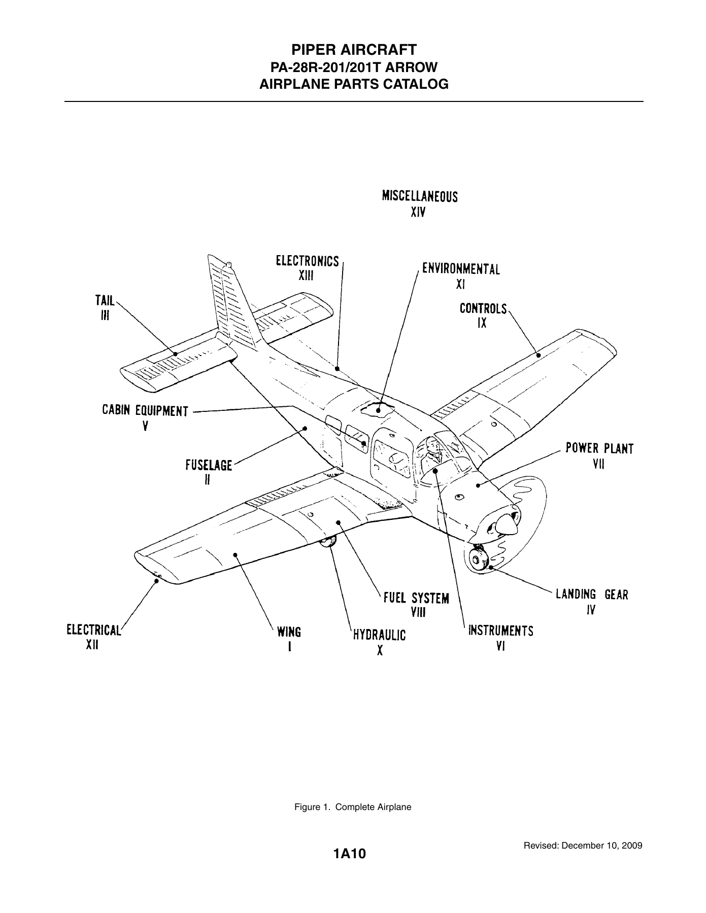
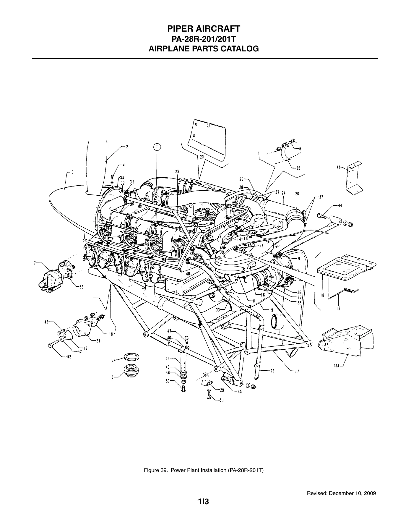
The drawings are a major part of this Piper Arrow parts reference. They include complete-airplane orientation, exploded structural views, landing gear and brake assemblies, cockpit and cabin installations, power plant installations, fuel and control systems, hydraulic components, electrical installations, avionics-related equipment, placards, and other aircraft groups. The PA-28R-201 power plant listing identifies the Lycoming I0-360-C1C6 engine and shows McCauley and Hartzell propeller applications. The PA-28R-201T power plant listing identifies the Continental TSIO-360-FB engine with a Hartzell propeller assembly. Model-specific figures and application codes make it possible to distinguish parts that apply only to the normally aspirated or turbocharged configuration.
The catalog also includes optional-equipment and configuration-dependent references. Examples shown in the document include air conditioning, oxygen-system installations, electric trim and autopilot equipment, ELT installations, alternator arrangements, instrument and radio installations, landing-gear-related equipment, cold-weather and winterization items, and other production or optional configurations. Applicability notes should be checked against the aircraft model and serial number before selecting a part.
Chapters Covered
- Section I – Wing Group: Wing Installation; Wing Leading Edge Assembly; Wing Trailing Edge Assembly; Aileron Assembly; Flap Assembly.
- Section II – Fuselage Group: Complete Fuselage Assembly; Upper Forward Cockpit; Upper Center Cockpit; Lower Forward Cockpit; Lower Aft Cockpit; Aft Section; Cabin and Baggage Door Installation; Fuselage Enclosure Installation.
- Section III – Tail Surfaces Group: Tail Surfaces Installation; Stabilator Assembly; Fin Assembly; Rudder Assembly.
- Section IV – Landing Gear Group: Nose Landing Gear Installation and Assembly; Cleveland and McCauley Nose Wheel Assemblies; Main Landing Gear Installation and Assembly; Main Wheel Assembly; Brake Assembly; PA-28R-201 and PA-28R-201T Landing Gear Door Installations; Hand Brake; Toe Brake; Toe Brake Master Cylinder.
- Section V – Cabin Equipment Group: Cockpit Finishing; Window Curtains; Carpet; Seats; Vertically Adjustable Front Seat Assembly.
- Section VI – Instruments Group: Instrument Panel Installations; Vacuum System; Auxiliary Vacuum Pump; Pitot Static System.
- Section VII – Power Plant Group: PA-28R-201 and PA-28R-201T Power Plant Installations; PA-28R-201T Engine Instrument Lines; PA-28R-201 Exhaust System; Engine Baffles; Engine Cowls; McCauley and Hartzell Propeller Assemblies; Engine Controls.
- Section VIII – Fuel System Group: PA-28R-201 Fuel System; PA-28R-201T Fuel System; Fuel Tank Assembly.
- Section IX – Control System Group: Control System Installation; Flap Controls; Stabilator Trim; Rudder Trim Mechanism; Control Wheel; Rudder Pedals.
- Section X – Hydraulic System Group: Hydraulic System Installation figures and associated parts listings.
- Section XI – Environmental Group: Heat and Defrost Systems; Fresh Air Ventilation; Air Conditioning Compressor, Refrigerant Lines, Ducts, Evaporator and Condenser; Oxygen System installations.
- Section XII – Electrical System Group: Electrical System; Instrument Panel Electrical Installation; Air Conditioning Electrical; Battery; External Power Supply; Chrysler and Prestolite Alternators; Strobe Lights.
- Section XIII – Electronics Group: Electric Trim; AutoFlite II; AutoControl III B; multiple Piper Automatic Locator/ELT installations; Radar Altimeter; Narco AR 500 Encoder; Radio, Antenna and Static Wicks; Audio Selector; Radio Installation Drawings.
- Section XIV – Miscellaneous Group: Placards and Exterior Stencils; Optional Equipment Kits; Repair Kits; Numerical Index.
Taken together, the fourteen groups provide a systematic parts-identification path from major airframe assemblies down to individual hardware and components. The numerical index at the rear gives another way to trace part numbers back to the relevant figure and index location, while the optional-equipment and repair-kit listings cover additional cataloged configurations and service items.
Important Use Note
This is a parts catalog intended for positive identification of replacement parts. The document specifically states that it is not to be used for rigging and installation purposes. For part selection, the aircraft model, serial number, figure code, and serial-number applicability shown in the catalog should be matched carefully. Where the catalog points to a Piper Service Bulletin, Service Letter, or vendor publication, that reference forms part of the applicability information shown for the affected item.
Find the Correct Piper Arrow Parts Reference
The Piper PA-28R-201 / PA-28R-201T Arrow Illustrated Airplane Parts Catalog 761-638 – 2009 PDF gives owners, maintenance personnel, restorers, parts departments, and aircraft operators a structured way to identify the correct replacement component, compare assembly relationships, verify part numbers, and check serial-number-specific applications before ordering. The combination of exploded illustrations, detailed nomenclature, quantity information, model codes, and affected serial ranges helps reduce uncertainty when tracing a component through the aircraft’s airframe, landing gear, power plant, fuel, control, hydraulic, electrical, instrument, environmental, and electronics systems.
IMAGES PREVIEW
Correct part identification matters because apparently similar components can differ by model, production range, installed equipment, or revision. This catalog keeps those distinctions visible in the same reference. After purchase, the manual is delivered as an instant PDF download with no shipping required. It can be opened on common computers, tablets, and phones, and pages can be printed when a paper reference is useful at the aircraft, workbench, or parts counter.
Reviews
There are no reviews yet.