
Piper PA-32-301 & PA-32-301T Saratoga Maintenance Manual 761 721 PDF
Original price was: $44.95.$26.95Current price is: $26.95.
Complete Piper PA-32-301 and PA-32-301T Saratoga maintenance manual, Piper part number 761 721, in GAMA chapter format. Covers airframe, Lycoming IO-540 and TIO-540 power plants, Hartzell propellers, landing gear, brakes, fuel, electrical, avionics, oxygen, vacuum, structures, rigging and electrical schematics. Instant PDF download.
Description
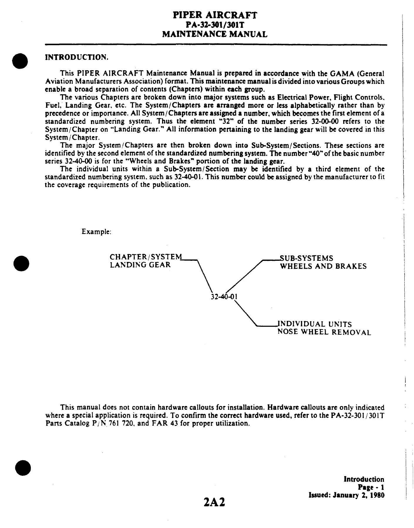
The Piper PA-32-301 and PA-32-301T Saratoga Maintenance Manual (Piper part number 761 721) is the full GAMA-format service document for the normally aspirated PA-32-301 and the turbocharged PA-32-301T. It spans the airframe, engine, propeller, systems and avionics in the standardized chapter numbering Piper used across the Saratoga line, running from Chapter 4 Airworthiness Limitations through Chapter 95 Special Purpose Equipment. This is the working reference a shop reaches for when a Saratoga comes in for inspection, troubleshooting, rigging, or a component overhaul – not a condensed owner’s handbook and not a generic light-aircraft guide.
File Details
- Manual type: Aircraft maintenance manual (GAMA format)
- Brand / manufacturer: Piper Aircraft Corporation
- Models covered: PA-32-301, PA-32-301T Saratoga
- Piper part number: 761 721
- Original issue: January 2, 1980
- Material revised through: August 15, 1985, with interim revisions effective April 30, 1986, July 30, 1986, September 20, 1986 and March 16, 1987
- Language: English
- Page count: 674 pages
- File format: PDF
- Delivery: Instant download, no shipping
Chapters Covered in This Piper Saratoga Maintenance Manual
- Chapter 4 – Airworthiness Limitations
- Chapter 5 – Time Limits and Maintenance Checks: inspection requirements, preflight checks, overlimits inspection, scheduled maintenance, periodic inspections, programmed inspection, unscheduled maintenance checks
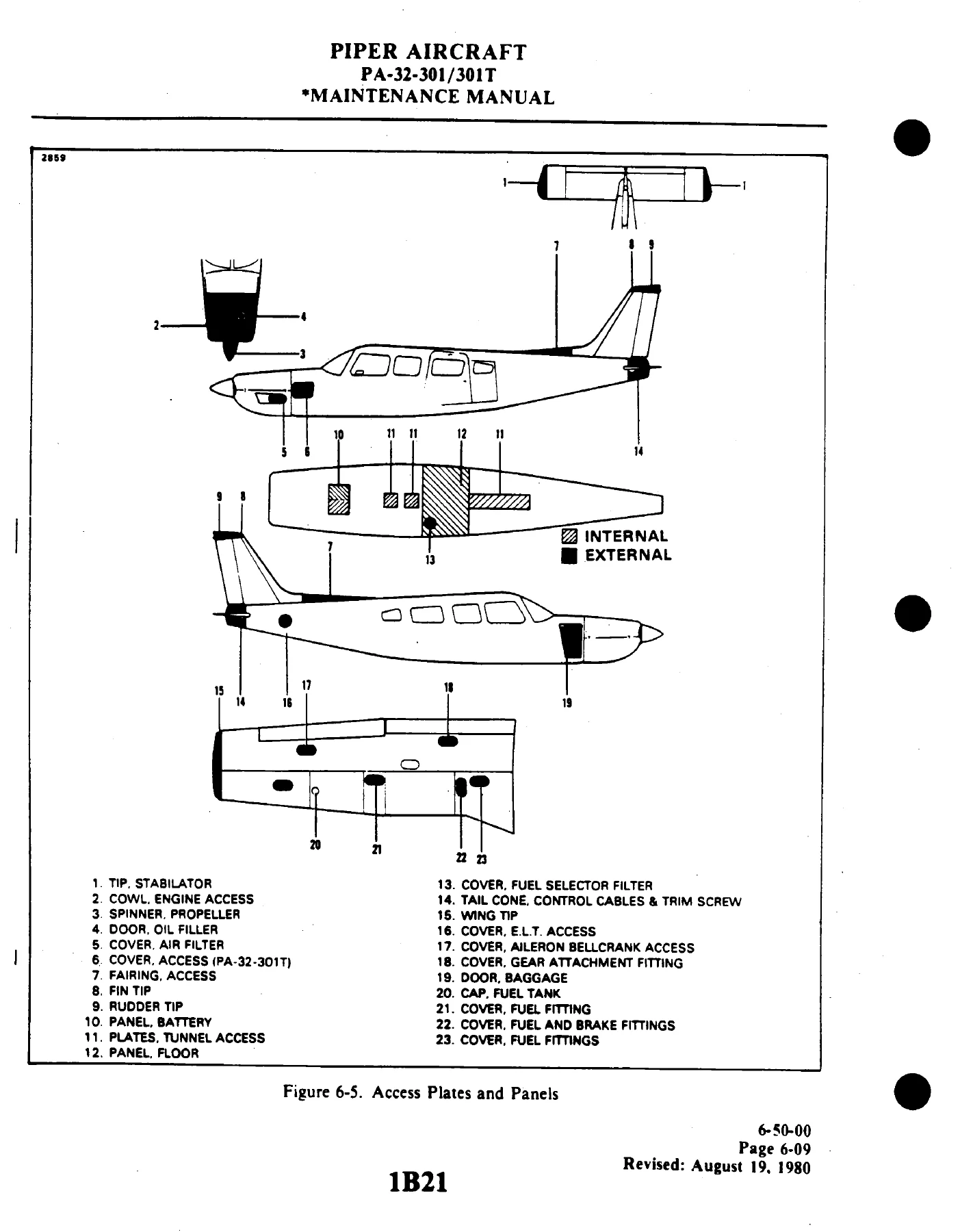
- Chapter 6 – Dimensions and Areas: leading particulars, station reference lines, access and inspection provisions, weight and balance data, serial number plate
- Chapter 7 – Lifting and Shoring
- Chapter 8 – Leveling and Weighing
- Chapter 9 – Towing and Taxiing
- Chapter 10 – Parking and Mooring
- Chapter 11 – Required Placards
- Chapter 12 – Servicing and Lubrication: fuel system, landing gear oleo struts, brake system, tires and tire balancing, power plant and engine air filter, propeller, electrical system and battery, lubrication charts, winterization plate
- Chapter 20 – Standard Practices (Airframe): torque wrenches and adapter formula, rod end bearing installation, Cherrylock rivet removal, fluid line identification, flexible hose assemblies, flareless tube assemblies, support clamps, aircraft finish care and cleaning
- Chapter 21 – Environmental System: cabin vent system and overhead blower, heating and defrost, air conditioning including compressor service, magnetic clutch, receiver-dehydrator, condenser and door actuator rigging, expansion valve, evaporator, service valves, leak checks, evacuation and charging
- Chapter 22 – Autoflight
- Chapter 23 – Communications: Emergency Locator Transmitter battery removal and installation, testing, pilot’s remote switch
- Chapter 24 – Electrical Power: Prestolite and 90 amp Ford alternator systems, disassembly and assembly, rectifier and rotor testing, battery servicing and testing, voltage regulator, overvoltage relay, external power, electrical system load distribution
- Chapter 25 – Equipment and Furnishings: seat back lock and release rigging, shoulder harness inertia reel adjustment
- Chapter 27 – Flight Controls: control column assembly, aileron and tab, aileron/rudder interconnect, rudder and tab, rudder trim, rudder and steering pedal assembly, stabilator and tab, stabilator trim, flaps, stall warning horn and lift detector
- Chapter 28 – Fuel: inboard tanks and outboard fuel cells, fuel cell inspection and repair, molded nipple fittings, fuel selector valve and filter, electric fuel pump, fuel quantity sender unit and gauge check
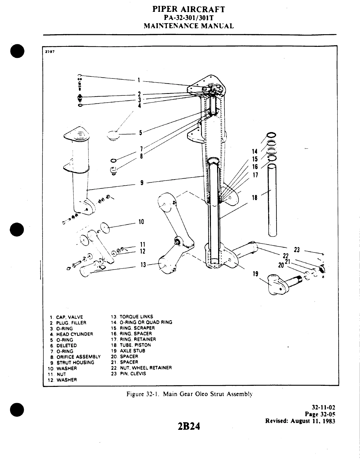
- Chapter 32 – Landing Gear: main gear oleo, nose gear oleo, nose gear alignment, main and nose wheels, brakes and lining tolerance, brake master cylinder, toe brake cylinder, gravity and pressure bleeding, wheel fairings
- Chapter 33 – Lights: instrument and panel lights, dimmer control assembly, switch panel assembly, annunciator panel, landing light, rotating beacon, wing tip strobe and strobe power supply
- Chapter 34 – Navigation and Pitot/Static: face mounted and cluster mounted instruments, rate of climb indicator, sensitive altimeter, airspeed indicator, gyro horizon, directional gyro, magnetic compass compensation, turn and bank indicator
- Chapter 35 – Oxygen: fixed and portable systems, Swagelok fitting installation, Teflon tape thread sealant, leak tests, oxygen cylinder and regulator, recharge valve, pressure gauge, refilling pressures
- Chapter 37 – Vacuum: vacuum pump, regulator valve adjustment, vacuum gauge and sensor
- Chapter 39 – Electrical Panels, Parts and Instruments: switches and circuit breakers
- Chapter 51 – Structures: fiberglass touch-up, fracture and patch repairs, thermoplastic repairs, safety walk repair
- Chapter 52 – Doors: forward and aft cabin door, latch mechanism, lock assembly, safety latch, door snubber, baggage door and hinge
- Chapter 55 – Stabilizers: stabilator removal and balancing, control surface free play, vertical fin, rudder removal and balancing
- Chapter 56 – Windows: windshield removal and installation, single pane side windows
- Chapter 57 – Wings: wing tip, attach fittings, wing removal and installation, aileron, aileron balancing, wing flap
- Chapter 61 – Propellers: Hartzell propeller removal and installation, blade nicks and removal method, blade track, propeller governor rigging and adjustment
- Chapter 70 – Standard Practices (Engines)
- Chapter 71 – Power Plant: engine removal and installation for both variants, cowling removal, installation and repair
- Chapter 73 – Engine Fuel System: Bendix RSA fuel injection, fuel-air bleed nozzles, idle speed and mixture adjustment, throttle and mixture control adjustment
- Chapter 74 – Ignition: D-2000 series magnetos, inspection, magneto-to-engine timing and internal timing, impulse coupling, harness maintenance, spark plugs, ignition switch
- Chapter 77 – Engine Indicating: manifold pressure gauge, tachometer, oil pressure gauge, oil temperature indicator, exhaust gas temperature gauge, cylinder head temperature gauge
- Chapter 78 – Exhaust: exhaust system inspection
- Chapter 79 – Oil System: oil cooler installation, oil pressure sensor
- Chapter 80 – Starting: gear reduction starting motor overhaul, brush, armature and field coil service, Bendix drive, bench testing
- Chapter 81 – Turbines: engine turbocharger, lubrication system priming, exhaust wastegate assembly adjustment, turbocharger decoking, throttle control stop limits
- Chapter 91 – Charts and Wiring Diagrams: tube and hose torque, recommended nut torques, decimal and metric conversions, list of consumable materials, electrical wire coding, electrical symbols and the full electrical schematic index
- Chapter 95 – Special Purpose Equipment: fabricated rigging tools, tire balancer, orifice replacement tool, baggage door lock tool, control surface balancing tool
Read end to end, this Piper Saratoga maintenance manual gives a technician a single continuous reference instead of a shelf of loose service letters. The front chapters establish the inspection intervals and the placard, servicing and lubrication baseline for the airframe. From there each system chapter carries its own troubleshooting chart with probable causes and remedies, followed by removal, disassembly, cleaning and inspection, assembly and installation procedures, and where needed the rigging or adjustment values that put the component back within limits. The torque tables, conversion charts, consumable materials list and electrical schematic index at the back tie the whole thing together so a job can be finished without leaving the document.
Engines, Propellers and Serial Coverage
The manual is written for two distinct power plants, and the procedures are split accordingly wherever the turbocharged installation differs. The PA-32-301 uses the Avco-Lycoming IO-540-K1G5D rated at 300 hp at 2700 rpm. The PA-32-301T uses the Avco-Lycoming TIO-540-S1AD, with take-off power of 300 hp at 2700 rpm and 36 in. hg. for a maximum five minute limit, and maximum continuous power of 270 hp at 2575 rpm and 33 in. hg. Both variants run Hartzell constant speed propellers with their own hub and blade combinations, and the propeller chapter covers removal, installation, blade track and governor rigging.
Because Piper issued running changes across the production life of both models, several chapters call out different procedures by aircraft serial number. Electrical schematics in Chapter 91, for example, are indexed by serial ranges across the PA-32-301 and PA-32-301T lines, and inspection items such as the electric flap selector handle and screw jack apply from S/N 32-85- and up. Serial ranges visible in the document include the PA-32-301 ranges beginning at 32-8006001 and the PA-32-301T ranges beginning at 32-8024001, with later breaks at 32-8106088, 32-8106099, 32-8124031 and 32-8224001. Checking your airframe serial against the applicable index before starting a job is part of using this manual correctly.
What This PA-32-301 / 301T Manual Lets You Do
Practically, this is the document that supports the jobs that actually come through the hangar door on a Saratoga. Inspections can be run against the 50, 100, 500 and 1000 hour interval tables, with the note references that point to the correct service bulletin or service letter. Landing gear work is covered down to the oleo strut internals – filling the main and nose gear struts, inflating to the correct piston exposure, replacing the scraper ring and O-ring seals, and setting nose gear alignment with the rudder pedals clamped neutral. Brake work includes lining thickness limits, disc minimum thickness, anchor bolt replacement with the arbor press fixture, master cylinder and toe brake cylinder assembly, and both gravity and pressure bleeding procedures.
On the systems side, the manual walks through air conditioning discharge, evacuation and charging with the manifold gauge set and charging stand, the alternator overhaul on both the Prestolite and Ford units with rotor, stator, rectifier and diode tests, the vacuum pump and regulator, and the fixed oxygen system from Swagelok fitting installation through leak testing and refilling pressures. Structures work covers fiberglass fracture and patch repair, thermoplastic repair, and safety walk replacement.
For flight controls and rigging, the chapters give the cable tensions, travel limits and rigging tool dimensions needed to bring aileron, rudder, stabilator and flap systems back into specification, along with the control surface balancing procedures and their limits. Ignition work runs from internal magneto timing and breaker synchronization through harness repair and spark plug servicing, and the turbocharged variant gets its own turbocharger, wastegate and decoking material.
Why Correct Procedures and Specifications Matter
An airframe like the PA-32-301 is unforgiving of guesswork in a few specific places. Cable tension that is close but not corrected for ambient temperature will not hold rigging. Oleo struts filled to an eyeballed level rather than the specified piston exposure will bottom out or ride harsh. Brake linings run past the wear limit, or a disc machined below minimum thickness, will fail when it is needed most. Torque values applied from memory rather than from the table can stretch a bolt or crush a fitting. This manual exists because those values are not universal – they are specific to this airframe, these engines and these systems, and they are recorded here with the surrounding procedure so the number is not used in isolation.
IMAGES PREVIEW
Instant PDF Delivery
The complete Piper PA-32-301 and PA-32-301T Saratoga maintenance manual, part number 761 721, is delivered as an instant PDF download the moment your order completes. There is no shipping, no waiting on a physical binder, and no risk of a missing card. The file opens on any laptop, tablet or phone and every page can be printed for the shop floor, so the inspection table can sit on the cowling while the schematic stays open on the screen. Whether you are an owner maintaining your own Saratoga, an IA working through an annual, or a shop taking on a 301 or 301T for the first time, this is the reference that keeps the work inside the numbers.

Reviews
There are no reviews yet.