★ TRUSTED BY 321,897+ PROFESSIONALS WORLDWIDE
🏢
Trusted Business
Verified & Licensed
🛡️
Virus Free Files
100% Safe Downloads
🔒
Secure Payment
SSL Protected
Instant Delivery
Available Immediately
Sale!

Airbus A318 A319 A320 A321 Aircraft Maintenance Manual Chapter 28 Fuel Rev 40 – 2012

Original price was: $49.95.Current price is: $29.95.

Airbus A318, A319, A320 and A321 Aircraft Maintenance Manual Chapter 28 covering fuel-system description, servicing, tank work, distribution, pumps, crossfeed, refuel/defuel, fuel quantity indication and related inspection, test, removal and installation procedures. AES Revision 40 dated May 01/12, 2149 pages in PDF format.

Instant PDF Download
Available immediately
💾
Save to Your Device
Download & keep forever
🛡️
Antivirus Scanned
100% virus-free
🌍
Trusted Worldwide
175,000+ customers

Description

Airbus A318 A319 A320 A321 Aircraft Maintenance Manual Chapter 28 Fuel Rev 40 – 2012

The Airbus A318 A319 A320 A321 Aircraft Maintenance Manual Chapter 28 Fuel Rev 40 – 2012 is a dedicated Chapter 28 reference for the fuel systems used across the A318, A319, A320 and A321 aircraft families. Its coverage goes well beyond a basic system overview: the manual brings together fuel-system description and operation, servicing, maintenance practices, deactivation and reactivation, adjustment and test, inspection and check, cleaning, repair, and component removal and installation tasks. The material is organized by ATA-style section and component reference, making it useful when the work involves tanks, pumps, valves, venting, transfer, refuel/defuel, quantity indication or fuel level sensing.

Across its 2149 pages, this Airbus Chapter 28 Fuel maintenance manual provides detailed task references and illustrated figures for the wing and center tank fuel system, cockpit and refuel controls, electrical supplies and interfaces, tank access and bonding, fuel distribution and pumping, and the sensing and indication equipment used to monitor fuel quantity and tank conditions. Revision markings throughout the document identify AES Revision 40 with the date May 01/12.

File Details

  • Manual type: Aircraft Maintenance Manual – Chapter 28 Fuel
  • Brand: Airbus
  • Models covered: A318, A319, A320, A321
  • Language: English
  • Page count: 2149
  • File format: PDF
  • Revision: 40
  • Date: May 01/12

Fuel-System Maintenance Scope

The manual starts with fuel-system general information and then moves through the principal storage, distribution and indication functions. General fuel content includes the wing and center tank arrangement, control switches, engine and APU fire-button interfaces, ECAM displays, the refuel/defuel control panel, electrical power supplies, electrical symbols, interfaces and a fuel-system block diagram. The servicing material includes fuel safety procedures and approved fuels, while maintenance tasks include fuel-pipe removal and installation, tank-bonding inspection and bonding-strip repair.

Fuel tank work is treated as a substantial maintenance area in its own right. The storage and tanks sections include safety procedures for work in fuel tanks, dry-tank precautions, tank access, purge and vent procedures, water-drain and clack-valve work, microbiological contamination treatment, center-tank preservation, multiple fuel-tank leak-test methods, leak analysis, tank inspection and tank cleaning. The manual also contains illustrated tank and access details that support these procedures.

Ventilation and tank protection coverage includes the tank venting system, overpressure protectors, float vent valves, fuel-drain check valves, NACA vent components, the wing center tank external ventilating system, vapor seals, drain mast and leak monitor. The Chapter 28 material also addresses tank ignition prevention, including inspections of bonding leads, electrical wiring, FQI probe harnesses, fuel-pump canisters and center wing box areas.

Distribution and feed functions are covered from the main fuel-pump system through the APU fuel-pump system, crossfeed, engine LP fuel shut off and APU LP fuel shut off. Tasks include operational and functional tests, leak checks, pump and pressure-switch work, check and suction valves, air-release valves, sequence valves, fuel-pump canisters, water-scavenge jet pumps, strainers and the related actuator or valve removal and installation procedures. Refuel/defuel coverage extends to the control system and its associated couplings, diffusers, valves, actuators, panel components and checks.

The indicating portion of the Airbus A318 A319 A320 A321 Chapter 28 Fuel manual covers fuel quantity indicating, manual magnetic indicators and tank level sensing. Component coverage includes fuel-quantity probes, the fuel quantity preselector and indicator, the Fuel Quantity Indicating Computer, tank harnesses, magnetic level indicators, high/low level sensors, overflow and temperature sensing, and the Fuel Level Sensing Control Unit. This gives maintenance personnel a single Chapter 28 reference spanning the physical fuel system and the electrical sensing and indication functions that support it.

Complete PDF Bookmark Tree

Complete Bookmarks

The complete bookmarks in the “Airbus A318 A319 A320 A321 Aircraft Maintenance Manual Chapter 28 Fuel Rev 40 – 2012” are as follows:

Manual Front Matter
Chapter 05 – TIME LIMITS – MAINTENANCE CHECKS
Chapter 06 – DIMENSIONS AND AREAS
Chapter 07 – LIFTING AND SHORING
Chapter 08 – LEVELING AND WEIGHING
Chapter 09 – TOWING AND TAXIING
Chapter 10 – PARKING, MOORING, STORAGE & RETURN TO SERVICE
Chapter 11 – PLACARDS AND MARKINGS
Chapter 12 – SERVICING
Chapter 20 – STANDARD PRACTICES – AIRFRAME
Chapter 21 – AIR CONDITIONING
Chapter 22 – AUTO FLIGHT
Chapter 23 – COMMUNICATIONS
Chapter 24 – ELECTRICAL POWER
Chapter 25 – EQUIPMENT/FURNISHINGS
Chapter 26 – FIRE PROTECTION
Chapter 27 – FLIGHT CONTROLS
Chapter 28 – FUELp. 1
Table of Contentsp. 1
28-00 – FUEL – GENERALp. 29
28-00-00 – FUEL – GENERALp. 29
28-00-00 PB 001 CONF 00 – FUEL – GENERAL – DESCRIPTION AND OPERATIONp. 29
Generalp. 29
Component Locationp. 30
System Descriptionp. 31
Power Supplyp. 36
Interfacesp. 37
Operation/Control and Indicatingp. 38
BITE Testp. 40
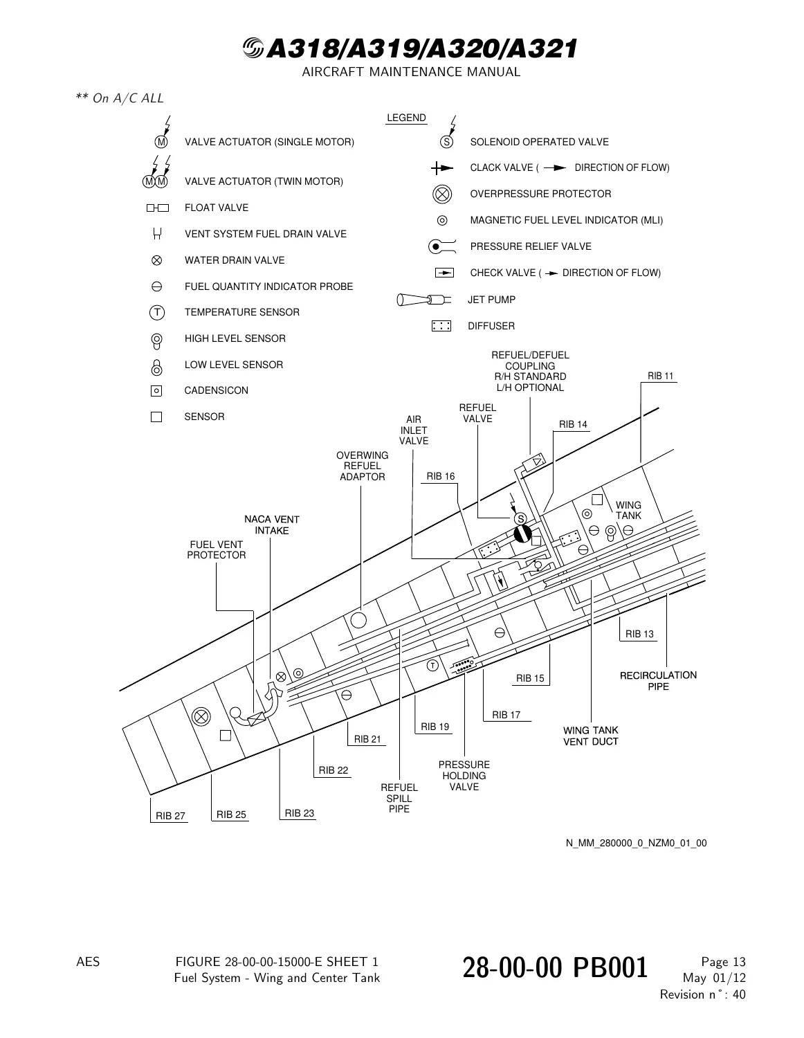
Figure 28-00-00-15000-E – Fuel System – Wing and Center Tankp. 41
Figure 28-00-00-15700-C – Fuel System Control Switchesp. 45
Figure 28-00-00-16000-A – Engine and APU Fire Buttons and Engine Start Switchesp. 46
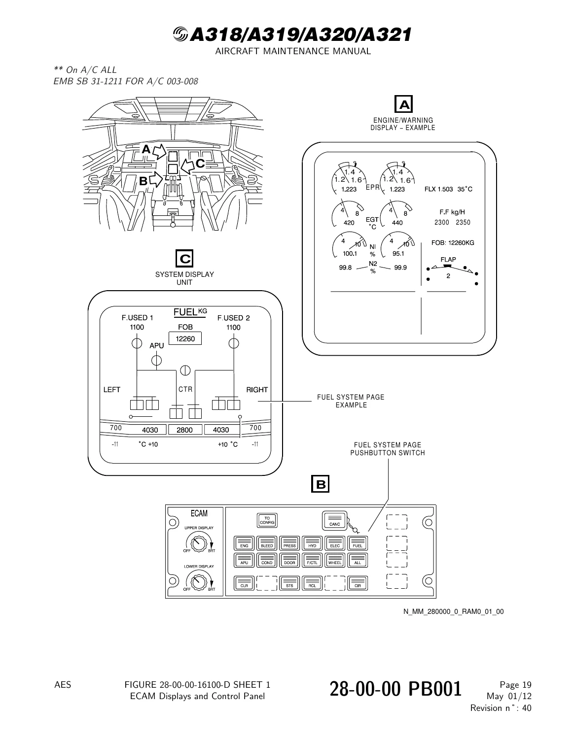
Figure 28-00-00-16100-D – ECAM Displays and Control Panelp. 47
Figure 28-00-00-16700-A – Refuel/Defuel Control Panel 800VUp. 48
Figure 28-00-00-24500-E – Fuel System – Electrical Power Suppliesp. 49
Figure 28-00-00-26000-A – Fuel System – Electrical Symbolsp. 52
Figure 28-00-00-27300-A – Fuel System – Interfacesp. 54
Figure 28-00-00-27300-B – DELETEDp. 55
Figure 28-00-00-27400-A – Fuel System – Block Diagramp. 56
Figure 28-00-00-29500-A – Standard Envelope – Fuelp. 57
28-00-00 PB 301 CONF 00 – FUEL – GENERAL – SERVICINGp. 58
28-00-00-910-001-A – Fuel Safety Proceduresp. 58
28-00-00-650-001-A – Approved Fuelsp. 60
28-00-00 PB 401 CONF 00 – FUEL – GENERAL – DEACTIVATION/REACTIVATIONp. 62
28-00-00-000-001-A – Removal of the Fuel Pipesp. 62
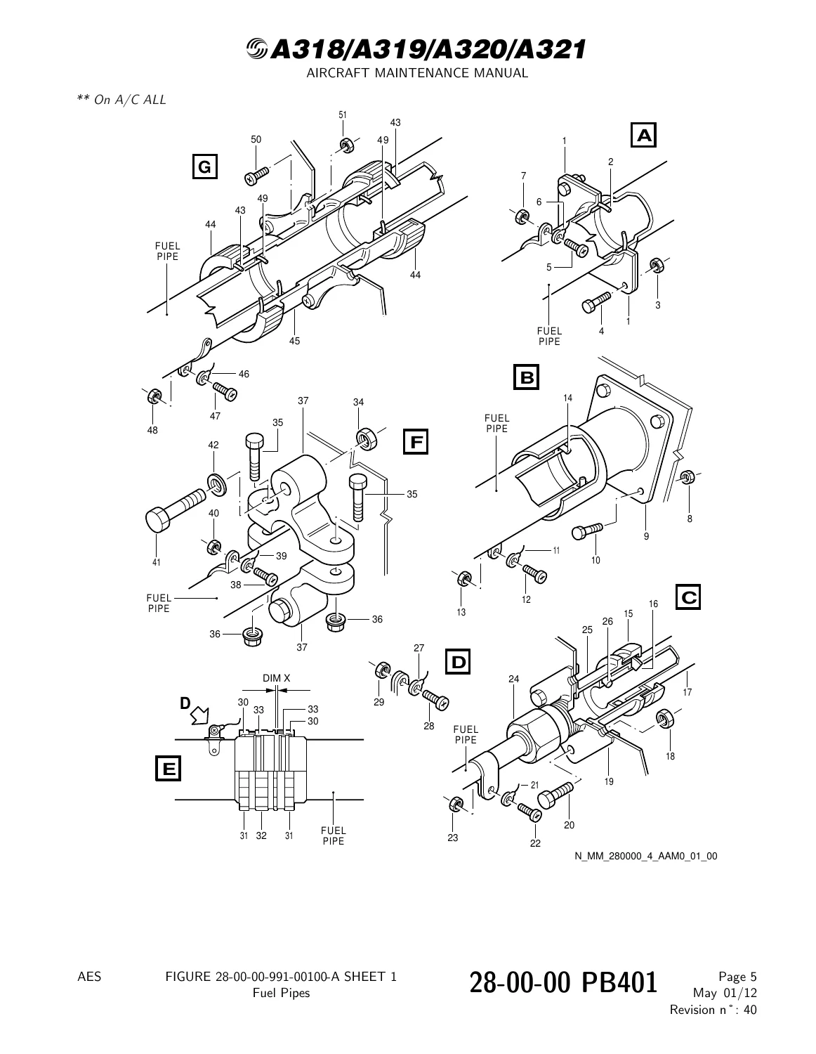
Figure 28-00-00-991-00100-A – Fuel Pipesp. 66
28-00-00-400-001-A – Installation of the Fuel Pipesp. 67
28-00-00 PB 601 CONF 00 – FUEL – GENERAL – INSPECTION/CHECKp. 72
28-00-00-200-001-A – Inspection of the Fuel Tank Bondingp. 72
Figure 28-00-00-991-06700-A – Bonding Strap Inspection Report Sheetp. 78
Figure 28-00-00-991-06800-A – Manhole Access, Wing Fuel Tanksp. 79
Figure 28-00-00-991-06900-A – Fuel Quantity Indicator Harness, Fuel Sensor and Probe Locationsp. 80
Figure 28-00-00-991-07000-A – Water Drain Valve and Magnetic Level Indicator Locationsp. 81
Figure 28-00-00-991-01700-A – Bonding Detail, RIB 1 to RIB 2, Left Handp. 82
Figure 28-00-00-991-01800-A – Bonding Detail, RIB 2 to RIB 3, Left Handp. 84
Figure 28-00-00-991-01900-A – Bonding Detail, RIB 3 to RIB 4, Left Handp. 86
Figure 28-00-00-991-02000-A – Bonding Detail, RIB 4 to RIB 5, Left Handp. 88
Figure 28-00-00-991-02100-A – Bonding Detail, RIB 5 to RIB 6, Left Handp. 90
Figure 28-00-00-991-02200-A – Bonding Detail, RIB 6 to RIB 7, Left Handp. 92
Figure 28-00-00-991-02300-A – Bonding Detail, RIB 7 to RIB 8, Left Handp. 94
Figure 28-00-00-991-02400-A – Bonding Detail, RIB 8 to RIB 9, Left Handp. 96
Figure 28-00-00-991-02500-A – Bonding Detail, RIB 9 to RIB 10, Left Handp. 98
Figure 28-00-00-991-02600-A – Bonding Detail, RIB 10 to RIB 11, Left Handp. 100
Figure 28-00-00-991-02700-A – Bonding Detail, RIB 11 to RIB 12, Left Handp. 102
Figure 28-00-00-991-02800-A – Bonding Detail, RIB 12 to RIB 13, Left Handp. 104
Figure 28-00-00-991-02900-A – Bonding Detail, RIB 13 to RIB 14, Left Handp. 106
Figure 28-00-00-991-03000-A – Bonding Detail, RIB 14 to RIB 15, Left Handp. 108
Figure 28-00-00-991-03100-A – Bonding Detail, RIB 15 to RIB 16, Left Handp. 110
Figure 28-00-00-991-03200-A – Bonding Detail, RIB 16 to RIB 17, Left Handp. 112
Figure 28-00-00-991-03300-A – Bonding Detail, RIB 17 to RIB 18, Left Handp. 114
Figure 28-00-00-991-03400-A – Bonding Detail, RIB 18 to RIB 19, Left Handp. 116
Figure 28-00-00-991-03500-A – Bonding Detail, RIB 19 to RIB 20, Left Handp. 118
Figure 28-00-00-991-03600-A – Bonding Detail, RIB 20 to RIB 21, Left Handp. 120
Figure 28-00-00-991-03700-A – Bonding Detail, RIB 21 to RIB 22, Left Handp. 122
Figure 28-00-00-991-03800-A – Bonding Detail, RIB 22 to RIB 23, Left Handp. 124
Figure 28-00-00-991-03900-A – Bonding Detail, RIB 23 to RIB 24, Left Handp. 125
Figure 28-00-00-991-04000-A – Bonding Detail, RIB 24 to RIB 25, Left Handp. 126
Figure 28-00-00-991-04100-A – Bonding Detail, RIB 25 to RIB 26, Left Handp. 127
Figure 28-00-00-991-12800-A – Bonding Detail, RIB 26 to RIB 27, Left Handp. 128
Figure 28-00-00-991-04200-A – Bonding Detail, RIB 1 to RIB 2, Right Handp. 129
Figure 28-00-00-991-04300-A – Bonding Detail, RIB 2 to RIB 3, Right Handp. 131
Figure 28-00-00-991-04400-A – Bonding Detail, RIB 3 to RIB 4, Right Handp. 133
Figure 28-00-00-991-04500-A – Bonding Detail, RIB 4 to RIB 5, Right Handp. 135
Figure 28-00-00-991-04600-A – Bonding Detail, RIB 5 to RIB 6, Right Handp. 137
Figure 28-00-00-991-04700-A – Bonding Detail, RIB 6 to RIB 7, Right Handp. 139
Figure 28-00-00-991-04800-A – Bonding Detail, RIB 7 to RIB 8, Right Handp. 141
Figure 28-00-00-991-04900-A – Bonding Detail, RIB 8 to RIB 9, Right Handp. 143
Figure 28-00-00-991-05000-A – Bonding Detail, RIB 9 to RIB 10, Right Handp. 145
Figure 28-00-00-991-05100-A – Bonding Detail, RIB 10 to RIB 11, Right Handp. 147
Figure 28-00-00-991-05200-A – Bonding Detail, RIB 11 to RIB 12, Right Handp. 149
Figure 28-00-00-991-05300-A – Bonding Detail, RIB 12 to RIB 13, Right Handp. 151
Figure 28-00-00-991-05400-A – Bonding Detail, RIB 13 to RIB 14, Right Handp. 153
Figure 28-00-00-991-05500-A – Bonding Detail, RIB 14 to RIB 15, Right Handp. 155
Figure 28-00-00-991-05600-A – Bonding Detail, RIB 15 to RIB 16, Right Handp. 157
Figure 28-00-00-991-05700-A – Bonding Detail, RIB 16 to RIB 17, Right Handp. 159
Figure 28-00-00-991-05800-A – Bonding Detail, RIB 17 to RIB 18, Right Handp. 161
Figure 28-00-00-991-05900-A – Bonding Detail, RIB 18 to RIB 19, Right Handp. 163
Figure 28-00-00-991-06000-A – Bonding Detail, RIB 19 to RIB 20, Right Handp. 165
Figure 28-00-00-991-06100-A – Bonding Detail, RIB 20 to RIB 21, Right Handp. 167
Figure 28-00-00-991-06200-A – Bonding Detail, RIB 21 to RIB 22, Right Handp. 169
Figure 28-00-00-991-06300-A – Bonding Detail, RIB 22 to RIB 23, Right Handp. 171
Figure 28-00-00-991-06400-A – Bonding Detail, RIB 23 to RIB 24, Right Handp. 172
Figure 28-00-00-991-06500-A – Bonding Detail, RIB 24 to RIB 25, Right Handp. 173
Figure 28-00-00-991-06600-A – Bonding Detail, RIB 25 to RIB 26, Right Handp. 174
Figure 28-00-00-991-12900-A – Bonding Detail, RIB 26 to RIB 27, Right Handp. 175
Figure 28-00-00-991-13000-A – Crossfeed Valve 10QM, APU Fuel Pump 9QM Locationsp. 176
Figure 28-00-00-991-13100-A – Defuel Transfer Valve 11QM Locationp. 177
28-00-00-200-002-A – Dimensional Inspection of the Dowel (Anti-Rotation) on Twin Motor Actuatorsp. 178
Figure 28-00-00-991-12500-A – Actuator Dowel (Anti-Rotation) – Dimensional Inspectionp. 180
28-00-00 PB 801 CONF 00 – FUEL – GENERAL – REPAIRSp. 181
28-00-00-300-001-A – Repair of the Bonding Strip Attachmentp. 181
Figure 28-00-00-991-00200-A – Bonding Clip-Repair Detailp. 184
28-10 – STORAGEp. 185
28-10-00 – STORAGEp. 185
28-10-00 PB 001 CONF 00 – STORAGE – DESCRIPTION AND OPERATIONp. 185
Generalp. 185
Component Locationp. 186
System Descriptionp. 187
Power Suppliesp. 188
Interfacesp. 189
Figure 28-10-00-12300-B – Tanks – Component Locationp. 190
Figure 28-10-00-18100-A – Tanks – Power Suppliesp. 193
Figure 28-10-00-19300-A – Tanks – Interfacesp. 194
28-10-00 PB 301 CONF 00 – STORAGE – SERVICINGp. 195
28-10-00-910-001-A – Safety Procedures When You Do Work in a Fuel Tankp. 195
Figure 28-10-00-991-00400-A – fuel Tank Pre-Entry Checklistp. 198
28-10-00-910-003-A – Safety Procedures When You Do Work in a Dry Fuel Tankp. 199
Figure 28-10-00-991-00500-A – Dry Fuel Tank Pre-Entry Checklistp. 202
28-10-00-910-002-A – Access to the Fuel Tanks and the Work Areasp. 203
Figure 28-10-00-991-00100-A – Safety Areas And Precautionsp. 208
28-10-00-910-004-A – Purge and Vent the Fuel Tanks for Maintenancep. 209
28-11 – TANKSp. 212
28-11-00 – TANKSp. 212
28-11-00 PB 001 CONF 00 – TANKS – DESCRIPTION AND OPERATIONp. 212
Generalp. 212
Component Locationp. 213
System Descriptionp. 215
Power Supplyp. 216
Interfacesp. 217
Component Descriptionp. 218
Operation/Control and Indicatingp. 219
BITE Testp. 220
Figure 28-11-00-17400-C – Tanks – Component Locationp. 221
Figure 28-11-00-17600-E – Water Drain Valves – Component Locationp. 222
Figure 28-11-00-30700-C – Tanks – Component Locationp. 223
28-11-00 PB 301 CONF 00 – TANKS – SERVICINGp. 224
28-11-00-600-003-A – Removal of Microbiological Particlesp. 224
28-11-00-600-008-A – Biocidal Shock Treatment for Moderate Contamination – With Fuel Mixed with Biobor Biocidep. 229
28-11-00-600-008-A-01 – Biocidal Shock Treatment for Moderate Contamination – With Fuel Mixed with Kathon Biocidep. 233
28-11-00-600-008-A-02 – Biocidal Shock Treatment for Moderate Contamination – Using Biobor Biocide With a Metered Injection Rigp. 237
28-11-00-600-008-A-03 – Biocidal Shock Treatment for Moderate Contamination – Using Kathon Biocide With a Metered Injection Rigp. 243
28-11-00-600-009-A – Biocidal Shock Treatment for Heavy Contamination – With Fuel Mixed with Biobor Biocidep. 249
28-11-00-600-009-A-01 – Biocidal Shock Treatment for Heavy Contamination – With Fuel Mixed with Kathon Biocidep. 253
28-11-00-600-009-A-02 – Biocidal Shock Treatment for Heavy Contamination – Using Biobor Biocide With a Metered Injection Rigp. 257
28-11-00-600-009-A-03 – Biocidal Shock Treatment for Heavy Contamination – Using Kathon Biocide With a Metered Injection Rigp. 262
28-11-00-600-010-A – Biocidal Preventative Treatment for Aircraft in Long-Term Storage – With Fuel Mixed with Biobor Biocidep. 267
28-11-00-600-010-A-01 – Biocidal Preventative Treatment for Aircraft in Long-Term Storage – With Fuel Mixed with Kathon Biocidep. 268
28-11-00-600-010-A-02 – Biocidal Preventative Treatment for Aircraft in Long-Term Storage – Using Biobor Biocide With a Metered Injection Rigp. 270
28-11-00-600-010-A-03 – Biocidal Preventative Treatment for Aircraft in Long-Term Storage – Using Kathon Biocide With a Metered Injection Rigp. 272
28-11-00-600-011-A – Preservation of a Center Tank (Not in Use)p. 274
28-11-00 PB 501 CONF 00 – TANKS – ADJUSTMENT/TESTp. 277
28-11-00-790-001-A – Leak Test with Fuel of the Wing-Tank Outer-Cellp. 277
Figure 28-11-00-991-01000-A – Intercell-Transfer-Valve Actuators – Location and Detailp. 282
28-11-00-790-002-A – Leak Test with Fuel of the Wing-Tank Outer and Inner Cellsp. 283
28-11-00-790-003-A – Leak Test of the Center Tankp. 289
28-11-00-790-004-A – Leak Test with Fuel of the Vent Surge Tankp. 293
28-11-00-790-005-A – Leak Test of the Wing Tanks and Vent Surge Tank (without Fuel) by the Local Blowing Procedurep. 297
28-11-00-790-006-A – Leak Test of the Wing Tanks and Vent Surge Tank (without Fuel) by the Vacuum and Dye Procedurep. 301
Figure 28-11-00-991-00500-A – NACA Vent Dummy Doorp. 308
28-11-00-790-007-A – Leak Test of the Left Wing and Vent Surge Tanks and the Center Tank (without Fuel) by the Vacuum and Dye Procedurep. 309
28-11-00-790-009-A – Leak Test of the Fuel Tanks – Without Fuel – Helium Procedurep. 316
Figure 28-11-00-991-01200-A – Test Equipment (Helium Procedure) – Installationp. 320
28-11-00 PB 601 CONF 00 – TANKS – INSPECTION/CHECKp. 321
28-11-00-200-001-A – Check for Full and Free Movement of Clack Valvesp. 321
Figure 28-11-00-991-00700-A – Clack Valves – Location and Detailp. 324
28-11-00-200-002-A – Check Leak Monitor for Evidence of Fuel Leakage and Correct Closure of the Valvep. 325
Figure 28-11-00-991-00100-A – Tank Leak Monitor – Drainingp. 327
28-11-00-280-002-A – Structural Fuel Tank Leaks – General Informationp. 328
Figure 28-11-00-991-02800-A – Structural Fuel Leak Reporting Formp. 331
Figure 28-11-00-991-02900-A – Fuel Leakage Typesp. 335
Figure 28-11-00-991-03000-A – Fuel Leak Analysis Chartp. 336
28-11-00-280-003-A – Structural Fuel Leaks – Analysis of the Route, Location of the Source and the Identification of Applicable Leak Testsp. 337
28-11-00 PB 701 CONF 00 – TANKS – CLEANING/PAINTINGp. 340
28-11-00-100-001-A – Cleaning of the Fuel Tanksp. 340
28-11-41 – VALVE – WATER DRAINp. 343
28-11-41 PB 401 CONF 00 – VALVE – WATER DRAIN – REMOVAL/INSTALLATIONp. 343
28-11-41-000-001-A – Removal of the Water Drain Valvep. 343
Figure 28-11-41-991-00100-B – Water Drain Valve – Vent Surge Tankp. 345
28-11-41-400-002-A – Installation of the Water Drain Valvep. 346
28-11-41-000-002-A – Removal of the Water Drain Valvep. 349
Figure 28-11-41-991-00200-C – Water Drain Valve – Outer Cellp. 351
28-11-41-400-003-A – Installation of the Water Drain Valvep. 352
28-11-41-000-003-A – Removal of the Water Drain Valvep. 356
Figure 28-11-41-991-00300-E – Water Drain Valve – Inner Cellp. 358
28-11-41-400-004-A – Installation of the Water Drain Valvep. 359
28-11-41-000-006-A – Removal of the Outer Valvep. 363
Figure 28-11-41-991-00400-A – Outer Valve – Wing Tankp. 365
28-11-41-400-005-A – Installation of the Outer Valvep. 366
28-11-41-000-004-A – Removal of the Water Drain Valvep. 369
Figure 28-11-41-991-00500-A – Water Drain Valve – Center Tankp. 371
28-11-41-400-006-A – Installation of the Water Drain Valvep. 372
28-11-41-000-005-A – Removal of the Outer Valvep. 376
28-11-41-400-007-A – Installation of the Outer Valvep. 378
28-11-42 – CLACK VALVEp. 381
28-11-42 PB 401 CONF 00 – CLACK VALVE – REMOVAL/INSTALLATIONp. 381
28-11-42-000-001-A – Removal of the Clack Valve (RIB 2)p. 381
Figure 28-11-42-991-00100-A – Clack valvep. 383
28-11-42-400-001-A – Installation of the Clack Valve (RIB 2)p. 384
28-11-43 – CAP/ADAPTOR – GRAVITY FILLp. 388
28-11-43 PB 401 CONF 00 – CAP/ADAPTOR – GRAVITY FILL – REMOVAL/INSTALLATIONp. 388
28-11-43-000-001-A – Removal of the Gravity Fill Cap/Adaptorp. 388
Figure 28-11-43-991-00100-A – Gravity Fill Cap/Adaptor.p. 390
28-11-43-400-001-A – Installation of the Gravity Fill Cap/Adaptorp. 391
28-12 – TANK VENTING SYSTEMp. 395
28-12-00 – TANK VENTING SYSTEMp. 395
28-12-00 PB 001 CONF 00 – TANK VENTING SYSTEM – DESCRIPTION AND OPERATIONp. 395
Generalp. 395
Component Locationp. 396
System Descriptionp. 401
Power Suppliesp. 403
Interfacesp. 404
Component Descriptionp. 405
Operation/Control and Indicatingp. 408
BITE Testp. 409
Figure 28-12-00-14000-C – Vent System – Component Locationp. 410
Figure 28-12-00-14600-D – Vent Surge Tankp. 411
Figure 28-12-00-28000-A – Overpressure Protector – Surge Tankp. 412
Figure 28-12-00-28100-B – Overpressure Protector – Wing-Tank Inner-Cellp. 413
Figure 28-12-00-28200-A – Overpressure Protector – Center Tankp. 414
Figure 28-12-00-28300-A – Vent Protectorp. 415
Figure 28-12-00-31800-A – Overpressure Protector 102QM(103QM)p. 416
Figure 28-12-00-32800-B – Vent Float Valvep. 417
28-12-00 PB 401 CONF 00 – TANK VENTING SYSTEM – DEACTIVATION/REACTIVATIONp. 418
28-12-00-040-001-A – De-activation of the Overpressure Protectorp. 418
Figure 28-12-00-991-00500-A – Overpressure Protector 46QM(47QM) – Location and Detailp. 420
28-12-00-440-001-A – Re-activation of the Overpressure Protectorp. 421
28-12-00-040-002-A – De-activation of the Overpressure Protector – FAA Operators Onlyp. 423
Figure 28-12-00-991-00700-A – Transfer Valve Electrical Connector – Overpressure Protector 102QM(103QM) De-activation/Re-activationp. 427
28-12-00-440-002-A – Re-activaton of the Overpressure Protector – FAA Operators Onlyp. 428
28-12-00-040-003-A – To Set the Transfer Valves Open for Flightp. 431
28-12-00 PB 601 CONF 00 – TANK VENTING SYSTEM – INSPECTION/CHECKp. 435
28-12-00-200-001-A – Inspection of the Tank Venting Systemp. 435
Figure 28-12-00-991-00100-B – Tank Venting Systemp. 439
Figure 28-12-00-991-00200-B – Tank Venting Systemp. 440
28-12-00-210-001-A – Visual Check of Vent Surge Tank Burst Disc (EXTERNAL)p. 441
Figure 28-12-00-991-02000-A – Vent Surge Tank Burst Disc – Location and Detailp. 443
28-12-41 – PROTECTOR – OVERPRESSUREp. 444
28-12-41 PB 401 CONF 00 – PROTECTOR – OVERPRESSURE – REMOVAL/INSTALLATIONp. 444
28-12-41-000-001-A – Removal of the Overpressure Protectorp. 444
Figure 28-12-41-991-00300-A – Overpressure Protector – Vent Surge Tank.p. 446
28-12-41-400-001-A – Installation of the Overpressure Protectorp. 447
28-12-41-000-002-A – Removal of the Overpressure Protectorp. 451
Figure 28-12-41-991-00400-C – Overpressure Protector – Inner/Outer Cellp. 453
28-12-41-400-002-A – Installation of the Overpressure Protectorp. 454
28-12-41-000-003-A – Removal of the Overpressure Protectorp. 457
Figure 28-12-41-991-00500-A – Overpressure Protector – Center Tankp. 459
28-12-41-400-003-A – Installation of the Overpressure Protectorp. 460
28-12-41 PB 601 CONF 00 – PROTECTOR – OVERPRESSURE – INSPECTION/CHECKp. 465
28-12-41-200-003-A – Inspection of the Overpressure Protectorp. 465
Figure 28-12-41-991-00100-A – Overpressure Protectors – Wing and Vent Surge Tanksp. 467
28-12-41-200-001-A – Inspection of the Overpressure Protectorp. 468
28-12-41-200-002-A – Inspection of the Overpressure Protectorp. 471
Figure 28-12-41-991-00200-A – Overpressure Protector – Center Tankp. 474
28-12-43 – VALVE – FLOAT VENTp. 475
28-12-43 PB 401 CONF 00 – VALVE – FLOAT VENT – REMOVAL/INSTALLATIONp. 475
28-12-43-000-001-A – Removal of the Vent Float-Valvep. 475
Figure 28-12-43-991-00100-A – Vent Float-Valve 15QM (18QM).p. 477
28-12-43-400-001-A – Installation of the Vent Float-Valvep. 478
28-12-43-000-002-A – Removal of the Vent Float-Valvep. 482
Figure 28-12-43-991-00200-C – Vent Float – Valve 16QM (17QM)p. 484
28-12-43-400-002-A – Installation of the Vent Float-Valvep. 485
28-12-44 – CHECK VALVE – FUEL DRAINp. 488
28-12-44 PB 401 CONF 00 – CHECK VALVE – FUEL DRAIN – REMOVAL/INSTALLATIONp. 488
28-12-44-000-001-A – Removal of the Check Valvep. 488
Figure 28-12-44-991-00100-B – Check Valve 50QM(51QM) 52QM(53QM) 120QM(121QM) 93QMp. 490
28-12-44-400-002-A – Installation of the Check Valvep. 491
28-12-44-000-002-A – Removal of the Check Valvep. 493
28-12-44-400-003-A – Installation of the Check Valvep. 495
28-12-44-000-003-A – Removal of the Check Valvep. 497
28-12-44-400-004-A – Installation of the Check Valvep. 499
28-12-44-000-004-A – Removal of the Check Valvep. 501
28-12-44-400-001-A – Installation of the Check Valvep. 503
28-12-45 – PANEL ASSEMBLY – OVER PRESSURE PROTECTOR, VENT SURGE TANKp. 506
28-12-45 PB 401 CONF 00 – PANEL ASSEMBLY – OVER PRESSURE PROTECTOR, VENT SURGE TANK – REMOVAL/INSTALLATIONp. 506
28-12-45-000-001-A – Removal of the Panel Assemblyp. 506
Figure 28-12-45-991-00100-A – Panel Assembly 550CB (650CB)p. 508
28-12-45-400-002-A – Installation of the Panel Assemblyp. 509
Figure 28-12-45-991-00200-A – In-to-Wind and Out-of-Wind Dimensionsp. 518
28-12-46 – OUTLET – OVERPRESSURE PROTECTOR, INNER CELLp. 519
28-12-46 PB 401 CONF 00 – OUTLET – OVERPRESSURE PROTECTOR, INNER CELL – REMOVAL/INSTALLATIONp. 519
28-12-46-000-001-A – Removal of the Overpressure-Protector Outletp. 519
Figure 28-12-46-991-00200-A – Inner Cell Overpressure-Protector Outlet, 540HB(640HB)p. 521
28-12-46-400-001-A – Installation of the Overpressure-Protector Outletp. 522
Figure 28-12-46-991-00300-A – Into and Out-of-Wind Dimensionsp. 526
28-12-46 PB 601 CONF 00 – OUTLET – OVERPRESSURE PROTECTOR – INSPECTION/CHECKp. 527
28-12-46-200-001-A – Inspection of the Wing-Tank Overpressure Protector Outletp. 527
Figure 28-12-46-991-00100-A – Outlet Overpressure Protector – Inner Cellp. 530
28-12-47 – INTAKE – NACA VENTp. 531
28-12-47 PB 401 CONF 00 – INTAKE – NACA VENT – REMOVAL/INSTALLATIONp. 531
28-12-47-000-001-A – Removal of the NACA Vent Intakep. 531
Figure 28-12-47-991-00100-A – NACA Vent Intakep. 534
28-12-47-400-001-A – Installation of the NACA Vent Intakep. 535
Figure 28-12-47-991-00200-A – NACA Vent Intake Door Installation Detailsp. 541
28-12-47 PB 601 CONF 00 – INTAKE – NACA VENT – INSPECTION/CHECKp. 542
28-12-47-200-001-A – Visual Check of NACA Intake for Signs of Blockagep. 542
Figure 28-12-47-991-00300-A – NACA Vent Intakep. 544
28-13 – WING CENTER TANK EXTERNAL VENTILATING SYSTEMp. 545
28-13-00 – WING CENTER TANK EXTERNAL VENTILATING SYSTEMp. 545
28-13-00 PB 001 CONF 00 – WING CENTER TANK EXTERNAL VENTILATING SYSTEM – DESCRIPTION AND OPERATIONp. 545
Generalp. 545
Component Locationp. 546
System Descriptionp. 547
Component Descriptionp. 548
Operation/Control and Indicatingp. 549
Figure 28-13-00-12400-B – Center Tank – Vapor Seal Area Ventingp. 550
Figure 28-13-00-16700-B – Leak Monitorp. 551
28-13-00 PB 501 CONF 00 – WING CENTER TANK EXTERNAL VENTILATING SYSTEM – ADJUSTMENT/TESTp. 552
28-13-00-700-001-A – Functional Check (Pressure and Free Flow) of Vapor Seal and Vent/Drain Systemp. 552
Figure 28-13-00-991-00500-B – Center Tank External Vent Systemp. 558
Figure 28-13-00-991-00500-D – Center Tank External Vent Systemp. 559
28-13-00 PB 601 CONF 00 – WING CENTER TANK EXTERNAL VENTILATING SYSTEM – INSPECTION/CHECKp. 560
28-13-00-200-001-A – Check Drain Mast Outlet for Obstructionp. 560
Figure 28-13-00-991-00200-A – Drain Mast Inspectionp. 562
28-13-42 – VAPOR SEALp. 563
28-13-42 PB 401 CONF 00 – VAPOR SEAL – REMOVAL/INSTALLATIONp. 563
28-13-42-000-001-A – Removal of the Vapor Sealp. 563
Figure 28-13-42-991-00400-A – APU Bleed-Air Ductsp. 566
Figure 28-13-42-991-00600-A – Removal of the Hot Trim Air Duct(s)p. 567
Figure 28-13-42-991-00100-B – Vapor Seal – Membrane LHp. 568
Figure 28-13-42-991-00200-B – Vapor Seal – Membrane CTRp. 569
Figure 28-13-42-991-00300-B – Vapor Seal – Membrane RHp. 570
Figure 28-13-42-991-00700-A – Vapor Seal/Attachment Fitting Sealsp. 571
28-13-42-400-001-A – Installation of the Vapor Sealp. 572
28-13-42 PB 801 CONF 00 – VAPOR SEAL – REPAIRSp. 577
28-13-42-300-001-A – Center Tank Vapor Seal Membrane Repairp. 577
Figure 28-13-42-991-00500-A – Vapour Seal – Repair Schemep. 583
Figure 28-13-42-991-00900-A – Attachment Fitting Seals of the Vapor Sealp. 584
28-13-43 – DRAIN MASTp. 585
28-13-43 PB 401 CONF 00 – DRAIN MAST – REMOVAL/INSTALLATIONp. 585
28-13-43-000-001-A – Removal of the Drain Mastp. 585
Figure 28-13-43-991-00100-B – Drain Mastp. 587
28-13-43-400-001-A – Installation of the Drain Mastp. 588
28-13-44 – MONITOR – LEAKp. 591
28-13-44 PB 401 CONF 00 – MONITOR – LEAK – REMOVAL/INSTALLATIONp. 591
28-13-44-000-001-A – Removal of the Leak Monitorp. 591
Figure 28-13-44-991-00100-B – Leak Monitorp. 593
28-13-44-400-001-A – Installation of the Leak Monitorp. 594
28-15 – INTERCELL TRANSFERp. 596
28-15-00 – INTERCELL TRANSFERp. 596
28-15-00 PB 001 CONF 00 – INTERCELL TRANSFER – DESCRIPTION AND OPERATIONp. 596
Generalp. 596
Component Locationp. 597
System Descriptionp. 598
Power suppliesp. 599
Interfacesp. 600
Component Descriptionp. 601
Operation/Control and Indicatingp. 602
Testp. 604
Figure 28-15-00-11100-A – Intercell Transfer System – Component Locationp. 605
Figure 28-15-00-11300-C – Intercell Transfer System – Electrical Schematicp. 606
Figure 28-15-00-12600-A – Intercell Transfer System – Interfacesp. 608
Figure 28-15-00-13800-A – Intercell Transfer System – Location and Detailp. 609
Figure 28-15-00-21500-A – Intercell Transfer Valve – Detailp. 610
Figure 28-15-00-21600-C – SD FUEL Page Intercell Transfer Valve Position Datap. 611
28-15-00 PB 401 CONF 00 – INTERCELL TRANSFER – DEACTIVATION/REACTIVATIONp. 612
28-15-00-040-001-A – To Set the LH Wing Transfer Valve Open for Flightp. 612
28-15-00-040-002-A – To Set the RH Wing Transfer Valve Open for Flightp. 615
28-15-00 PB 501 CONF 00 – INTERCELL TRANSFER – ADJUSTMENT/TESTp. 618
28-15-00-710-002-A – Operational Check of Individual Transfer Valves to Ensure Valve Shaft Rotates Valve to Open Positionp. 618
28-15-00-740-002-A – Functional (BITE) Test of the Intercell Transfer Valvesp. 623
28-15-41 – VALVE – TRANSFERp. 626
28-15-41 PB 401 CONF 00 – VALVE – TRANSFER – REMOVAL/INSTALLATIONp. 626
28-15-41-000-001-A – Removal of the Transfer Valvep. 626
Figure 28-15-41-991-00100-C – Transfer Valvep. 629
28-15-41-400-001-A – Installation of the Transfer Valvep. 630
28-15-42 – SHAFT – DRIVE, TRANSFER VALVEp. 635
28-15-42 PB 401 CONF 00 – SHAFT – DRIVE, TRANSFER VALVE – REMOVAL/INSTALLATIONp. 635
28-15-42-000-001-A – Removal of the Transfer Valve Drivep. 635
Figure 28-15-42-991-00100-A – Transfer Valve Drivep. 638
28-15-42-400-001-A – Installation of the Transfer Valve Drivep. 639
28-15-42-000-002-A – Removal of the Transfer Valve Drivep. 643
28-15-42-400-002-A – Installation of the Transfer Valve Drivep. 646
28-15-51 – ACTUATOR – TRANSFER VALVEp. 651
28-15-51 PB 401 CONF 00 – ACTUATOR – TRANSFER VALVE – REMOVAL/INSTALLATIONp. 651
28-15-51-000-001-A – Removal of the Actuatorp. 651
Figure 28-15-51-991-00100-A – Transfer Valve Actuatorsp. 653
28-15-51-400-001-A – Installation of the Actuatorp. 654
28-15-51-000-002-A – Removal of the Actuatorp. 658
28-15-51-400-002-A – Installation of the Actuatorp. 660
28-16 – FUEL RECIRCULATION – COOLINGp. 664
28-16-00 – FUEL RECIRCULATION – COOLINGp. 664
28-16-00 PB 001 CONF 00 – FUEL RECIRCULATION – COOLING – DESCRIPTION AND OPERATIONp. 664
Generalp. 664
Component Locationp. 665
System Descriptionp. 666
Power Supplyp. 667
Interfacep. 668
Component Descriptionp. 669
Operation/Control and Indicatingp. 670
BITE Testp. 671
Figure 28-16-00-12400-B – Recirculation System – Component Locationp. 672
Figure 28-16-00-12600-B – Pressure Holding Valve 124QM(125QM)p. 673
Figure 28-16-00-19000-B – Recirculation System – Interfacesp. 674
Figure 28-16-00-20900-A – Check Valve 122QM(123QM) – Location and Detailp. 675
28-16-00 PB 401 CONF 00 – FUEL RECIRCULATION – COOLING – DEACTIVATION/REACTIVATIONp. 676
28-16-00-000-001-A – Removal of the Fuel Recirculation Pipep. 676
Figure 28-16-00-991-00800-A – Fuel Recirculation Pipe – Location and Detailp. 679
28-16-00-400-001-A – Installation of the Fuel Recirculation Pipep. 680
28-16-00 PB 501 CONF 00 – FUEL RECIRCULATION – COOLING – ADJUSTMENT/TESTp. 685
28-16-00-710-002-A – Operational Check of Fuel Recirculation Check Valve to Ensure Valve not Failed Openp. 685
Figure 28-16-00-991-00500-A – Details of the Fuel-Return Diverter Valve (FRDV) Connectionsp. 689
28-16-00-790-001-A – Leak Test of the Fuel Recirculation Cooling-Systemp. 690
Figure 28-16-00-991-00100-B – Fuel Recirculation Check-Valve 122QM (123QM)p. 694
Figure 28-16-00-991-00200-B – Barfield TT1000 Digital Turbine Test Setp. 695
Figure 28-16-00-991-00300-B – Oil Temperature Thermocouplep. 696
28-16-41 – VALVE – PRESSURE HOLDING, FUEL RECIRCULATIONp. 697
28-16-41 PB 401 CONF 00 – VALVE – PRESSURE HOLDING, FUEL RECIRCULATION – REMOVAL/INSTALLATIONp. 697
28-16-41-000-001-A – Removal of the Pressure-Holding Valvep. 697
Figure 28-16-41-991-00100-A – Pressure Holding Valvep. 699
28-16-41-400-001-A – Installation of the Pressure-Holding Valvep. 700
28-16-42 – CHECK VALVE – FUEL RECIRCULATIONp. 704
28-16-42 PB 401 CONF 00 – CHECK VALVE – FUEL RECIRCULATION – REMOVAL/INSTALLATIONp. 704
28-16-42-000-001-A – Removal of the Fuel Recirculation Check-valvep. 704
Figure 28-16-42-991-00100-B – Check-valvep. 706
28-16-42-400-001-A – Installation of the Fuel Recirculation Check-valvep. 707
28-18 – TANK IGNITION PREVENTION SYSTEMp. 711
28-18-00 – TANK IGNITION PREVENTION SYSTEMp. 711
28-18-00 PB 001 CONF 00 – IGNITION PREVENTION – DESCRIPTION AND OPERATIONp. 711
Generalp. 711
28-18-00 PB 501 CONF 00 – IGNITION PREVENTION – ADJUSTMENT/TESTp. 712
28-18-00-700-001-A – Functional Check of Tank Vapor Seal and Vent Drain System (Aircraft Fitted with a Center Tank)p. 712
Figure 28-18-00-991-00100-C – Center Tank External Vent Systemp. 719
Figure 28-18-00-991-00100-D – Center Tank External Vent Systemp. 720
28-18-00 PB 601 CONF 00 – IGNITION PREVENTION – INSPECTION/CHECKp. 721
28-18-00-200-001-A – Detailed Inspection of Vapor Seal (Aircraft Fitted with a Center Tank)p. 721
Figure 28-18-00-991-13600-A – Retainer Upper and Lower Seal – Location and Detailp. 725
28-18-00-200-002-A – Detailed Inspection of the Tank Bonding Leadsp. 726
Figure 28-18-00-991-05400-A – Wing Tank Access Panels – Location and Detailp. 733
Figure 28-18-00-991-00200-A – RIB 1 to RIB 2 Bonding Detail – LH Wingp. 734
Figure 28-18-00-991-00300-A – RIB 2 to RIB 3 Bonding Detail – LH Wingp. 735
Figure 28-18-00-991-00400-A – RIB 3 to RIB 4 Bonding Detail – LH Wingp. 736
Figure 28-18-00-991-00500-A – RIB 4 to RIB 5 Bonding Detail – LH Wingp. 737
Figure 28-18-00-991-00600-A – RIB 5 to RIB 6 Bonding Detail – LH Wingp. 738
Figure 28-18-00-991-00700-A – RIB 6 to RIB 7 Bonding Detail – LH Wingp. 739
Figure 28-18-00-991-00800-A – RIB 7 to RIB 8 Bonding Detail – LH Wingp. 740
Figure 28-18-00-991-00900-A – RIB 8 to RIB 9 Bonding Detail – LH Wingp. 741
Figure 28-18-00-991-01000-A – RIB 9 to RIB 10 Bonding Detail – LH Wingp. 742
Figure 28-18-00-991-01100-A – RIB 10 to RIB 11 Bonding Detail – LH Wingp. 743
Figure 28-18-00-991-01200-A – RIB 11 to RIB 12 Bonding Detail – LH Wingp. 744
Figure 28-18-00-991-01300-A – RIB 12 to RIB 13 Bonding Detail – LH Wingp. 745
Figure 28-18-00-991-01400-A – RIB 13 to RIB 14 Bonding Detail – LH Wingp. 746
Figure 28-18-00-991-01500-A – RIB 14 to RIB 15 Bonding Detail – LH Wingp. 747
Figure 28-18-00-991-01600-A – RIB 15 to RIB 16 Bonding Detail – LH Wingp. 748
Figure 28-18-00-991-01700-A – RIB 16 to RIB 17 Bonding Detail – LH Wingp. 749
Figure 28-18-00-991-01800-A – RIB 17 to RIB 18 Bonding Detail – LH Wingp. 750
Figure 28-18-00-991-01900-A – RIB 18 to RIB 19 Bonding Detail – LH Wingp. 751
Figure 28-18-00-991-02000-A – RIB 19 to RIB 20 Bonding Detail – LH Wingp. 752
Figure 28-18-00-991-02100-A – RIB 20 to RIB 21 Bonding Detail – LH Wingp. 753
Figure 28-18-00-991-02200-A – RIB 21 to RIB 22 Bonding Detail – LH Wingp. 754
Figure 28-18-00-991-02300-A – RIB 22 to RIB 23 Bonding Detail – LH Wingp. 755
Figure 28-18-00-991-02400-A – RIB 23 to RIB 24 Bonding Detail – LH Wingp. 756
Figure 28-18-00-991-02800-A – RIB 1 to RIB 2 Bonding Detail – RH Wingp. 757
Figure 28-18-00-991-02900-A – RIB 2 to RIB 3 Bonding Detail – RH Wingp. 758
Figure 28-18-00-991-03000-A – RIB 3 to RIB 4 Bonding Detail – RH Wingp. 759
Figure 28-18-00-991-03100-A – RIB 4 to RIB 5 Bonding Detail – RH Wingp. 760
Figure 28-18-00-991-03200-A – RIB 5 to RIB 6 Bonding Detail – RH Wingp. 761
Figure 28-18-00-991-03300-A – RIB 6 to RIB 7 Bonding Detail – RH Wingp. 762
Figure 28-18-00-991-03400-A – RIB 7 to RIB 8 Bonding Detail – RH Wingp. 763
Figure 28-18-00-991-03500-A – RIB 8 to RIB 9 Bonding Detail – RH Wingp. 764
Figure 28-18-00-991-03600-A – RIB 9 to RIB 10 Bonding Detail – RH Wingp. 765
Figure 28-18-00-991-03700-A – RIB 10 to RIB 11 Bonding Detail – RH Wingp. 766
Figure 28-18-00-991-03800-A – RIB 11 to RIB 12 Bonding Detail – RH Wingp. 767
Figure 28-18-00-991-03900-A – RIB 12 to RIB 13 Bonding Detail – RH Wingp. 768
Figure 28-18-00-991-04000-A – RIB 13 to RIB 14 Bonding Detail – RH Wingp. 769
Figure 28-18-00-991-04100-A – RIB 14 to RIB 15 Bonding Detail – RH Wingp. 770
Figure 28-18-00-991-04200-A – RIB 15 to RIB 16 Bonding Detail – RH Wingp. 771
Figure 28-18-00-991-04300-A – RIB 16 to RIB 17 Bonding Detail – RH Wingp. 772
Figure 28-18-00-991-04400-A – RIB 17 to RIB 18 Bonding Detail- RH Wingp. 773
Figure 28-18-00-991-04500-A – RIB 18 to RIB 19 Bonding Detail – RH Wingp. 774
Figure 28-18-00-991-04600-A – RIB 19 to RIB 20 Bonding Detail – RH Wingp. 775
Figure 28-18-00-991-04700-A – RIB 20 to RIB 21 Bonding Detail – RH Wingp. 776
Figure 28-18-00-991-04900-A – RIB 22 to RIB 23 Bonding Detail – RH Wingp. 777
Figure 28-18-00-991-05000-A – RIB 23 to RIB 24 Bonding Detail – RH Wingp. 778
Figure 28-18-00-991-05700-A – Crossfeed Valve (10QM) and APU Feed Pump (9QM) – Bonding Detailp. 779
Figure 28-18-00-991-05800-A – Defuel Transfer Valve (11QM) – Bonding Detailp. 780
Figure 28-18-00-991-12000-A – Center Tank – Water Scavenge Jet Pump – Bonding Detailsp. 782
Figure 28-18-00-991-12100-A – Center Tank – APU Feed Pump 9QM and APU Pressure Switch 7QC – Bonding Detailsp. 784
Figure 28-18-00-991-12200-A – Center Tank – Rib 1 – Bonding Detailsp. 786
Figure 28-18-00-991-12500-A – Center Tank – Extrados Panel – Bonding Detailsp. 788
Figure 28-18-00-991-12900-A – Center Tank – Intrados Panel – Bonding Detailsp. 789
Figure 28-18-00-991-13500-A – Center Tank – Fuel Pump Cannister 84QM(85QM) – Bonding Detailsp. 790
28-18-41 – HARNESS – WING AND THSp. 791
28-18-41 PB 601 CONF 00 – HARNESS – WING AND THS – INSPECTION/CHECKp. 791
28-18-41-210-001-A – General Visual Inspection of Wing Leading Edge and Trailing Edge Electrical Wiring and Connectionsp. 791
Figure 28-18-41-991-00200-A – Access Panels – Lower Leading Edgep. 799
Figure 28-18-41-991-00300-A – Access Panels – Upper Leading Edgep. 800
Figure 28-18-41-991-00100-A – Access Panels – Trailing Edgep. 801
Figure 28-18-41-991-00100-C – Access Panels – Trailing Edgep. 802
28-18-42 – HARNESS – CENTER WING BOXp. 803
28-18-42 PB 601 CONF 00 – HARNESS – CENTER WING BOX – INSPECTION/CHECKp. 803
28-18-42-210-001-A – General Visual Inspection of Wiring Harnesses Above Center Tankp. 803
28-18-43 – HARNESS – FUEL PUMPp. 805
28-18-43 PB 601 CONF 00 – HARNESS – FUEL PUMP – INSPECTION/CHECKp. 805
28-18-43-210-001-A – General Visual Inspection of the Wing Fuel Pump Electrical Connections and Underwing Electrical Supply Cablep. 805
Figure 28-18-43-991-00100-A – Fuel Pump Wiring Harness – Location and Detailp. 807
28-18-44 – HARNESS – FQI PROBEp. 808
28-18-44 PB 601 CONF 00 – HARNESS – FQI PROBE – INSPECTION/CHECKp. 808
28-18-44-210-001-A – General Visual Inspection of Internal Tank Wiring and Probe Attachmentsp. 808
Figure 28-18-44-991-00100-A – Wing Tank Harness – Cable Routingp. 813
Figure 28-18-44-991-00300-B – Wing Tank Inner Cell Harness – Location and Detailp. 814
Figure 28-18-44-991-00400-C – Wing Tank Outer Cell Harness – Location and Detailp. 815
Figure 28-18-44-991-00700-A – Vent Surge Tank Harness – Location and Detailp. 816
Figure 28-18-44-991-00800-A – Center Tank Harness 17QT – Location and Detailp. 817
Figure 28-18-44-991-00900-A – Center Tank Harness 18QT – Location and Detailp. 818
28-18-51 – CANISTER – FUEL PUMPp. 819
28-18-51 PB 601 CONF 00 – CANISTER – FUEL PUMP – INSPECTION/CHECKp. 819
28-18-51-210-001-A – General Visual Inspection of Fuel Pump Canistersp. 819
Figure 28-18-51-991-00100-A – Wing Fuel Pump Canistersp. 823
Figure 28-18-51-991-00200-A – Center Tank Fuel Pump Canistersp. 824
28-18-52 – CENTER WING BOXp. 825
28-18-52 PB 601 CONF 00 – CENTER WING BOX – INSPECTION/CHECKp. 825
28-18-52-210-001-A – General Visual Inspection of Center Tank FWD Cargo Bay Insulation Blanketsp. 825
28-20 – DISTRIBUTIONp. 827
28-20-00 – DISTRIBUTIONp. 827
28-20-00 PB 001 CONF 00 – DISTRIBUTION – DESCRIPTION AND OPERATIONp. 827
Generalp. 827
Component Locationp. 828
System Descriptionp. 829
Power Supplyp. 830
Interfacep. 831
Operation/Control and Indicatingp. 832
Figure 28-20-00-12800-C – Fuel Distribution – Component Locationp. 833
Figure 28-20-00-20100-C – Fuel Distribution – AC Power Suppliesp. 836
Figure 28-20-00-20400-E – Fuel Distribution – DC Power Suppliesp. 837
Figure 28-20-00-21900-A – Fuel Distribution – Interfacesp. 839
28-20-00 PB 401 CONF 00 – DISTRIBUTION – DEACTIVATION/REACTIVATIONp. 840
28-20-00-960-001-A – Discard "O" Rings on Pylon Engine Fuel Feed Pipe Connectors and replace by new "O" Ringsp. 840
Figure 28-20-00-991-00100-A – Pylon Engine Fuel Feed Pipe Seals – Location and Detailp. 845
28-21 – MAIN FUEL PUMP SYSTEMp. 846
28-21-00 – MAIN FUEL PUMP SYSTEMp. 846
28-21-00 PB 001 CONF 00 – MAIN FUEL PUMP SYSTEM – DESCRIPTION AND OPERATIONp. 846
Generalp. 846
Component Locationp. 847
System Descriptionp. 849
Power Supplyp. 852
Interfacep. 853
Component Descriptionp. 854
Operation/Control and Indicatingp. 858
BITE Testp. 861
Figure 28-21-00-12500-B – Main Fuel Pump Systemp. 862
Figure 28-21-00-12600-C – Main Fuel Pump Scavenge Systemp. 864
Figure 28-21-00-12700-C – Fuel Pump System – Cockpit Indicationsp. 867
Figure 28-21-00-17000-B – Wing Tank Pump 2 and Center Tank Manual Control – Electrical Schematicp. 868
Figure 28-21-00-17100-A – Wing Tank Pump 1 Emergency Operation – Electrical Schematicp. 870
Figure 28-21-00-17200-E – Center Tank Pumps Automatic Control – Electrical Schematicp. 872
Figure 28-21-00-19700-D – Fuel Pump Canister and Strainerp. 874
Figure 28-21-00-19800-C – Fuel Pump and Canister – Detailsp. 876
Figure 28-21-00-20600-B – Main Fuel Pump System – Interfacesp. 878
Figure 28-21-00-21000-B – Main Pump Pressure Switchesp. 879
Figure 28-21-00-21700-C – Jet Pump 66QM(69QM) 67QM(68QM) 89QM(90QM)p. 880
Figure 28-21-00-22300-A – Check Valve 33QM(36QM) 34QM(35QM) 37QM(38QM)p. 881
Figure 28-21-00-22800-A – Sequence Valvep. 882
Figure 28-21-00-23200-A – Air Release Valvep. 883
Figure 28-21-00-26700-C – ECAM (FUEL Page) Display – Main Fuel Pump System Indicationp. 884
28-21-00 PB 201 CONF 00 – MAIN FUEL PUMP SYSTEM – MAINTENANCE PRACTICESp. 885
28-21-00-170-001-A – To Purge the Pressure Switch Feed Line of the Main Fuel Pumpsp. 885
Figure 28-21-00-991-00900-B – Main Fuel Pump Pressure Switches – Location and Detailp. 889
28-21-00 PB 401 CONF 00 – MAIN FUEL PUMP SYSTEM – DEACTIVATION/REACTIVATIONp. 890
28-21-00-040-002-A – Deactivation of the Center Tankp. 890
Figure 28-21-00-991-01000-A – Refuel Valve 10QU – Electrical connectorp. 893
Figure 28-21-00-991-01100-A – Fuel Pump 37QA(38QA) – Electrical connectorp. 894
28-21-00-440-002-A – Reactivation of the Center Tankp. 895
28-21-00 PB 501 CONF 00 – MAIN FUEL PUMP SYSTEM – ADJUSTMENT/TESTp. 897
28-21-00-710-001-A – Operational Test of the Wing-Tank Fuel Controlp. 897
28-21-00-720-001-A – Functional Test of the Center-Tank Fuel Controlp. 902
28-21-00-710-007-A – Operational Test of the Main Fuel-Pump System with Fuel Flow by Transferp. 915
28-21-00-710-006-A – Operational Test of the Fuel Flow through the Fuel Pumps with Gravity Feedp. 920
28-21-00-790-001-A – Leak Test of the Main Fuel-Pump-System Pipelinesp. 924
28-21-00-790-002-A – Visual Check of Pipes, Couplings and LP Valve External to Tank From Front Spar to Fuel Pump For Leaks With Booster Pumps On and LP Valve Openp. 927
Figure 28-21-00-991-00100-B – Panel Locationp. 931
Figure 28-21-00-991-00200-B – Fuel Pump Systemp. 932
28-21-00-710-002-A – Operational Check of Wing Tank Pump Pressure Sense Line Check Valvesp. 933
28-21-00-710-012-A – Operational Test of the Wing Tank Pump Canister Check Valvesp. 937
28-21-00-710-003-A – Operational Check of Center Tank Pump Canister Check Valvesp. 941
28-21-00-710-004-A – Operational Test of the Suction and the Air Release Valvesp. 944
28-21-00-710-008-A – Operational Check of Air Release Valves to Ensure Adequate Fuel Flow Under Suction Feed Conditionsp. 946
Figure 28-21-00-991-00400-A – Location of the APU Fuel Feed Pipep. 954
Figure 28-21-00-991-00500-A – Installation of the Fuel Feed Test Kitp. 955
28-21-00-710-005-A – Operational Check to Ensure that Both Center Tank Pumps Feed for 2 Minutes After Engine Startp. 956
Figure 28-21-00-991-00300-A – Fuel Control Panel 40VUp. 960
28-21-00-710-009-A – Operational Test of the Center Tank Pump Control by Low Level Sensorsp. 961
28-21-00-710-010-A – Operational Test of the Center Tank Pump Controlp. 965
28-21-00-720-004-A – Functional Test of the Center-Tank Fuel-Pump-Cannister Check-Valvesp. 970
Figure 28-21-00-991-00700-A – Center-Tank Fuel-Pump Drain Plug – Location and Detailp. 973
28-21-00-710-011-A – Operational Leak Test of the Air Release Valve Floatp. 974
28-21-00 PB 601 CONF 00 – MAIN FUEL PUMP SYSTEM – INSPECTION/CHECKp. 978
28-21-00-280-001-A – Check Suction Valves For Full and Free Movementp. 978
Figure 28-21-00-991-00600-C – Suction Valve – Locationp. 981
28-21-15 – PRESSURE SWITCH – FUEL PUMPp. 982
28-21-15 PB 401 CONF 00 – PRESSURE SWITCH – FUEL PUMP – REMOVAL/INSTALLATIONp. 982
28-21-15-000-003-A – Removal of the Fuel-Pump Pressure-Switchp. 982
Figure 28-21-15-991-00100-B – Fuel-Pump Pressure Switchp. 985
28-21-15-400-001-A – Installation of the Fuel-Pump Pressure-Switchp. 986
28-21-41 – VALVE – AIR RELEASE, LOW PRESSUREp. 992
28-21-41 PB 401 CONF 00 – VALVE – AIR RELEASE, LOW PRESSURE – REMOVAL/INSTALLATIONp. 992
28-21-41-000-001-A – Removal of the Low Pressure (LP) Air-Release-Valve 86QM(87QM)p. 992
Figure 28-21-41-991-00100-C – Low-Pressure Air Release-Valvep. 994
28-21-41-400-001-A – Installation of the Low Pressure (LP) Air-Release-Valve 86QM(87QM)p. 995
28-21-42 – VALVE – SUCTION, FUEL PUMPp. 1000
28-21-42 PB 401 CONF 00 – VALVE – SUCTION, FUEL PUMP – REMOVAL/INSTALLATIONp. 1000
28-21-42-000-001-A – Removal of the Fuel-Pump Suction Valvep. 1000
Figure 28-21-42-991-00100-C – Fuel-Pump Suction Valvep. 1002
28-21-42-400-001-A – Installation of the Fuel-Pump Suction Valvep. 1003
28-21-43 – CHECK VALVE – FUEL PUMPp. 1007
28-21-43 PB 401 CONF 00 – CHECK VALVE – FUEL PUMP – REMOVAL/INSTALLATIONp. 1007
28-21-43-000-001-A – Removal of the Fuel-Pump Check-Valvep. 1007
Figure 28-21-43-991-00100-A – Fuel-Pump Check-Valve 33QM(36QM), 34QM(35QM)p. 1010
28-21-43-400-001-A – Installation of the Fuel-Pump Check-Valvep. 1011
28-21-43-000-003-A – Removal of the Fuel-Pump Check-Valvep. 1015
Figure 28-21-43-991-00300-A – Fuel-Pump Check-Valve 37QM(38QM)p. 1018
28-21-43-400-003-B – Installation of the Fuel-Pump Check-Valvep. 1019
28-21-43-400-003-A – DELETEDp. 1023
28-21-45 – VALVE – SEQUENCEp. 1024
28-21-45 PB 401 CONF 00 – VALVE – SEQUENCE – REMOVAL/INSTALLATIONp. 1024
28-21-45-000-001-A – Removal of the Sequence Valvep. 1024
Figure 28-21-45-991-00400-A – Sequence Valves – Wing-Fuel-Tank Inner-Cellp. 1026
28-21-45-400-003-A – Installation of the Sequence Valvep. 1027
Figure 28-21-45-991-00200-A – Sequence Valves Test Equipmentp. 1033
28-21-49 – FUEL PUMP FAIRINGSp. 1034
28-21-49 PB 401 CONF 00 – FUEL PUMP FAIRINGS – REMOVAL/INSTALLATIONp. 1034
28-21-49-000-001-A – Removal of the Fuel Pump Fairingsp. 1034
Figure 28-21-49-991-00100-B – Fuel Pump Fairing – Location and Detailp. 1037
28-21-49-400-001-A – Installation of the Fuel Pump Fairingsp. 1038
Figure 28-21-49-991-00200-C – Harness Bracket – Adjustment Detailsp. 1045
28-21-51 – PUMP – FUELp. 1046
28-21-51 PB 401 CONF 00 – PUMP – FUEL – REMOVAL/INSTALLATIONp. 1046
28-21-51-000-001-A – Removal of the Fuel Pumpsp. 1046
Figure 28-21-51-991-00100-A – Fuel Pump 21QA(26QA) and 25QA(22QA)p. 1051
Figure 28-21-51-991-00400-A – Fuel Pump Extractorp. 1052
28-21-51-400-001-A – Installation of the Fuel Pumpsp. 1053
28-21-51-000-002-A – Removal of the Fuel Pumpsp. 1060
Figure 28-21-51-991-00200-A – Fuel Pump 37QA(38QA) – Location and Detailp. 1064
Figure 28-21-51-991-00300-A – Fuel Pump Extractor Toolp. 1065
28-21-51-400-002-A – Installation of the Fuel Pumpsp. 1066
28-21-52 – CANISTER – FUEL PUMPp. 1072
28-21-52 PB 401 CONF 00 – CANISTER – FUEL PUMP – REMOVAL/INSTALLATIONp. 1072
28-21-52-000-001-A – Removal of the Fuel Pump Canisterp. 1072
Figure 28-21-52-991-00100-E – Fuel Pump Canister 1QM(4QM) and 2QM(3QM)p. 1076
28-21-52-400-001-A – Installation of the Fuel Pump Canisterp. 1078
28-21-52-000-002-A – Removal of the Fuel Pump Canisterp. 1083
28-21-52-400-002-A – Installation of the Fuel Pump Canisterp. 1087
28-21-52-000-003-A – Removal of the Fuel Pump Canisterp. 1092
Figure 28-21-52-991-00300-B – Fuel Pump Canister 84QM(85QM)p. 1096
28-21-52-400-003-A – Installation of the Fuel Pump Canisterp. 1097
28-21-52-000-004-A – Removal of the Check Valve of the Fuel Pump Canisterp. 1102
Figure 28-21-52-991-00400-B – Check Valve of the Fuel Pump Canister – Location and Detailp. 1105
28-21-52-400-004-A – Installation of the Check Valve of the Fuel Pump Canisterp. 1106
28-21-52-000-005-A – Removal of the Slide Valve of the Fuel Pump Canisterp. 1110
Figure 28-21-52-991-00500-A – Slide Valve of the Fuel Pump Canister 1QM(4QM) and 2QM(3QM)p. 1113
28-21-52-400-005-A – Installation of the Slide Valve of the Fuel Pump Canisterp. 1114
28-21-52-000-006-A – Removal of the Slide Valve of the Fuel Pump Canisterp. 1117
Figure 28-21-52-991-00600-A – Slide Valve of the Fuel Pump Canister 84QM(85QM)p. 1119
28-21-52-400-006-A – Installation of the Slide Valve of the Fuel Pump Canisterp. 1120
28-21-53 – JET PUMP – WATER SCAVENGEp. 1123
28-21-53 PB 401 CONF 00 – JET PUMP – WATER SCAVENGE – REMOVAL/INSTALLATIONp. 1123
28-21-53-000-001-A – Removal of the Jet Pumpp. 1123
Figure 28-21-53-991-00100-A – Jet Pump – Wing Tankp. 1127
28-21-53-400-001-A – Installation of the Jet Pumpp. 1128
28-21-53-000-002-A – Removal of the Jet Pumpp. 1133
Figure 28-21-53-991-00200-A – Jet Pump – Center Tankp. 1136
28-21-53-400-002-A – Installation of the Jet Pumpp. 1137
28-21-53-000-003-A – Removal of the Jet Adaptor Assemblyp. 1142
Figure 28-21-53-991-00300-A – Jet Adaptor – Wing Tankp. 1145
Figure 28-21-53-991-00400-A – Jet Adaptor – Center Tankp. 1146
28-21-53-400-003-A – Installation of the Jet Adaptor Assemblyp. 1147
Figure 28-21-53-991-00500-A – Jet Adaptor – Inspectionp. 1153
28-21-54 – STRAINER – PUMP INLET, WING TANKp. 1154
28-21-54 PB 401 CONF 00 – STRAINER – PUMP INLET, WING TANK – REMOVAL/INSTALLATIONp. 1154
28-21-54-000-001-A – Removal of the Fuel Pump Strainerp. 1154
Figure 28-21-54-991-00100-B – Fuel Pump Strainerp. 1158
28-21-54-400-001-A – Installation of the Fuel Pump Strainerp. 1159
28-22 – APU FUEL PUMP SYSTEMp. 1163
28-22-00 – APU FUEL PUMP SYSTEMp. 1163
28-22-00 PB 001 CONF 00 – APU FUEL PUMP SYSTEM – DESCRIPTION AND OPERATIONp. 1163
Generalp. 1163
Component Locationp. 1164
System Descriptionp. 1165
Power Supplyp. 1166
Interfacesp. 1167
Component Descriptionp. 1168
Operation/Control and Indicatingp. 1170
Figure 28-22-00-12400-B – APU Fuel Pump – Block Diagramp. 1171
Figure 28-22-00-13600-A – APU Fuel Pump (P/N C12CB0010) (with Canister (P/N C49AA0221))p. 1172
Figure 28-22-00-13700-A – APU Fuel Pump (P/N C12CB0011/C12CB0012/C12CB0013) (with Canister (P/N C49AA0221))p. 1173
Figure 28-22-00-13800-A – APU Fuel Pump (P/N C12CB0010) (with Canister (P/N C49AA0222))p. 1174
Figure 28-22-00-13900-A – APU Fuel Pump (P/N C12CB0011/C12CB0012/C12CB0013) (with Canister (P/N C49AA0222))p. 1175
Figure 28-22-00-19600-A – APU Fuel Pump – Electrical Schematicp. 1176
Figure 28-22-00-19700-A – APU Fuel – FWD Fuselage – Component Locationp. 1177
Figure 28-22-00-19800-B – APU Fuel – Aft Fuselage – Component Locationp. 1178
Figure 28-22-00-20300-A – APU Fuel Linep. 1179
28-22-00 PB 501 CONF 00 – APU FUEL PUMP SYSTEM – ADJUSTMENT/TESTp. 1180
28-22-00-710-001-A – Operational Test of the APU Fuel-Pump System on Ground to Purge the Fuel Linep. 1180
28-22-00-710-002-A – Operational Test of the APU Fuel-Pump Systemp. 1183
28-22-00-710-006-A – Operational Test of the APU Fuel Pumpp. 1186
28-22-00-790-001-A – Leak Test of the APU Fuel-Line Shroudp. 1188
Figure 28-22-00-991-00100-A – APU Fuel-Line Shroud – Drain Line Connectionp. 1191
28-22-00-790-002-A – Leak Test of the APU Fuel Linep. 1192
28-22-00-210-001-A – Check APU Fuel-Pump System for Leakage from Shroud Drain Mast and APU Compartment Drain Mast with APU Fuel Pump runningp. 1194
28-22-14 – SWITCH – APU FUEL LPp. 1196
28-22-14 PB 401 CONF 00 – SWITCH – APU FUEL LP – REMOVAL/INSTALLATIONp. 1196
28-22-14-000-001-A – Removal of the APU Fuel LP-Switchp. 1196
Figure 28-22-14-991-00100-B – APU Fuel LP-Switch 5030QMp. 1199
28-22-14-400-001-A – Installation of the APU Fuel LP-Switchp. 1200
28-22-15 – SWITCH – APU FUEL PRESSUREp. 1204
28-22-15 PB 401 CONF 00 – SWITCH – APU FUEL PRESSURE – REMOVAL/INSTALLATIONp. 1204
28-22-15-000-001-A – Removal of the APU Fuel Pressure Switchp. 1204
Figure 28-22-15-991-00100-A – APU Fuel Pressure Switchp. 1206
28-22-15-400-001-A – Installation of the APU Fuel Pressure Switchp. 1207
28-22-43 – VALVE – VENT AND DRAINp. 1210
28-22-43 PB 401 CONF 00 – VALVE – VENT AND DRAIN – REMOVAL/INSTALLATIONp. 1210
28-22-43-000-801-A – Removal of the Vent and Drain Valvep. 1210
Figure 28-22-43-991-00100-A – Vent and Drain Valvep. 1213
28-22-43-400-801-A – Installation of the Vent and Drain Valvep. 1214
28-22-47 – APU FUEL LINEp. 1218
28-22-47 PB 401 CONF 00 – APU FUEL LINE – REMOVAL/INSTALLATIONp. 1218
28-22-47-000-001-A – Removal of the APU Fuel Linep. 1218
Figure 28-22-47-991-00200-A – APU Fuel Linep. 1221
28-22-47-400-001-A – Installation of the APU Fuel Linep. 1222
28-22-51 – PUMP – APU FUELp. 1228
28-22-51 PB 401 CONF 00 – PUMP – APU FUEL – REMOVAL/INSTALLATIONp. 1228
28-22-51-000-001-A – Removal of the APU Fuel Pumpp. 1228
Figure 28-22-51-991-00100-A – APU Fuel Pump (P/N C12CB0010) (with Canister (P/N C49AA0221))p. 1231
Figure 28-22-51-991-00200-A – APU Fuel Pump (P/N C12CB0011/C12CB0012) (with Canister (P/N C49AA0221))p. 1232
Figure 28-22-51-991-00300-A – APU Fuel Pump (P/N C12CB0010) (with Canister (P/N C49AA0222))p. 1233
Figure 28-22-51-991-00400-A – APU Fuel Pump (P/N C12CB0011/C12CB0012/C12CB0013) (with Canister (P/N C49AA0222))p. 1234
28-22-51-400-001-A – Installation of the APU Fuel Pumpp. 1235
28-22-52 – CANISTER – APU FUEL PUMPp. 1239
28-22-52 PB 401 CONF 00 – CANISTER – APU FUEL PUMP – REMOVAL/INSTALLATIONp. 1239
28-22-52-000-001-A – Removal of the APU Fuel-Pump Canisterp. 1239
Figure 28-22-52-991-00100-A – APU Fuel Pump Canisterp. 1242
Figure 28-22-52-991-00100-B – APU Fuel Pump Canisterp. 1243
28-22-52-400-001-A – Installation of the APU Fuel-Pump Canisterp. 1244
28-23 – CROSSFEED SYSTEMp. 1248
28-23-00 – CROSSFEED SYSTEMp. 1248
28-23-00 PB 001 CONF 00 – CROSSFEED SYSTEM – DESCRIPTION AND OPERATIONp. 1248
Generalp. 1248
Component Locationp. 1249
System Descriptionp. 1250
Power Supplyp. 1251
Interfacep. 1252
Component Descriptionp. 1253
Operation/Control and Indicatingp. 1254
Figure 28-23-00-12500-C – Crossfeed System – Component Locationp. 1255
Figure 28-23-00-17500-A – Crossfeed Valve (10QM) and Actuator (5QE)p. 1256
Figure 28-23-00-19800-C – Crossfeed Valve – ECAM Displayp. 1257
Figure 28-23-00-20000-A – Fuel Crossfeed System – Electrical Schematicp. 1258
Figure 28-23-00-20100-A – Fuel Crossfeed System – Interfacesp. 1259
28-23-00 PB 501 CONF 00 – CROSSFEED SYSTEM – ADJUSTMENT/TESTp. 1260
28-23-00-720-001-A – Operational Test of Crossfeed Valve Using Individual Motors: …p. 1260
Figure 28-23-00-991-00100-A – Fuel Crossfeed Valve – Location and Detailp. 1265
28-23-41 – VALVE – CROSSFEEDp. 1266
28-23-41 PB 401 CONF 00 – VALVE – CROSSFEED – REMOVAL/INSTALLATIONp. 1266
28-23-41-000-001-A – Removal of the Fuel Crossfeed Valvep. 1266
Figure 28-23-41-991-00100-A – Component locationp. 1269
Figure 28-23-41-991-00200-A – Crossfeed Valvep. 1270
28-23-41-400-001-A – Installation of the Fuel Crossfeed Valvep. 1271
28-23-41-000-002-A – Removal of the Fuel Crossfeed Valve – Drive Assemblyp. 1275
Figure 28-23-41-991-00300-A – Crossfeed Valve Drive Assemblyp. 1278
Figure 28-23-41-991-00300-B – Crossfeed Valve Drive Assemblyp. 1279
28-23-41-400-002-A – Installation of the Fuel Crossfeed Valve – Drive Assemblyp. 1280
28-23-51 – ACTUATOR – CROSSFEED VALVEp. 1283
28-23-51 PB 401 CONF 00 – ACTUATOR – CROSSFEED VALVE – REMOVAL/INSTALLATIONp. 1283
28-23-51-000-001-A – Removal of the Crossfeed Valve Actuatorp. 1283
Figure 28-23-51-991-00100-A – Crossfeed Valve Actuatorp. 1285
28-23-51-400-001-A – Installation of the Crossfeed Valve Actuatorp. 1286
28-24 – ENGINE LP FUEL SHUT OFFp. 1291
28-24-00 – ENGINE LP FUEL SHUT OFFp. 1291
28-24-00 PB 001 CONF 00 – ENGINE LP FUEL SHUT OFF – DESCRIPTION AND OPERATIONp. 1291
Generalp. 1291
Component Locationp. 1292
System Descriptionp. 1293
Power Supplyp. 1294
Interfacep. 1295
Component Descriptionp. 1296
Operation/Control and Indicatingp. 1297
BITE Testp. 1299
Figure 28-24-00-12500-A – LP Fuel Shut-Off – Component Location and Detailp. 1300
Figure 28-24-00-15200-A – LP Fuel-Valve – Electrical Schematicp. 1301
Figure 28-24-00-16400-A – Engine LP Fuel Shut-Off – Interfacesp. 1302
Figure 28-24-00-19600-A – LP Fuel-Valve – Control Switchesp. 1303
Figure 28-24-00-20200-C – SD (FUEL Page) – LP Valve Indicationsp. 1304
28-24-00 PB 401 CONF 00 – ENGINE LP FUEL SHUT OFF – DEACTIVATION/REACTIVATIONp. 1305
28-24-00-040-001-A – Functional Test of the LP Fuel Shut Off Valvesp. 1305
Figure 28-24-00-991-00900-B – LP Fuel Shut off Valve – Location and Detailp. 1311
Figure 28-24-00-991-01000-B – Component Location – Cockpitp. 1312
28-24-00-040-002-A – Functional Test of Engine LP Fuel Valve with a Defective Actuator Motorp. 1313
28-24-00-440-002-A – Reactivation of Engine LP-Fuel-Valve Actuator-Motorp. 1318
28-24-00 PB 501 CONF 00 – ENGINE LP FUEL SHUT OFF – ADJUSTMENT/TESTp. 1319
28-24-00-710-002-A – Operational Test of the ENG 1(2) LP Fuel Valvep. 1319
Figure 28-24-00-991-00200-B – Component Location – Cockpitp. 1324
28-24-00-720-001-A – Functional Test of the LP Fuel Shut Off Valvesp. 1325
Figure 28-24-00-991-00100-B – Component Location and Detailp. 1331
28-24-00-790-003-A – Operational Check of LP Shut Off Valves and Their Controls to Ensure No Flow When Selected Closed With Booster Pump Onp. 1332
Figure 28-24-00-991-01300-B – Fuel Drain Plug – Location and Detailp. 1342
Figure 28-24-00-991-00500-B – Main Fuel Feed Line – Location and Detailp. 1343
28-24-41 – VALVE – LP FUELp. 1344
28-24-41 PB 401 CONF 00 – VALVE – LP FUEL – REMOVAL/INSTALLATIONp. 1344
28-24-41-000-001-A – Removal of the LP Fuel Valvep. 1344
Figure 28-24-41-991-00100-B – LP Fuel Valve 12QM (13QM)p. 1347
28-24-41-400-001-A – Installation of the LP Fuel Valve 12QMp. 1348
28-24-51 – ACTUATOR – LP FUEL VALVEp. 1353
28-24-51 PB 401 CONF 00 – ACTUATOR – LP FUEL VALVE – REMOVAL/INSTALLATIONp. 1353
28-24-51-000-001-A – Removal of the LP Fuel Valve Actuatorp. 1353
Figure 28-24-51-991-00100-A – LP Fuel Valve Actuator – LH Wingp. 1356
Figure 28-24-51-991-00200-A – LP FUEL Valve Actuator – RH Wingp. 1357
28-24-51-400-001-A – Installation of the LP Fuel Valve Actuatorp. 1358
28-25 – REFUEL/DEFUEL SYSTEMp. 1363
28-25-00 – REFUEL/DEFUEL SYSTEMp. 1363
28-25-00 PB 001 CONF 00 – REFUEL/DEFUEL SYSTEM – DESCRIPTION AND OPERATIONp. 1363
Generalp. 1363
Component Locationp. 1364
System Descriptionp. 1368
Power Supplyp. 1370
Interfacep. 1371
Component Descriptionp. 1372
Operation/Control and Indicatingp. 1377
BITE Testp. 1379
Figure 28-25-00-13600-H – Refuel/Defuel System – Component Locationp. 1380
Figure 28-25-00-14300-A – Refuel/Defuel Coupling – Component Locationp. 1381
Figure 28-25-00-14400-A – Refuel/Defuel Control Panel 800VU – Component Locationp. 1382
Figure 28-25-00-20800-A – Defuel/Transfer Valve and Actuator – Locationp. 1383
Figure 28-25-00-24500-O – Refuel Defuel System – Circuit Diagramp. 1384
Figure 28-25-00-25200-A – Refuel/Defuel System – Interfacesp. 1388
Figure 28-25-00-29500-B – Refuel Coupling and Capp. 1389
Figure 28-25-00-30900-B – Refuel Valve – Schematicp. 1390
Figure 28-25-00-32000-B – Refuel Valve Canisterp. 1391
Figure 28-25-00-32600-A – Defuel/Transfer Valve (11QM) and Actuator (11QU)p. 1392
Figure 28-25-00-33600-A – Overwing Refuel Adaptor and Capp. 1393
Figure 28-25-00-33700-A – Refuel Diffuserp. 1394
Figure 28-25-00-34100-C – Air Inlet Valve 161QM(162QM) and Fuel Drain Valvep. 1395
Figure 28-25-00-35000-A – Pressure Relief Valve 97QMp. 1396
Figure 28-25-00-38000-A – Refuel/Defuel Control Panelp. 1397
28-25-00 PB 301 CONF 00 – REFUEL/DEFUEL SYSTEM – SERVICINGp. 1399
28-25-00-650-001-A – Pressure Defuelp. 1399
Figure 28-25-00-991-00100-A – Defuel Safety Areap. 1404
Figure 28-25-00-991-00200-A – Refuel/Defuel Couplingp. 1405
Figure 28-25-00-991-00300-G – Refuel/Defuel Control Panel 800VUp. 1406
Figure 28-25-00-991-00400-B – Cockpit Fuel Control and Indicationsp. 1407
28-25-00-869-001-A – Fuel Transferp. 1408
28-25-00-650-003-A – To Drain Remaining Fuel from the Wing Tanks and the Center Tankp. 1413
Figure 28-25-00-991-06200-B – To Drain Remaining Fuelp. 1416
28-25-00-650-003-A-01 – To Drain Remaining Fuel from the Wing Tanks and the Center Tankp. 1417
Figure 28-25-00-991-00500-B – To Drain the Remaining Fuelp. 1420
28-25-00-650-004-A – To Remove Collected Fuel from the Center Tankp. 1421
28-25-00 PB 401 CONF 00 – REFUEL/DEFUEL SYSTEM – DEACTIVATION/REACTIVATIONp. 1423
28-25-00-040-008-A – Refuel/Defuel Control Panel – Manual Refuelp. 1423
Figure 28-25-00-991-02200-B – Refuel Valvep. 1428
28-25-00-040-004-A – Deactivation of the Transfer Defuel Valvep. 1429
Figure 28-25-00-991-01600-A – Transfer Defuel Valve (11QM) – Location and Detailp. 1433
Figure 28-25-00-991-02400-G – Refuel/Defuel Control Panelp. 1434
28-25-00-440-002-A – Reactivation of the Transfer Defuel Valvep. 1435
28-25-00-040-003-A – Refuel/Defuel Cap – Deactivation Procedurep. 1438
Figure 28-25-00-991-02300-B – Refuel/Defuel Cap – Left Wing (Right Wing)p. 1440
28-25-00-440-003-A – Refuel/Defuel Cap – Reactivation Procedurep. 1441
28-25-00-040-005-A – Refuel Valve – Refuel Procedure Using Manual Plunger Overridep. 1443
28-25-00-040-007-A – Fuel Quantity Panel System (Refueling)p. 1447
Figure 28-25-00-991-02500-D – ECAM Displays and Control Panelp. 1452
28-25-00 PB 501 CONF 00 – REFUEL/DEFUEL SYSTEM – ADJUSTMENT/TESTp. 1453
28-25-00-710-002-A – Operational Test of the Defuel Systemp. 1453
Figure 28-25-00-991-01100-A – Refuel/Defuel Couplingp. 1459
Figure 28-25-00-991-01300-G – Refuel/Defuel Control Panelp. 1460
Figure 28-25-00-991-01400-B – Cockpit Fuel Control and Indicationsp. 1461
28-25-00-710-003-A – Operational Test of the Refuel Systemp. 1462
28-25-41 – COUPLING/CAP – REFUEL/DEFUELp. 1469
28-25-41 PB 401 CONF 00 – COUPLING/CAP – REFUEL/DEFUEL – REMOVAL/INSTALLATIONp. 1469
28-25-41-000-001-A – Removal of the Refuel/Defuel Coupling/Capp. 1469
Figure 28-25-41-991-00200-C – Refuel Coupling/Cap – Right Wingp. 1472
28-25-41-400-005-A – Installation of the Refuel/Defuel Coupling/Capp. 1474
Figure 28-25-41-991-00300-B – Dimensions and Positions, Right Wingp. 1482
Figure 28-25-41-991-00600-A – Shroud-Ring Position and Element Assemblyp. 1484
28-25-41-000-005-A – Removal of the Refuel/Defuel Coupling Element Assemblyp. 1486
Figure 28-25-41-991-00700-B – Refuel/Defuel Coupling Element Assembly – Location and Detailp. 1490
28-25-41-400-006-A – Installation of the Refuel/Defuel Coupling Element Assemblyp. 1492
28-25-41 PB 601 CONF 00 – COUPLING/CAP – REFUEL/DEFUEL – INSPECTION/CHECKp. 1498
28-25-41-200-001-A – Detailed Inspection of Coupling Refuel/Defuelp. 1498
Figure 28-25-41-991-00500-B – Refuel/Defuel Coupling Cap 40QM/41QM.p. 1501
28-25-42 – DIFFUSER – REFUELp. 1502
28-25-42 PB 401 CONF 00 – DIFFUSER – REFUEL – REMOVAL/INSTALLATIONp. 1502
28-25-42-000-001-A – Removal of the Refuel Diffuser Assembly – Wing Tanksp. 1502
Figure 28-25-42-991-00100-E – Refuel Diffuser Assembly – Wing Tanksp. 1504
28-25-42-400-001-A – Installation of the Refuel Diffuser Assembly – Wing Tanksp. 1505
28-25-42-000-002-A – Removal of the Refuel Diffuser Assembly – Center Tankp. 1509
Figure 28-25-42-991-00200-A – Refuel Diffuser Assembly, Center Tank.p. 1511
28-25-42-400-002-A – Installation of the Refuel Diffuser Assembly – Center Tankp. 1512
28-25-43 – VALVE – DEFUEL/TRANSFERp. 1516
28-25-43 PB 401 CONF 00 – VALVE – DEFUEL/TRANSFER – REMOVAL/INSTALLATIONp. 1516
28-25-43-000-001-A – Removal of the Defuel/Transfer Valvep. 1516
Figure 28-25-43-991-00100-A – Defuel/Transfer Valve of Center Tankp. 1519
28-25-43-400-001-A – Installation of the Defuel/Transfer Valvep. 1520
28-25-43-000-002-A – Removal of the Defuel/Transfer Valve – Drive Assemblyp. 1524
Figure 28-25-43-991-00200-A – Defuel/Transfer Valve Drive Assemblyp. 1526
28-25-43-400-002-A – Installation of the Defuel/Transfer Valve – Drive Assemblyp. 1527
28-25-44 – VALVE – FUEL DRAINp. 1529
28-25-44 PB 401 CONF 00 – VALVE – FUEL DRAIN – REMOVAL/INSTALLATIONp. 1529
28-25-44-000-001-A – Removal of the Fuel Drain Valvep. 1529
Figure 28-25-44-991-00100-A – Fuel Drain Valve 31QM(32QM)p. 1531
28-25-44-400-001-A – Installation of the Fuel Drain Valvep. 1532
28-25-45 – VALVE – PRESSURE RELIEF, CENTER TANKp. 1536
28-25-45 PB 401 CONF 00 – VALVE – PRESSURE RELIEF, CENTER TANK – REMOVAL/INSTALLATIONp. 1536
28-25-45-000-001-A – Removal of the Center-Tank Pressure-Relief Valvep. 1536
Figure 28-25-45-991-00100-A – Pressure Relief Valve of Center Tankp. 1538
28-25-45-400-001-A – Installation of the Center-Tank Pressure-Relief Valvep. 1539
28-25-46 – DIFFUSER – REFUEL SPILL PIPEp. 1542
28-25-46 PB 401 CONF 00 – DIFFUSER – REFUEL SPILL PIPE – REMOVAL/INSTALLATIONp. 1542
28-25-46-000-001-A – Removal of the Refuel Spill-Pipe Diffuserp. 1542
Figure 28-25-46-991-00100-C – Refuel Spill-Pipe Diffuserp. 1544
28-25-46-400-001-A – Installation of the Refuel Spill-Pipe Diffuserp. 1545
28-25-47 – CHECK VALVE – SPILL PIPEp. 1548
28-25-47 PB 401 CONF 00 – CHECK VALVE – SPILL PIPE – REMOVAL/INSTALLATIONp. 1548
28-25-47-000-001-A – Removal of the Spill-Pipe Check-Valvep. 1548
Figure 28-25-47-991-00100-C – Check Valvep. 1550
28-25-47-400-001-A – Installation of the Spill-Pipe Check-Valvep. 1551
28-25-49 – SHROUD AND BACKING PLATEp. 1554
28-25-49 PB 401 CONF 00 – SHROUD AND BACKING PLATE – REMOVAL/INSTALLATIONp. 1554
28-25-49-000-001-A – Removal of the Shroud and Backing Platep. 1554
Figure 28-25-49-991-00100-A – Shroud and Backing Plate – Right Wingp. 1556
28-25-49-400-001-A – Installation of the Shroud and Backing Platep. 1557
28-25-51 – VALVE – REFUELp. 1560
28-25-51 PB 401 CONF 00 – VALVE – REFUEL – REMOVAL/INSTALLATIONp. 1560
28-25-51-000-001-A – Removal of the Refuel Valvep. 1560
Figure 28-25-51-991-00100-A – Refuel Valve 7QU (8QU)p. 1563
28-25-51-400-001-A – Installation of the Refuel Valvep. 1564
28-25-51-000-002-A – Removal of the Refuel Valvep. 1568
Figure 28-25-51-991-00200-A – Refuel valve 10QUp. 1570
28-25-51-400-002-A – Installation of the Refuel Valvep. 1571
28-25-51-000-003-A – Removal of the Solenoid Valvep. 1574
Figure 28-25-51-991-00300-A – Refuel Valve Solenoidp. 1576
28-25-51-400-003-A – Installation of the Solenoid Valvep. 1577
28-25-52 – CANISTER – REFUEL VALVEp. 1580
28-25-52 PB 401 CONF 00 – CANISTER – REFUEL VALVE – REMOVAL/INSTALLATIONp. 1580
28-25-52-000-001-A – Removal of the Refuel Valve Canisterp. 1580
Figure 28-25-52-991-00100-B – Refuel Valve Canister 19QM(20QM)p. 1583
28-25-52-400-001-A – Installation of the Refuel Valve Canisterp. 1584
28-25-52-000-002-A – Removal of the Refuel Valve Canisterp. 1589
Figure 28-25-52-991-00200-A – Refuel Valve Canister 88QMp. 1591
28-25-52-400-002-A – Installation of the Refuel Valve Canisterp. 1592
28-25-53 – ACTUATOR – DEFUEL/TRANSFER VALVEp. 1596
28-25-53 PB 401 CONF 00 – ACTUATOR – DEFUEL/TRANSFER VALVE – REMOVAL/INSTALLATIONp. 1596
28-25-53-000-001-A – Removal of the Center-Tank Defuel/Transfer Valve-Actuatorp. 1596
Figure 28-25-53-991-00100-A – Transfer Defuel-Valve Actuator – Center Tank.p. 1598
28-25-53-400-001-A – Installation of the Center-Tank Defuel/Transfer Valve-Actuatorp. 1599
28-25-54 – FLOODLIGHT – REFUEL/DEFUEL CONTROL PANELp. 1602
28-25-54 PB 401 CONF 00 – FLOODLIGHT – REFUEL/DEFUEL CONTROL PANEL – REMOVAL/INSTALLATIONp. 1602
28-25-54-000-001-A – Removal of the Floodlightp. 1602
Figure 28-25-54-991-00100-A – Floodlight 32QUp. 1604
28-25-54-400-001-A – Installation of the Floodlightp. 1605
28-25-55 – CONTROL PANEL – REFUEL/DEFUELp. 1608
28-25-55 PB 401 CONF 00 – CONTROL PANEL – REFUEL/DEFUEL – REMOVAL/INSTALLATIONp. 1608
28-25-55-000-001-A – Removal of the Refuel Panelp. 1608
Figure 28-25-55-991-00100-E – Refuel Panel 800VUp. 1610
28-25-55-400-001-A – Installation of the Refuel Panelp. 1611
28-25-57 – VALVE – AIR INLETp. 1614
28-25-57 PB 401 CONF 00 – VALVE – AIR INLET – REMOVAL/INSTALLATIONp. 1614
28-25-57-000-001-A – Removal of the Air-Inlet Valvep. 1614
Figure 28-25-57-991-00100-A – Air-Inlet Valvep. 1616
28-25-57-400-001-A – Installation of the Air-Inlet Valvep. 1617
28-25-71 – MICRO-SWITCH – REFUEL/DEFUEL PANEL DOORp. 1620
28-25-71 PB 401 CONF 00 – MICRO-SWITCH – REFUEL/DEFUEL PANEL DOOR – REMOVAL/INSTALLATIONp. 1620
28-25-71-000-001-A – Removal of the Micro-switchp. 1620
Figure 28-25-71-991-00100-A – Micro-switch 20QUp. 1622
28-25-71-400-001-A – Installation of the Micro-switchp. 1623
28-29 – APU LP FUEL SHUT OFFp. 1627
28-29-00 – APU LP FUEL SHUT OFFp. 1627
28-29-00 PB 001 CONF 00 – APU LP FUEL SHUT OFF – DESCRIPTION AND OPERATIONp. 1627
Generalp. 1627
Component Locationp. 1628
System Descriptionp. 1629
Power Supplyp. 1630
Interfacesp. 1631
Component Descriptionp. 1632
Operation/Control and Indicatingp. 1633
Figure 28-29-00-11200-B – APU LP Fuel Shut-Off Valvep. 1635
Figure 28-29-00-12500-A – APU LP Fuel Shut-Off Valve – Component Locationp. 1636
Figure 28-29-00-15900-A – APU LP Fuel Shut-Off Valve System – Block Diagramp. 1639
Figure 28-29-00-17700-A – APU LP Fuel Shut-Off Valvep. 1640
Figure 28-29-00-17800-A – APU LP Fuel Shut-Off Valve – Electrical Schematicp. 1641
Figure 28-29-00-17900-A – ECAM Location and Typical Displaysp. 1642
28-29-00 PB 401 CONF 00 – APU LP FUEL SHUT OFF – DEACTIVATION/REACTIVATIONp. 1643
28-29-00-040-002-A – APU LP VALVE – Deactivationp. 1643
Figure 28-29-00-991-00100-A – APU LP Fuel Valve and Actuator (P/N B27000).p. 1648
Figure 28-29-00-991-00200-A – APU LP Fuel Valve and Actuator (P/N A08000).p. 1650
28-29-00-440-002-A – APU LP VALVE – Reactivationp. 1652
28-29-00 PB 501 CONF 00 – APU LP FUEL SHUT OFF – ADJUSTMENT/TESTp. 1655
28-29-00-710-001-A – Operational Test of the APU Low Pressure Fuel Valve using each individual Motor in turnp. 1655
28-29-00-710-002-A – Operational Check of APU Low Pressure Fuel Valve for evidence of internal Leakage with left Wing Tank Pump onp. 1658
28-29-41 – VALVE – APU FUEL LPp. 1661
28-29-41 PB 401 CONF 00 – VALVE – APU FUEL LP – REMOVAL/INSTALLATIONp. 1661
28-29-41-000-001-A – Removal of the APU Fuel Low-Pressure Valvep. 1661
Figure 28-29-41-991-00100-A – APU Fuel LP Valvep. 1664
28-29-41-400-001-A – Installation of the APU Fuel Low-Pressure Valvep. 1665
28-29-51 – ACTUATOR – APU FUEL LP VALVEp. 1668
28-29-51 PB 401 CONF 00 – ACTUATOR – APU FUEL LP VALVE – REMOVAL/INSTALLATIONp. 1668
28-29-51-000-001-A – Removal of the APU Fuel LP Valve Actuatorp. 1668
Figure 28-29-51-991-00100-A – APU Fuel LP Valve Actuator 3QFp. 1670
28-29-51-400-001-A – Installation of the APU Fuel LP Valve Actuatorp. 1672
28-40 – INDICATINGp. 1676
28-40-00 – INDICATINGp. 1676
28-40-00 PB 001 CONF 00 – INDICATING – DESCRIPTION AND OPERATIONp. 1676
Generalp. 1676
Component Locationp. 1677
System Descriptionp. 1678
Power Supplyp. 1679
Interfacesp. 1680
Operation/Control and Indicatingp. 1681
BITE Testp. 1682
Figure 28-40-00-12300-F – Component Location – Fuel Indicatingp. 1683
Figure 28-40-00-18500-C – Indicating – Power Suppliesp. 1684
Figure 28-40-00-21100-C – Indicating – Interfacesp. 1685
Figure 28-40-00-22300-D – Cockpit Indicationsp. 1686
28-40-00 PB 401 CONF 00 – INDICATING – DEACTIVATION/REACTIVATIONp. 1687
28-40-00-040-001-A – APU LP Valve Indication – Valve Closure Procedurep. 1687
28-40-00-440-001-A – Reactivation of the APU LP Valve Indicationp. 1689
28-40-00-040-002-A – Crossfeed Valve Indication – Valve Operating Procedurep. 1691
Figure 28-40-00-991-00200-A – Fuel Crossfeed Valvep. 1695
28-40-00-040-003-A – Check of the Fuel Quantity Indicating System, When an Outer Tank Indication is Unserviceablep. 1696
28-40-00-040-005-A – Check of the Fuel Quantity Indicating System, When an Inner Tank Indication is Unserviceablep. 1699
28-40-00-040-006-A – Check of the Fuel Quantity Indicating System, When the Center Tank Indication is Unserviceablep. 1702
28-40-00-040-004-A – Transfer Valve Indication – Intercell Transferp. 1705
28-40-00-040-009-A – Engine LP Valve Indication – When ECAM Display Inoperativep. 1709
Figure 28-40-00-991-00300-A – LP Valve – Cockpit Component Locationp. 1714
Figure 28-40-00-991-00400-A – LP Valve – Component Location and Detailp. 1715
28-40-00-040-012-A – Refuel Procedure for use with an Unserviceable Magnetic Level Indicator (MLI)p. 1716
28-42 – QUANTITY INDICATINGp. 1719
28-42-00 – QUANTITY INDICATINGp. 1719
28-42-00 PB 001 CONF 00 – QUANTITY INDICATING – DESCRIPTION AND OPERATIONp. 1719
Generalp. 1719
Component Locationp. 1720
System Descriptionp. 1733
Power Supplyp. 1734
Interfacep. 1735
Component Descriptionp. 1736
Operation/Control and Indicatingp. 1751
Testp. 1766
Figure 28-42-00-12200-C – Quantity Indicating – Component Locationp. 1767
Figure 28-42-00-14100-L – FQI System – Component Locationp. 1768
Figure 28-42-00-22700-F – FQI System – Electrical Schematic (Refuel/Defuel Operation)p. 1769
Figure 28-42-00-22800-C – FQI System – Electrical Schematic (Wing Tank Probes)p. 1770
Figure 28-42-00-22900-D – FQI System – Electrical Schematic (Center Tank Probes)p. 1772
Figure 28-42-00-25300-B – FQI System – Interfacesp. 1773
Figure 28-42-00-34600-B – Typical Fuel Probe and Combined Fuel Probe and CIC Installationp. 1774
Figure 28-42-00-35200-A – Fused Plug Connectors – Wing Tanksp. 1775
Figure 28-42-00-35300-A – Fused Adapters – Center Tankp. 1776
Figure 28-42-00-40900-C – SD (FUEL Page) – Fuel Quantity Indicationsp. 1777
Figure 28-42-00-42300-A – FQI Accuracy – Normal Flightp. 1778
Figure 28-42-00-42400-A – FQI Accuracy – Relaxed Flightp. 1779
Figure 28-42-00-42500-A – FQI Accuracy – Normal Groundp. 1780
Figure 28-42-00-46400-C – MCDU System Displaysp. 1781
28-42-00 PB 401 CONF 00 – QUANTITY INDICATING – DEACTIVATION/REACTIVATIONp. 1785
28-42-00-040-002-A – Check of the Fuel Quantity Indicating Computer Statusp. 1785
28-42-00 PB 501 CONF 00 – FUEL QUANTITY AND TEMPERATURE INDICATING – ADJUSTMENT/TESTp. 1788
28-42-00-710-001-A – Operational Test of the Fuel Quantity Indicating-Systemp. 1788
28-42-00-740-001-A – Status Report (BITE)p. 1790
28-42-00-740-003-A – Interrogation of the FQIS Input Parameters Pagesp. 1793
Figure 28-42-00-991-00100-A – Input Parameters – Page 1p. 1800
Figure 28-42-00-991-00200-A – Input Parameters – Page 2 (FQIS Probe Capacitances)p. 1801
Figure 28-42-00-991-00300-A – Input Parameters – Page 3 (FQIS Discrete Inputs)p. 1803
28-42-00-740-007-A – Interrogation of the (SMITHS INDUSTRIES) FQIS Trouble Shooting Datap. 1804
Figure 28-42-00-991-00600-A – Access to the T/S Data From the LAST LEG REPORT (SI)p. 1813
Figure 28-42-00-991-00700-A – Access to the T/S Data From the PREVIOUS LEGS REPORT (SI)p. 1814
Figure 28-42-00-991-00800-A – Access to the T/S Data From the CLASS 3 FAULTS (SI)p. 1815
Figure 28-42-00-991-00900-A – Access to the T/S Data From the FQIS STATUS (SI)p. 1816
Figure 28-42-00-991-01000-A – Access to the T/S Data From the FLSS STATUS (SI)p. 1817
28-42-15 – PROBE – FUEL QUANTITYp. 1818
28-42-15 PB 401 CONF 00 – PROBE – FUEL QUANTITY – REMOVAL/INSTALLATIONp. 1818
28-42-15-000-001-A – Removal of the Wing Tank Fuel-Quantity-Probesp. 1818
Figure 28-42-15-991-00100-A – Wing Tank Probes – Location.p. 1823
Figure 28-42-15-991-00200-A – Wing Tank Probesp. 1824
28-42-15-400-001-A – Installation of the Fuel-Quantity-Probesp. 1825
28-42-15-000-002-A – Removal of the Center Tank Fuel-Quantity-Probep. 1831
Figure 28-42-15-991-00300-A – Center Tank Probes – Location and Detailp. 1834
28-42-15-400-002-A – Installation of the Center Tank Fuel-Quantity-Probep. 1835
28-42-16 – SENSOR – CADENSICONp. 1840
28-42-16 PB 401 CONF 00 – SENSOR – CADENSICON – REMOVAL/INSTALLATIONp. 1840
28-42-16-000-001-A – Removal of the Cadensiconp. 1840
Figure 28-42-16-991-00100-C – Cadensicon 19QT1(19QT2)p. 1843
28-42-16-400-001-A – Installation of the Cadensiconp. 1844
Figure 28-42-16-991-00300-A – Cadensicon Transport Pinp. 1848
28-42-16-000-002-A – Removal of the Cadensiconp. 1849
Figure 28-42-16-991-00200-A – Cadensicon 20QTp. 1852
28-42-16-400-002-A – Installation of the Cadensiconp. 1853
28-42-21 – PRESELECTOR – FUEL QUANTITYp. 1858
28-42-21 PB 401 CONF 00 – PRESELECTOR – FUEL QUANTITY – REMOVAL/INSTALLATIONp. 1858
28-42-21-000-001-A – Removal of the Fuel Quantity Preselectorp. 1858
Figure 28-42-21-991-00100-H – Fuel Quantity Preselector 5QTp. 1860
28-42-21-400-001-A – Installation of the Fuel Quantity Preselectorp. 1861
28-42-22 – INDICATOR – FUEL QTY, MULTI TANKp. 1864
28-42-22 PB 401 CONF 00 – INDICATOR – FUEL QTY, MULTI TANK – REMOVAL/INSTALLATIONp. 1864
28-42-22-000-001-A – Removal of the Fuel Quantity Indicatorp. 1864
Figure 28-42-22-991-00700-F – Fuel Quantity Indicator 6QTp. 1866
28-42-22-400-001-A – Installation of the Fuel Quantity Indicatorp. 1867
28-42-34 – COMPUTER – FUEL QUANTITY INDICATING (FQIC)p. 1870
28-42-34 PB 401 CONF 00 – COMPUTER – FUEL QUANTITY INDICATING (FQIC) – REMOVAL/INSTALLATIONp. 1870
28-42-34-000-001-A – Removal of the Fuel Quantity-Indicating Computer (FQIC)p. 1870
Figure 28-42-34-991-00100-A – Fuel Quantity-Indicating Computer (FQIC)p. 1872
28-42-34-400-001-A – Installation of the Fuel Quantity-Indicating Computer (FQIC)p. 1873
28-42-34-000-002-A – Removal of the Fuel Quantity-Indicating Computer (FQIC) On Board Removable Memoryp. 1875
Figure 28-42-34-991-00200-A – Fuel Quantity Indicating Computer (FQIC) with On Board Removable Memory (OBRM)p. 1877
28-42-34-400-002-A – Installation of the Fuel Quantity-Indicating Computer (FQIC)On Board Removable Memoryp. 1878
28-42-43 – HARNESS – WING TANKp. 1880
28-42-43 PB 401 CONF 00 – HARNESS – WING TANK – REMOVAL/INSTALLATIONp. 1880
28-42-43-000-006-A – Removal of the Wing-Tank Inner-Cell Group A Harnessp. 1880
Figure 28-42-43-991-00300-A – Wing Tank – Access Panel Locationsp. 1885
Figure 28-42-43-991-00400-C – Electrical Harness 13QT1(13QT2) and 14QT1(14QT2) – Cable Routingp. 1886
Figure 28-42-43-991-00600-A – Electrical Harness 13QT1(13QT2) at RIBS 1 and 2 – Location and Detailp. 1887
Figure 28-42-43-991-00700-A – Electrical Harness 13QT1(13QT2) and 14QT1(14QT2) at RIBS 2, 2/3, 6/7 and 9 – Location and Detailp. 1888
Figure 28-42-43-991-00900-A – Electrical Harness 13QT1(13QT2) and 14QT1(14QT2) at RIBS 6, 13 and 15 and at the Rear Spar – Detail and Locationp. 1889
28-42-43-400-006-A – Installation of the Wing-Tank Inner-Cell Group A Harnessp. 1890
28-42-43-000-007-A – Removal of the Wing-Tank Inner-Cell Group B Harnessp. 1900
Figure 28-42-43-991-01100-A – Electrical Harness 14QT1(14QT2) at RIBS 2 and 9, and at STRGR 11 – Location and Detailp. 1906
Figure 28-42-43-991-01000-A – Electrical Harness 14QT1(14QT2) at RIBS 3, 7, 11, and 13 – Location and Detailp. 1907
28-42-43-400-007-A – Installation of the Wing-Tank Inner-Cell Group B Harnessp. 1908
28-42-43-000-003-A – Removal of the Wing-Tank Outer-Cell Group A Harnessp. 1919
Figure 28-42-43-991-00500-B – Electrical Harness 15QT1(15QT2) and 16QT1(16QT2) – Location and Detailp. 1923
Figure 28-42-43-991-00800-A – Electrical Harness 16QT1(16QT2) at RIB 21 Inboard and Outboard – Location and Detailp. 1924
Figure 28-42-43-991-01200-A – Electrical Harness 15QT1(15QT2) at RIBS 16 and 18 – Location and Detailp. 1925
28-42-43-400-003-A – Installation of the Wing Tank Outer-Cell Group A Harnessp. 1926
28-42-43-000-004-A – Removal of the Wing-Tank Outer-Cell Group B Harnessp. 1931
28-42-43-400-004-A – Installation of the Wing-Tank Outer-Cell Group B Harnessp. 1934
28-42-43-000-008-A – Removal of the Wing Tank Fuel Quantity Indicating Probe Fused/Shorting Plug Connectorsp. 1939
Figure 28-42-43-991-02600-A – Wing Tank Fuel Quantity Indicating Probe Fused Plug Connectors – Location and Detailp. 1941
28-42-43-400-008-A – Installation of the Wing Tank Fuel Quantity Indicating Probe Fused/Shorting Plug Connectorsp. 1942
28-42-44 – HARNESS – CENTER TANKp. 1945
28-42-44 PB 401 CONF 00 – HARNESS – CENTER TANK – REMOVAL/INSTALLATIONp. 1945
28-42-44-000-001-A – Removal of the Center Tank Harnessp. 1945
Figure 28-42-44-991-00200-C – Center Tank Harness 17QT – Location and Detailp. 1948
28-42-44-400-001-A – Installation of the Center Tank Harnessp. 1952
28-42-44-000-002-A – Removal of the Center Tank Harnessp. 1957
Figure 28-42-44-991-00400-D – Center Tank Harness 18QT – Location and Detailp. 1960
28-42-44-400-002-A – Installation of the Center Tank Harnessp. 1964
28-42-44-000-003-A – Removal of the Center Tank Fuel Quantity Indicating Probe Fused Adaptersp. 1969
Figure 28-42-44-991-00600-A – Centre Tank Fuel Quantity Indicating Probe Fused Adapters – Location and Detailp. 1971
28-42-44-400-003-A – Installation of the Center Tank Fuel Quantity Indicating Probe Fused Adaptersp. 1973
28-43 – MANUAL (MAGNETIC) INDICATORSp. 1976
28-43-00 – MANUAL (MAGNETIC) INDICATORSp. 1976
28-43-00 PB 001 CONF 00 – MANUAL (MAGNETIC) INDICATORS – DESCRIPTION AND OPERATIONp. 1976
Generalp. 1976
Component Locationp. 1977
System Descriptionp. 1978
Power Supplyp. 1979
Interfacesp. 1980
Component Descriptionp. 1981
Operation/Control and Indicatingp. 1983
BITE Testp. 1984
Figure 28-43-00-13100-C – Manual (Magnetic) Indicators – Component Locationp. 1985
Figure 28-43-00-13300-B – Wing Tank MMIp. 1986
Figure 28-43-00-13400-A – Center Tank MMIp. 1987
Figure 28-43-00-13500-A – Attitude Monitorp. 1988
Figure 28-43-00-18500-B – Manual Magnetic Indicator (Wing Tank)p. 1989
Figure 28-43-00-19300-A – Manual Magnetic Indicator (Center Tank)p. 1990
28-43-21 – INDICATOR – MAGNETIC LEVELp. 1991
28-43-21 PB 401 CONF 00 – INDICATOR – MAGNETIC LEVEL – REMOVAL/INSTALLATIONp. 1991
28-43-21-000-001-A – Removal of the Magnetic-Level-Indicator Rodp. 1991
Figure 28-43-21-991-00100-A – Magnetic-Level-Indicator Rod Assemblyp. 1993
28-43-21-400-001-A – Installation of the Magnetic-Level-Indicator Rodp. 1994
28-43-21-000-002-A – Removal of the Magnetic-Level-Indicator Assemblyp. 1996
Figure 28-43-21-991-00200-C – Magnetic-Level-Indicator Assemblyp. 1999
28-43-21-400-002-A – Installation of the Magnetic-Level-Indicator Assemblyp. 2000
28-43-22 – INDICATOR – MAGNETIC LEVELp. 2005
28-43-22 PB 401 CONF 00 – INDICATOR – MAGNETIC LEVEL – REMOVAL/INSTALLATIONp. 2005
28-43-22-000-001-A – Removal of the Magnetic-Level-Indicator Rodp. 2005
Figure 28-43-22-991-00100-A – Magnetic-Level-Indicator Rod Assemblyp. 2007
28-43-22-400-001-A – Installation of the Magnetic-Level-Indicator Rodp. 2008
28-43-22-000-002-A – Removal of the Magnetic-Level-Indicator Assemblyp. 2010
Figure 28-43-22-991-00200-A – Magnetic-Level-Indicator Assemblyp. 2013
28-43-22-400-002-A – Installation of the Magnetic-Level-Indicator Assemblyp. 2014
28-43-23 – INDICATOR – MAGNETIC LEVELp. 2018
28-43-23 PB 401 CONF 00 – INDICATOR – MAGNETIC LEVEL – REMOVAL/INSTALLATIONp. 2018
28-43-23-000-001-A – Removal of the Magnetic Level-Indicator Rodp. 2018
Figure 28-43-23-991-00100-A – Magnetic Level Indicator 92QM – Rod Detailp. 2020
28-43-23-400-001-A – Installation of the Magnetic Level-Indicator Rodp. 2021
28-43-23-000-002-A – Removal of the Magnetic Level-Indicator Lower-Housingp. 2023
Figure 28-43-23-991-00200-A – Magnetic Level Indicator 91QM – Lower Assembly Detailp. 2025
28-43-23-400-002-A – Installation of the Magnetic Level-Indicator Lower-Housingp. 2027
28-43-23-000-004-A – Removal of the Magnetic Level-Indicator Upper-Housingp. 2030
Figure 28-43-23-991-00300-A – Magnetic Level Indicator 98QM – Upper Assembly Detailp. 2033
28-43-23-400-003-A – Installation of the Magnetic Level-Indicator Upper-Housingp. 2034
28-43-24 – ATTITUDE MONITOR – FUEL QUANTITYp. 2039
28-43-24 PB 401 CONF 00 – ATTITUDE MONITOR – FUEL QUANTITY – REMOVAL/INSTALLATIONp. 2039
28-43-24-000-001-A – Removal of the Attitude Monitorp. 2039
Figure 28-43-24-991-00100-A – Attitude Monitorp. 2041
28-43-24-400-001-A – Installation of the Attitude Monitorp. 2042
Figure 28-43-24-991-00200-A – Adjustment of the Fuel Qauntity Attitude-Monitorp. 2046
28-46 – TANK LEVEL SENSINGp. 2047
28-46-00 – TANK LEVEL SENSINGp. 2047
28-46-00 PB 001 CONF 00 – TANK LEVEL SENSING – DESCRIPTION AND OPERATIONp. 2047
Generalp. 2047
Component Locationp. 2048
System Descriptionp. 2053
Power Supplyp. 2055
Interfacesp. 2056
Component Descriptionp. 2057
Operation/Control and Indicatingp. 2059
Testp. 2061
Figure 28-46-00-14300-E – Tank Fuel Level Sensing – Component Locationp. 2062
Figure 28-46-00-21500-A – High Level Sensing – Electrical Schematicp. 2063
Figure 28-46-00-22400-E – Low Level Sensing – Electrical Schematicp. 2065
Figure 28-46-00-23400-C – Overflow Level, IDG Shut-off and Temperature Sensing – Electrical Schematicp. 2068
Figure 28-46-00-23500-C – Full Level and Underfull Level Sensing – Electrical Schematicp. 2070
Figure 28-46-00-24700-C – Tank Fuel Level Sensing – Interfacesp. 2072
Figure 28-46-00-29700-A – Fuel Level Sensing Control Unit – Detailp. 2073
Figure 28-46-00-29800-A – Level or Temperature Sensor (Example)p. 2074
28-46-00 PB 501 CONF 00 – TANK LEVEL SENSING – ADJUSTMENT/TESTp. 2075
28-46-00-710-001-A – Test of the Tank High-Level Sensing-Systemp. 2075
28-46-00-740-001-A – Functional (BITE) Testp. 2079
28-46-15 – SENSOR – HIGH/LOW LEVELp. 2082
28-46-15 PB 401 CONF 00 – SENSOR – HIGH/LOW LEVEL – REMOVAL/INSTALLATIONp. 2082
28-46-15-000-001-A – Removal of the Wing-Tank Fuel-Level Sensorsp. 2082
Figure 28-46-15-991-00500-B – Sensor – 15QJ1(15QJ2), 16QJ1(16QJ2) and 17QJ1(17QJ2)p. 2086
Figure 28-46-15-991-00900-A – Sensor 23QJ1 (23QJ2) 24QJ1 (24QJ2) 25QJ1 (25QJ2) 26QJ1 (26QJ2) 27QJ1 (27QJ2)p. 2087
Figure 28-46-15-991-01000-A – Sensor 23QJ1 (23QJ2) 24QJ1 (24QJ2) 25QJ1 (25QJ2) 26QJ1 (26QJ2) 27QJ1 (27QJ2)p. 2088
Figure 28-46-15-991-01100-A – Sensor- 39QJ1(39QJ2)p. 2089
Figure 28-46-15-991-01200-A – Sensor- 39QJ1(39QJ2)p. 2090
Figure 28-46-15-991-01300-A – Sensor – 15QJ1(15QJ2) and 16QJ1(16QJ2)p. 2091
28-46-15-400-009-A – Installation of the Wing-Tank Fuel-Level Sensorsp. 2092
28-46-15-000-004-A – Removal of the Center-Tank Fuel-Level Sensorsp. 2097
Figure 28-46-15-991-00700-A – Sensor 20QJ, 21QJ, 22QJp. 2100
Figure 28-46-15-991-00800-A – Sensor 20QJ, 21QJ, 22QJp. 2101
28-46-15-400-012-A – Installation of the Center-Tank Fuel-Level Sensorsp. 2102
28-46-16 – SENSOR – OVERFLOWp. 2107
28-46-16 PB 401 CONF 00 – SENSOR – OVERFLOW – REMOVAL/INSTALLATIONp. 2107
28-46-16-000-001-A – Removal of the Overflow Sensorp. 2107
Figure 28-46-16-991-00100-A – Overflow Sensorp. 2109
28-46-16-400-001-A – Installation of the Overflow Sensorp. 2110
28-46-17 – SENSOR – TEMPERATURE, WING TANKp. 2114
28-46-17 PB 401 CONF 00 – SENSOR – TEMPERATURE, WING TANK – REMOVAL/INSTALLATIONp. 2114
28-46-17-000-001-A – Removal of the Temperature Sensorp. 2114
Figure 28-46-17-991-00100-A – Temperature Sensorp. 2117
28-46-17-400-001-A – Installation of the Temperature Sensorp. 2118
28-46-17-000-002-A – Removal of the Temperature Sensorp. 2122
28-46-17-400-002-A – Installation of the Temperature Sensorp. 2124
28-46-19 – SENSOR – IDG SHUT OFF, WING INNER TANKp. 2128
28-46-19 PB 401 CONF 00 – SENSOR – IDG SHUT OFF, WING INNER TANK – REMOVAL/INSTALLATIONp. 2128
28-46-19-000-001-A – Removal of the IDG Shut-off Sensor.p. 2128
Figure 28-46-19-991-00100-A – IDG Shut-off Sensorp. 2131
28-46-19-400-001-A – Installation of the IDG Shut-off Sensor.p. 2132
28-46-34 – CONTROL UNIT – FUEL LEVEL SENSING (FLSCU)p. 2136
28-46-34 PB 401 CONF 00 – CONTROL UNIT – FUEL LEVEL SENSING (FLSCU) – REMOVAL/INSTALLATIONp. 2136
28-46-34-000-001-A – Removal of the Fuel-Level Sensing Control-Unit (FLSCU)p. 2136
Figure 28-46-34-991-00100-A – Fuel Level Sensing Control Unit (FLSCU 1, 2)p. 2138
28-46-34-400-001-A – Installation of the Fuel-Level Sensing Control-Unit (FLSCU)p. 2139
28-46-43 – HARNESS – VENT SURGE TANKp. 2141
28-46-43 PB 401 CONF 00 – HARNESS – VENT SURGE TANK – REMOVAL/INSTALLATIONp. 2141
28-46-43-000-001-A – Removal of the Vent Surge Tank Harnessp. 2141
Figure 28-46-43-991-00200-A – Vent Surge Tank Harness 34QJ1(34QJ2)p. 2144
28-46-43-400-001-A – Installation of the Vent Surge Tank Harnessp. 2145
Chapter 29 – HYDRAULIC POWER
Chapter 30 – ICE AND RAIN PROTECTION
Chapter 31 – INDICATING/RECORDING SYSTEMS
Chapter 32 – LANDING GEAR
Chapter 33 – LIGHTS
Chapter 34 – NAVIGATION
Chapter 35 – OXYGEN
Chapter 36 – PNEUMATIC
Chapter 38 – WATER/WASTE
Chapter 46 – INFORMATION SYSTEMS
Chapter 49 – AIRBORNE AUXILIARY POWER
Chapter 51 – STANDARDS PRACTICES AND STRUCTURES
Chapter 52 – DOORS
Chapter 53 – FUSELAGE
Chapter 54 – NACELLES/PYLONS
Chapter 55 – STABILIZERS
Chapter 56 – WINDOWS
Chapter 57 – WINGS
Chapter 70 – (IAE) – STANDARD PRACTICES – ENGINE
Chapter 71 – (IAE) – POWER PLANT
Chapter 72 – (IAE) – ENGINE
Chapter 73 – (IAE) – ENGINE FUEL AND CONTROL
Chapter 74 – (IAE) – IGNITION
Chapter 75 – (IAE) – AIR
Chapter 76 – (IAE) – ENGINE CONTROLS
Chapter 77 – (IAE) – ENGINE INDICATING
Chapter 78 – (IAE) – EXHAUST
Chapter 79 – (IAE) – OIL
Chapter 80 – (IAE) – STARTING

Chapters Covered

  • 28-00-00 FUEL – GENERAL – description and operation; servicing; deactivation/reactivation; inspection/check; repairs
  • 28-10-00 STORAGE – description and operation; fuel-tank safety, access, purge and vent procedures
  • 28-11-00 TANKS – servicing; adjustment/test; inspection/check; cleaning; water drain valve; clack valve; gravity fill cap/adaptor
  • 28-12-00 TANK VENTING SYSTEM – description and operation; deactivation/reactivation; inspection/check; overpressure protectors; float vent valves; fuel-drain check valves; NACA vent intake
  • 28-13-00 WING CENTER TANK EXTERNAL VENTILATING SYSTEM – description and operation; adjustment/test; inspection/check; vapor seal; drain mast; leak monitor
  • 28-15-00 INTERCELL TRANSFER – description and operation; deactivation/reactivation; adjustment/test; transfer valve, drive shaft and actuator
  • 28-16-00 FUEL RECIRCULATION – COOLING – description and operation; deactivation/reactivation; adjustment/test; pressure-holding and check valves
  • 28-18-00 TANK IGNITION PREVENTION SYSTEM – description and operation; adjustment/test; inspection/check; wiring and harness inspection; fuel-pump canisters; center wing box inspection
  • 28-20-00 DISTRIBUTION – description and operation; deactivation/reactivation
  • 28-21-00 MAIN FUEL PUMP SYSTEM – description and operation; maintenance practices; deactivation/reactivation; adjustment/test; inspection/check; pump pressure switch; air-release, suction, check and sequence valves; fuel pumps, canisters, water-scavenge jet pumps and strainers
  • 28-22-00 APU FUEL PUMP SYSTEM – description and operation; adjustment/test; APU fuel switches, vent/drain valve, fuel line, pump and canister
  • 28-23-00 CROSSFEED SYSTEM – description and operation; adjustment/test; crossfeed valve and actuator
  • 28-24-00 ENGINE LP FUEL SHUT OFF – description and operation; deactivation/reactivation; adjustment/test; LP fuel valve and actuator
  • 28-25-00 REFUEL/DEFUEL SYSTEM – description and operation; servicing; deactivation/reactivation; adjustment/test; couplings, diffusers, transfer and drain valves, refuel valves and control-panel components
  • 28-29-00 APU LP FUEL SHUT OFF – description and operation; deactivation/reactivation; adjustment/test; APU LP fuel valve and actuator
  • 28-40-00 INDICATING – description and operation; deactivation/reactivation
  • 28-42-00 QUANTITY INDICATING – description and operation; deactivation/reactivation; adjustment/test; quantity probes, Cadensicon sensor, preselector, indicator, FQIC and tank harnesses
  • 28-43-00 MANUAL (MAGNETIC) INDICATORS – description and operation; magnetic level indicators and attitude monitor
  • 28-46-00 TANK LEVEL SENSING – description and operation; adjustment/test; high/low level, overflow, temperature and IDG shut-off sensing; Fuel Level Sensing Control Unit

Together, these sections make the Airbus A318 A319 A320 A321 Aircraft Maintenance Manual Chapter 28 Fuel Rev 40 – 2012 a broad fuel-system maintenance reference rather than a single-component instruction. It links system operation with the procedures used to access, inspect, test, remove, install and service the components identified throughout Chapter 28, supported by component-location drawings, schematics, block diagrams and task illustrations.

IMAGES PREVIEW

Airbus A318 A319 A320 A321 Aircraft Maintenance Manual Chapter 28 Fuel Rev 40 - 2012 — PDF page 41 preview
Airbus A318 A319 A320 A321 Aircraft Maintenance Manual Chapter 28 Fuel Rev 40 - 2012 — PDF page 47 preview
Airbus A318 A319 A320 A321 Aircraft Maintenance Manual Chapter 28 Fuel Rev 40 - 2012 — PDF page 66 preview

Illustrated Procedures and System References

The document contains numerous pictorial pages that help connect task text with the actual system layout. Examples include the wing and center tank fuel-system figures, ECAM and control-panel illustrations, electrical power-supply schematics, system block diagrams, component-location figures, valve and pump details, tank-access views and maintenance drawings. These illustrations are especially useful when following a numbered Chapter 28 task because they show how the referenced valves, pumps, harnesses, tanks and controls relate to the wider fuel system.

The manual also includes procedures for leak testing, operational testing and functional checking across several Chapter 28 systems. Fuel-tank leak analysis and test methods, main fuel-pump tests, intercell transfer checks, recirculation-system checks, refuel/defuel system tasks and fuel quantity or level-sensing procedures are all represented in the contents. Removal and installation instructions are provided for many individual components, allowing the same reference to support both system-level diagnosis and component-level maintenance.

Maintain, Inspect and Test the Airbus A318-A321 Fuel System

Use this Airbus A318, A319, A320 and A321 Chapter 28 Fuel maintenance manual when work calls for the documented procedure rather than a generic fuel-system description. It supports fuel-tank servicing and access, pump and valve replacement, system inspections, leakage checks, operational and functional tests, refuel/defuel maintenance, fuel quantity indication work and tank-level sensing tasks. Following the correct task sequence, inspection criteria and system references matters when maintenance involves fuel containment, transfer, venting, electrical interfaces and indication.

The Airbus A318 A319 A320 A321 Aircraft Maintenance Manual Chapter 28 Fuel Rev 40 – 2012 is supplied as an instant PDF download after payment. There is no physical book and no shipping delay. You can open the PDF on compatible computers, tablets or phones and print the pages you need for maintenance or workshop reference.
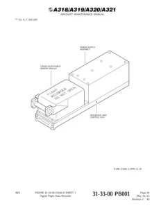
Reviews

There are no reviews yet.

Be the first to review “Airbus A318 A319 A320 A321 Aircraft Maintenance Manual Chapter 28 Fuel Rev 40 – 2012”

What Our Customers Say

★★★★★ Live reviews from customers
Loading customer reviews...
0
    0
    Your Cart
    Your cart is emptyReturn to Shop
    🛒
    Recently Purchased
    🕒 verified order