
Piper PA-32-301FT 6X and PA-32-301XTC 6XT Airplane Maintenance Manual 2003-2008
Original price was: $42.95.$26.95Current price is: $26.95.
Piper Aircraft Airplane Maintenance Manual P/N 766-854 for PA-32-301FT Piper 6X serials 3232001 thru 3232074 and PA-32-301XTC Piper 6XT serials 3255001 thru 3255051, covering 2003-2008 6X and 2003-2006 6XT airframes, Lycoming IO-540-K1G5 and TIO-540-AH1A powerplants, inspections, systems, and wiring.
Description
File Details
- Manual type: Airplane Maintenance Manual (Instructions for Continued Airworthiness)
- Brand / models: Piper PA-32-301FT Piper 6X and PA-32-301XTC Piper 6XT
- Language: English
- Page count: 1438
- File format: PDF
- Part number: 766-854
- Original publication: June 1, 2003 (ORG030601)
- This revision: PR090228, February 28, 2009
Which Airplanes This Book Serves
The Piper PA-32-301FT 6X and PA-32-301XTC 6XT Airplane Maintenance Manual 2003-2008 is the Piper Aircraft, Inc. maintenance publication prepared to GAMA Specification No. 2 chapter numbering. Effectivity is limited to PA-32-301FT serial numbers 3232001 thru 3232074 and PA-32-301XTC serial numbers 3255001 thru 3255051. Model-year tables in the introduction list 6X production from 2003 through 2008 and 6XT production from 2003 through 2006 as a general reference only; always match the airplane data plate to those serial ranges before using a procedure.
The manual itself is the Instructions for Continued Airworthiness required by FAR Part 23, Appendix G. Chapter 4 holds the FAA-approved Airworthiness Limitations section (4-00-00). Chapter 5 holds the inspection program (5-20-00) plus time limits, special inspections, and unscheduled checks. Instructions for Continued Airworthiness belonging to non-Piper approved STC installations are not in this book; any airplane modified that way must also be inspected to the STC holder’s ICA.
Powerplant, Propeller, Fuel, and Gear Particulars
Chart 1 in Chapter 6 records the hardware these airframes were built around. The PA-32-301FT (6X) uses a Lycoming IO-540-K1G5 rated 300 HP at sea level at 2700 RPM. The PA-32-301XTC (6XT) uses a turbocharged Lycoming TIO-540-AH1A rated 300 HP to 12,000 ft at 2500 RPM. Both share FAA Type Certificate 1E4, firing order 1-4-5-2-3-6, magneto timing of 20 degrees BTC, magneto point clearance of .010 ± .002, a Sky-Tec 149-24PM 28-volt starter, an Electrosystems 90-amp 28-volt alternator P/N 680-501, and an Electrosystems VR-320 voltage regulator P/N 694-020. Oil sump capacity is 12 U.S. quarts with 9.25 quarts usable. Specified fuel is aviation grade 100/100LL.
Magnetos differ by model: Slick 6351 (L/H) and 6350 (R/H) on the 6X; Slick 6361 (L/H) and 6360 (R/H) on the 6XT. Both airplanes use a three-blade Hartzell HC-I3YR-1RF / F7663DR propeller, 78 in. diameter (77 in. minimum). Low-pitch / high-pitch blade angles at the 30-inch station are 12.4° ± 0.2° and 32° ± 1° on the 6X, and 15.2° ± 0.2° and 34.0° ± 0.5° on the 6XT. Governors are Hartzell V-5-4 (6X) and V-5-6 (6XT).
Four fuel tanks (two interconnected cells in each wing) hold 53.5 U.S. gallons per wing, 107 gallons total onboard and 102 gallons usable. The electric fuel pump is a Weldon 28-volt unit P/N 461-750. Landing gear is fixed oleo (air-oil) using MIL-H-5606 in the struts and brakes. Wheel tread is 10 ft. 7 in., wheelbase 7 ft. 8 in., nose-wheel travel 30° ± 2° left and right. Nose and main tires are Type III 6.00 x 6, 8-ply Michelin Air, inflated to 35 psi nose and 55 psi main. Nose and main strut pressures under static load (empty weight plus full fuel and oil) are 225 ± 22.5 psi and 250 ± 25 psi.
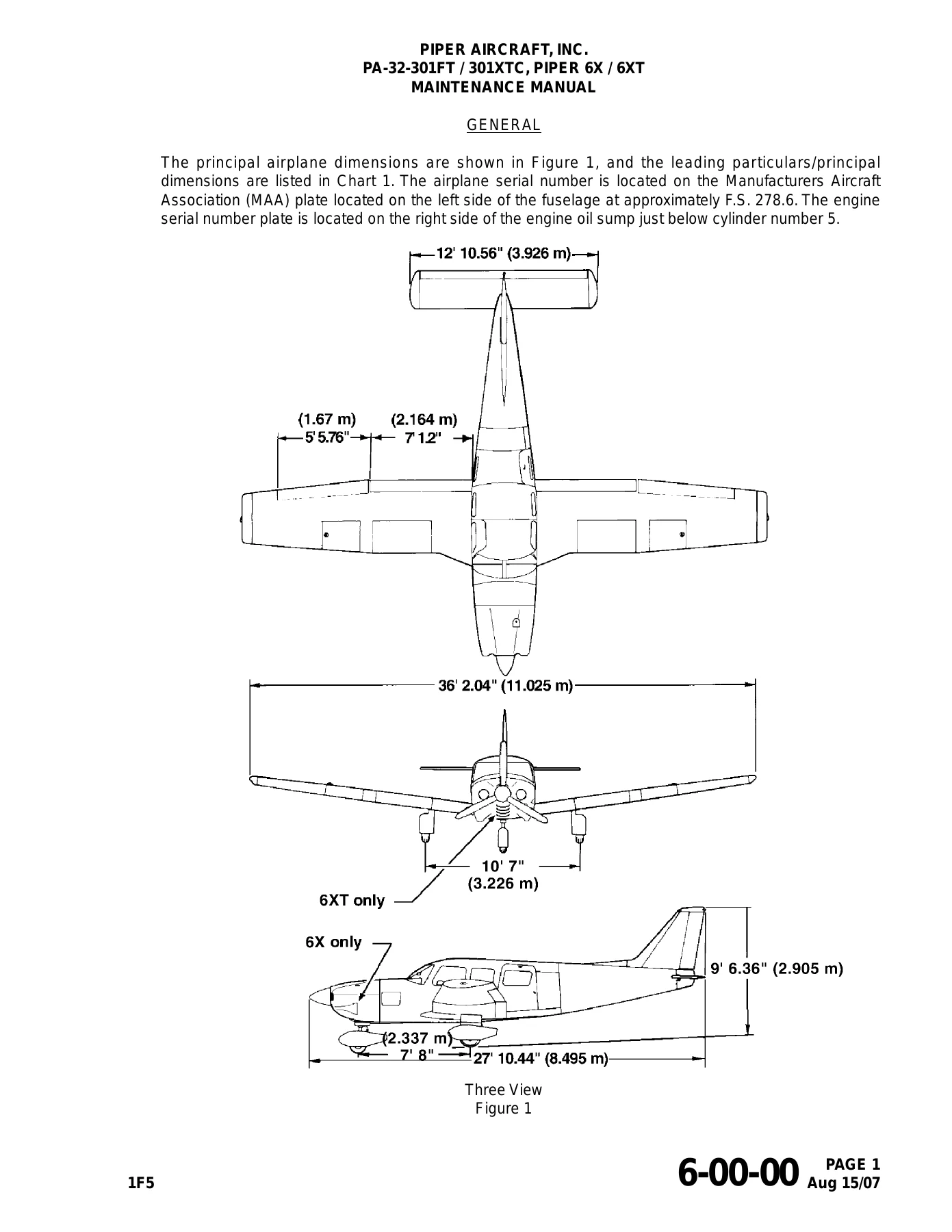
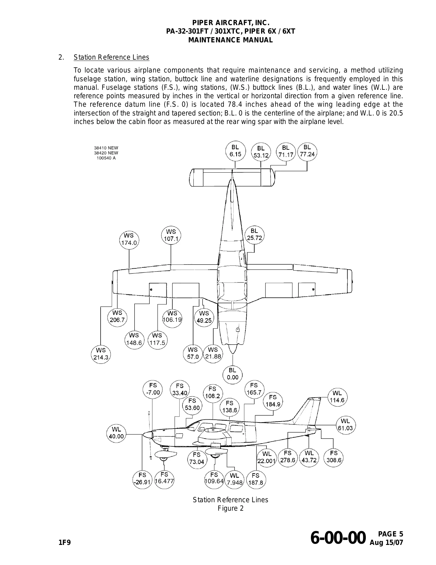
The three-view in Chapter 6 lists a wingspan of 36 ft 2.04 in. (11.025 m), overall length of 27 ft 10.44 in. (8.495 m), and height of 9 ft 6.36 in. (2.905 m). Station references start at a fuselage datum 78.4 inches ahead of the wing leading edge at the straight-to-taper intersection; buttock line 0 is the airplane centerline; water line 0 is 20.5 inches below the cabin floor at the rear wing spar with the airplane level.
Chapters Covered
- Chapter 4 Airworthiness Limitations — FAA-approved limitations
- Chapter 5 Time Limits / Maintenance Checks — general, time limits, scheduled maintenance, special inspections, unscheduled maintenance checks
- Chapter 6 Dimensions and Areas — leading particulars, station reference lines, access plates and panels
- Chapter 7 Lifting and Shoring — jacking
- Chapter 8 Leveling and Weighing — weighing and leveling
- Chapter 9 Towing and Taxiing
- Chapter 10 Parking and Mooring
- Chapter 11 Placards and Markings — exterior and interior
- Chapter 12 Servicing — replenishing and scheduled servicing
- Chapter 20 Standard Practices – Airframe — hardware, tubing, torque practice
- Chapter 21 Environmental Systems — distribution, heating, cooling / air conditioning
- Chapter 22 Auto Flight — S-TEC System 55X autopilot
- Chapter 23 Communications — audio integrating and static discharging
- Chapter 24 Electrical Power — DC generation, external power, load distribution
- Chapter 25 Equipment / Furnishings — flight compartment and emergency equipment
- Chapter 26 Fire Protection — portable extinguisher
- Chapter 27 Flight Controls — aileron and tab, rudder and tab, stabilator and tab, flaps
- Chapter 28 Fuel — storage, distribution, indicating
- Chapter 30 Ice and Rain Protection — airfoil TKS, pitot and static heat, propeller
- Chapter 31 Indicating / Recording Systems — central warning / annunciator
- Chapter 32 Landing Gear — main gear, nose gear, wheels and brakes
- Chapter 33 Lights — flight compartment and exterior
- Chapter 34 Navigation — pitot/static, Avidyne Entegra and Garmin 1000 EFIS, heading systems
- Chapter 35 Oxygen — crew / passenger system (6XT)
- Chapter 37 Vacuum — distribution and indicating
- Chapter 39 Electrical / Electronic Panels — instrument and control panels
- Chapter 51 Structures — investigation, cleanup, aerodynamic smoothness, repairs, electrical bonding
- Chapter 52 Doors — passenger/crew and cargo
- Chapter 53 Fuselage — main structure
- Chapter 55 Stabilizers — stabilator, vertical stabilizer, rudder
- Chapter 56 Windows — flight and passenger compartment
- Chapter 57 Wings — auxiliary structure, attach fittings, flight surfaces
- Chapter 61 Propellers — propeller assembly and controlling
- Chapter 70 Standard Practices – Engine
- Chapter 71 Power Plant — cowling and mounts
- Chapter 73 Engine Fuel and Control — distribution and controlling
- Chapter 74 Ignition — electrical supply, distribution, switching
- Chapter 76 Engine Controls — power control
- Chapter 77 Engine Indicating — power and temperature
- Chapter 78 Exhaust
- Chapter 79 Oil — distribution and indicating
- Chapter 80 Starting — cranking
- Chapter 81 Turbines — turbo-supercharger (6XT)
- Chapter 91 Charts and Wiring Diagrams — torque charts and electrical schematics
Taken together, those chapters give a technician the ICA package for the entire airplane: mandatory life limits, 50/100-hour and annual-style inspection tasking, ground handling, replenishment, structure and control-surface work, landing-gear overhaul practice, fuel-cell and selector-valve service, environmental and ice-protection systems, 28-volt electrical generation, both EFIS suites installed on these serials, Hartzell propeller and governor work, and airframe-side engine, ignition, oil, exhaust, and turbocharger tasks. Vendor publications listed in the introduction (Lycoming, Hartzell, Slick, Garmin, Avidyne, S-TEC, Weldon, Parker Hannifin, Artex, Scott Aviation, and others) are called out wherever a component must be serviced to the vendor manual rather than only to this book.
Inspection Program, Time Limits, and Ground Handling
Chapter 5 is the working inspection engine of the Piper PA-32-301FT 6X and PA-32-301XTC 6XT Airplane Maintenance Manual 2003-2008. It separates scheduled work from special and unscheduled checks and points back to Chapter 4 for FAA-approved replacement times and structural intervals. Periodic Inspection Reports P/N 766-857 / 766-858 and Progressive Inspection Manuals P/N 767-027 / 767-028 are identified as snapshots of those ICA sections, not stand-alone substitutes. Time-limit text also covers Hartzell propeller and governor overhaul windows (five or six years, or 2000 / 2400 hours per the latest Hartzell Service Letter No. 61), alternator overhaul, magneto 100- and 500-hour inspections, and oxygen-system recharge-valve replacement on the 6XT.
Chapters 7 through 12 walk jacking, weighing, leveling, towing, taxiing, parking, mooring, placard location, fuel and oil replenishing, oleo servicing with MIL-H-5606, tire service, and the lubrication chart. Access-plate maps and station diagrams in Chapter 6 tell the mechanic where to open the airplane without guessing.
Airframe Systems a Shop Will Actually Touch
Flight-control chapters give cable inspection technique, pulley wear patterns, aileron bellcrank installation, rudder and steering pedal assembly, rudder-trim geometry, stabilator travel stops, flap torque-tube and position-switch rigging, and static-balance limits after paint or repair. Fuel work covers inboard aluminum tanks, outboard bladder cells, seven-year tank/wing-spar corrosion inspection, locking caps, selector valve and nylon filter bowl (no field disassembly of the selector), Weldon pump inspection, dual quantity-gauge bench test, and wing sight gauges. Landing-gear text disassembles main and nose oleos, fairings, Cleveland 40-120C main and 40-56B / 40-30665 nose wheels, and Cleveland 30-83A brakes, including lining tolerance and disk minimum thickness.
Environmental coverage includes ram-air and overhead ventilation, cabin heat ducting, and the optional Sanden compressor / Enviro evaporator air-conditioning circuit with charging, leak, and evacuation setups. Ice protection covers heated pitot-static plumbing plus the optional TKS weeping-wing system: porous-panel cross-section, proportioning units, fluid tank and sender, filter, nylon tubing, propeller slinger ring and blade boots. Electrical generation describes the 90-amp Electrosystems alternator (exploded view and diode/stator tests), belt tension, 20-amp standby alternator on later EFIS airplanes, aft-fuselage battery, and overvoltage-relay checks. Vacuum pumps carry a vane-wear inspection port procedure. Structures, doors, fuselage, wings, windows, and empennage chapters cover skin repairs, thermoplastic patching, metal/wire stitching, electrical bonding millivolt-drop tests (including G1000 LRU grounds), wing-attach bolt practice, and control-surface balancing.
Avionics, Engine Installation, and Schematics
Chapter 22 documents the S-TEC System 55X rate-based autopilot: component locator, pitch/roll/trim servos, clutch-torque adjustment, and flap compensator. Chapter 34 is the large navigation chapter and treats both factory EFIS paths found on these serials — Avidyne Entegra (PFD, MFD, magnetometer/OAT) and Garmin 1000 (GDU 1040 displays, GMA 1347, GIA 63W, GEA 71, GTX 33, GDC 74A, GTP 59, GRS 77, GMU 44, GDL 69/69A) — including configuration-mode navigation, software load, magnetometer calibration, engine-page sensor checks, and lighting curves. Conventional pitot/static testing and the optional King KCS-55A flux-valve heading system are also here. Communications cover the GMA-340 audio panel functional test on non-G1000 airplanes. Chapter 91 supplies torque charts and the electrical schematics the troubleshooting tables keep pointing to.
Powerplant chapters stay on the airframe side of the firewall: cowling, engine mounts and shock mounts, removal/installation, throttle and mixture cable rigging, air-bleed fuel nozzles, Slick magneto timing to the 20° BTC marks, impulse-coupling inspection, ignition-harness repair, Sky-Tec starter service, oil distribution and indicating, exhaust, and — on the 6XT — turbocharger V-band coupling 100-hour inspection, wastegate clearance, and lockwire practice. Lycoming overhaul limits remain in the Lycoming manuals listed in the introduction (direct-drive overhaul P/N 60294-7, parts catalogs PC-615 / PC-615-12, operators handbooks 60297-10 / 60297-23).
Put This Manual to Work
With the Piper PA-32-301FT 6X and PA-32-301XTC 6XT Airplane Maintenance Manual 2003-2008 on the bench, a mechanic can run the ICA inspection program, service oleos and brakes to the printed pressures and extensions, rig aileron, rudder, stabilator, flap, and propeller-governor controls to the charted travels and tensions, time magnetos, inspect TKS panels and porous-media flow, load and check G1000 or Entegra LRUs, charge or leak-test air conditioning, and follow Chapter 91 schematics when an annunciator or bus fault appears. Using the values printed for this serial block — not a Saratoga, Cherokee Six, or later PA-32 — keeps cable tensions, blade angles, strut pressures, and fuel quantities on the airplane that is actually in the hangar.
Download is instant after purchase. The file opens on a computer, tablet, or phone, and pages can be printed for the job card or kept in the digital library. No printed volume ships and there is no waiting on back-order media.
Reviews
There are no reviews yet.