Description
Pratt & Whitney Canada PT6A Engine Overhaul Manual (Chapter 72, P/N 3013243)
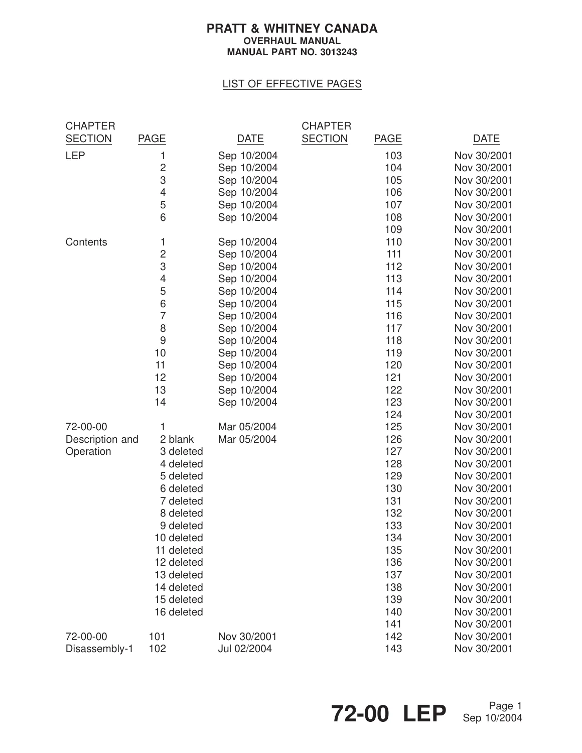
This is the Chapter 72 Overhaul Manual, Part No. 3013243, for the Pratt & Whitney Canada PT6A turboprop engine family, covering the PT6A-21, PT6A-27 and PT6A-28 variants. If you are looking for a genuine PT6A Engine Overhaul Manual that walks through the complete power section and gas generator teardown and rebuild, this Chapter 72 Overhaul Manual is built exactly for that job.
- Manual Type: Overhaul Manual
- Brand/Engine Family: Pratt & Whitney Canada PT6A (PT6A-21 / PT6A-27 / PT6A-28)
- Manual Part No.: 3013243
- Chapter: 72 – Engine
- Language: English
- Page Count: 388 pages
- File Format: PDF
- Latest Revision Date: Sep 10/2004
Complete PDF Bookmark Tree
Complete Bookmarks
The complete bookmarks in the “Pratt & Whitney Canada PT6A Engine Overhaul Manual – Chapter 72 (P/N 3013243)” are as follows:
Open First Pagep. 1
+ENGINE – DESCRIPTION AND OPERATIONp. 21
1. Description and Operationp. 21
2. Engine Specifications and Leading Particularsp. 21
3. Engine Stations, Flanges and Bearingsp. 21
+ENGINE – DISASSEMBLY-1: EXTERNAL COMPONENTSp. 23
1. Generalp. 23
2. Consumable Materialsp. 23
3. Special Toolsp. 24
4. Fixtures, Equipment and Supplier Toolsp. 24
+5. Preparation for Disassemblyp. 24
A. Generalp. 24
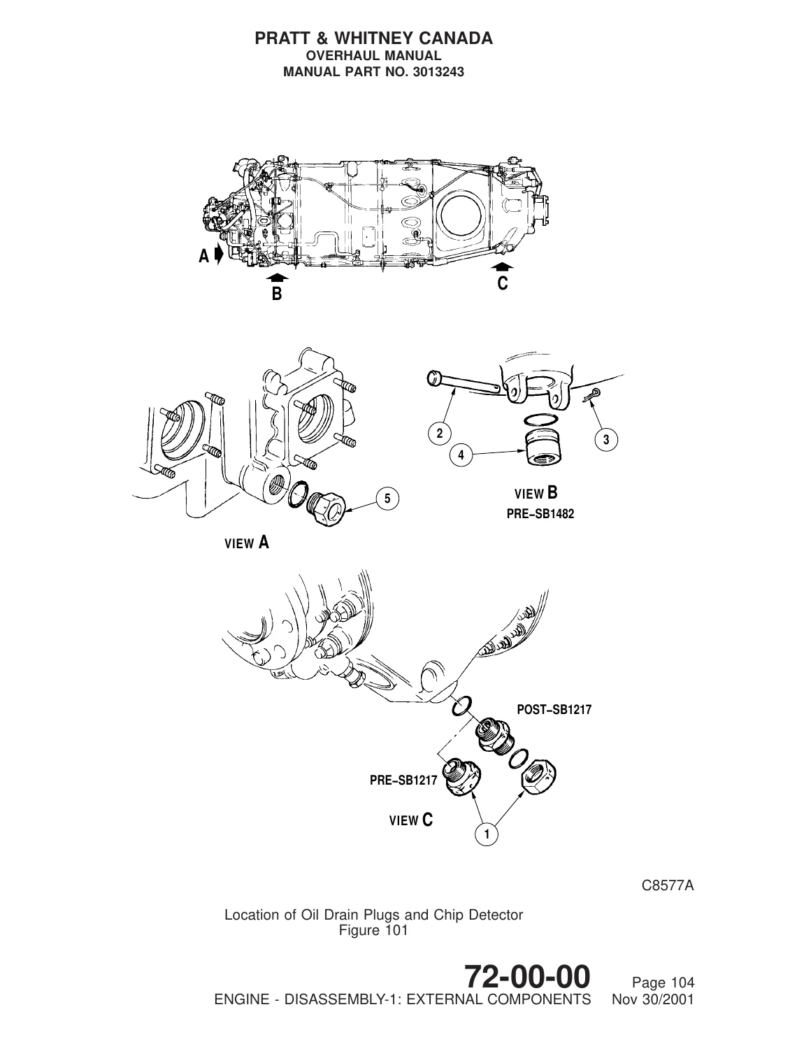
B. Draining Engine Oil Systemp. 24
+6. Removal of Externalsp. 24
A. Removal of Oil Transfer Tubesp. 24
B. No. 2 Bearing Scavenge Oil Tube Assemblyp. 25
C. External Scavenge Oil Tubesp. 25
D. Removal of Electrical Connector from Heated Pneumatic Linesp. 27
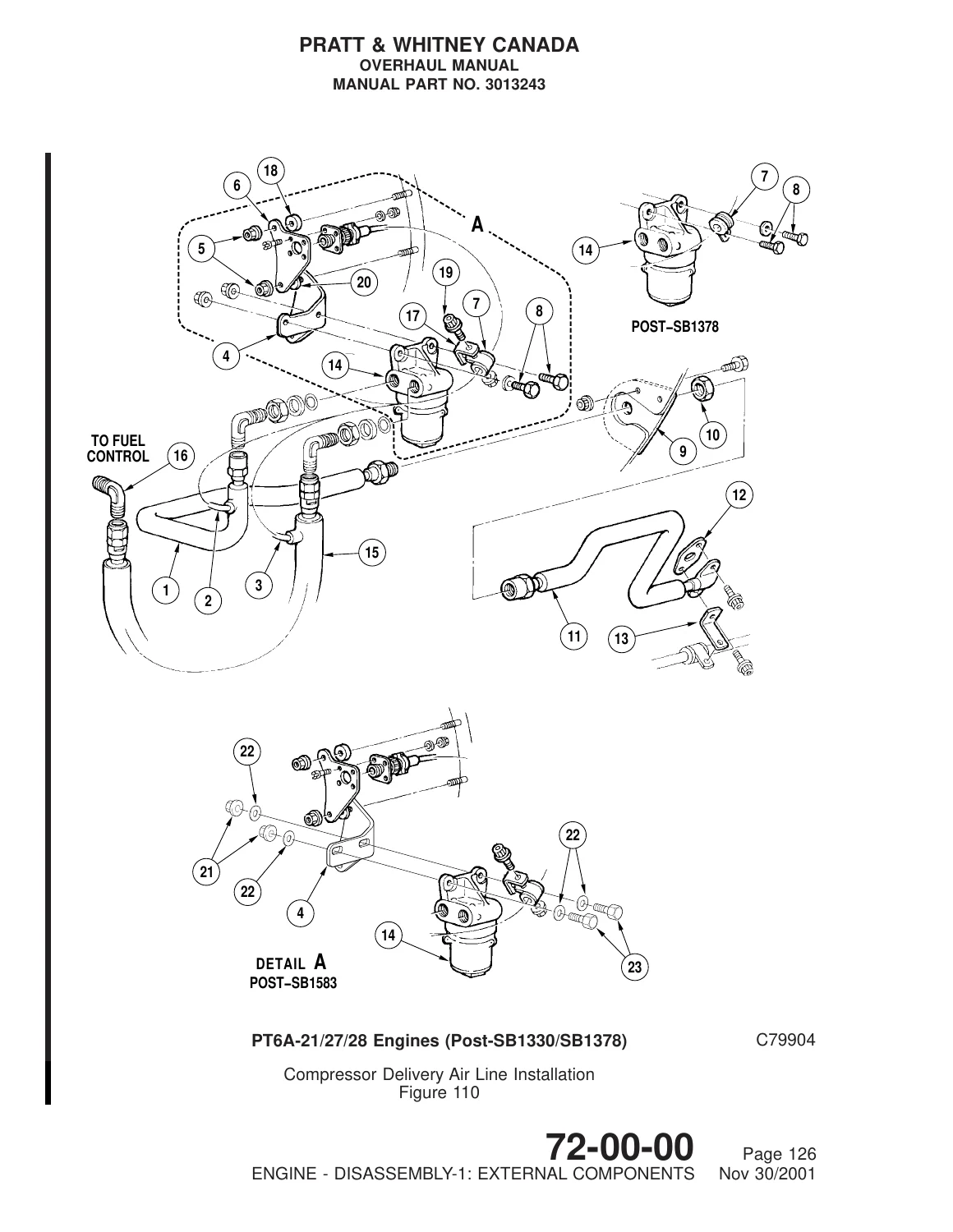
E. Compressor Delivery Air Line Installationsp. 29
F. Propeller Governor Pneumatic Tubesp. 46
G. Fuel Tubes and Flexible Hoses (PT6A-21 Engines)p. 47
H. Fuel Tubes and Flexible Hoses (PT6A-27/-28 Engines)p. 47
I. Ignition Cables (PT6A-21 Engines)p. 51
J. Ignition Cables (PT6A-27/-28 Engines)p. 59
K. Interconnect Linkage Group – Rearp. 65
L. Interconnect Linkage Group – Frontp. 65
M. Interconnect Linkage Group – Push-pull Controlp. 67
+ENGINE – DISASSEMBLY-2: ACCESSORY COMPONENTSp. 77
1. Generalp. 77
2. Consumable Materialsp. 78
3. Special Toolsp. 78
4. Fixtures, Equipment and Supplier Toolsp. 78
+5. Removal of Accessoriesp. 78
A. Remove Propeller Governorp. 78
B. Remove Oil-To-Fuel Heaterp. 78
C. Remove Check Valve (minimum pressurizing)p. 79
D. Remove FCU (PT6A-21 Engines)p. 79
E. Remove FCU (PT6A-27/28 Engines)p. 81
F. Remove Fuel Pumpp. 81
G. Remove Starting Control (Dual Line Fuel System)p. 81
H. Remove Oil Filter Elementp. 83
I. Oil Filter Housing Assemblyp. 85
J. Remove T5 Trim Wiring Harnessp. 87
K. Remove Ignition Regulatorp. 87
L. Remove Ignition Exciterp. 89
+ENGINE – DISASSEMBLY-3: MODULES AND MAJOR SUB-ASSEMBLIESp. 103
1. Generalp. 103
2. Consumable Materialsp. 104
3. Special Toolsp. 104
4. Fixtures, Equipment and Supplier Toolsp. 104
+5. Removal of Firesealsp. 104
A. Center Firesealsp. 104
B. Rear Fireseal (without wash ring)p. 104
C. Rear Fireseal and Compressor Wash Ringp. 105
+6. Separate Engine into Major Sub-Assembliesp. 105
A. Removal of Power Sectionp. 105
B. Removal of Accessory Gearboxp. 109
+7. Unscheduled Removal of Power Section from Gas Generator Assemblyp. 114
A. Install Engine in Stand (PWC30800)p. 114
+ENGINE – CLEANINGp. 119
1. Generalp. 119
2. Consumable Materialsp. 119
3. Special Toolsp. 120
4. Fixtures, Equipment and Supplier Toolsp. 120
+5. Cleaningp. 120
A. Generalp. 120
B. General Precautionsp. 120
C. Cleaning Precautionsp. 121
D. Corroded Magnesium Housingsp. 121
E. Oil Filter Cleaning and Inspectionp. 122
F. Cleaning P3 Air Filterp. 123
G. Vapor Honingp. 125
+ENGINE – INSPECTIONp. 127
1. Generalp. 127
2. Consumable Materialsp. 127
3. Special Toolsp. 127
4. Fixtures, Equipment and Supplier Toolsp. 127
5. Self-locking Fastenersp. 128
+6. Service Time Markingp. 129
A. Life Monitoring Methodsp. 129
B. Accumulation of Nos. 1 through 4 Bearing Hoursp. 129
+7. Tubes and Hosesp. 129
A. Standard Instructionsp. 129
+8. Antifriction Bearing Inspectionp. 132
A. Inspection Proceduresp. 132
B. Bearing Repairsp. 132
C. Aniti Friction Standard Proceduresp. 132
+9. Gears and Gearshaft Inspectionp. 133
A. Visual Inspection Of Gear Teethp. 133
B. Magnetic Particle Inspectp. 134
C. Inspect Carbon Seal Facep. 134
D. Inspect Splinesp. 134
E. Inspect Threadsp. 134
F. Inspect Retaining Ring Grooves and Slotsp. 135
G. Inspect Oil Hole(s)p. 135
H. Inspect Gearshaft Bearing Diametersp. 135
I. Inspect Remaining Surfacesp. 135
J. Inspect All Surfacesp. 136
+ENGINE – REPAIRp. 137
1. Generalp. 137
2. Consumable Materialsp. 137
3. Special Toolsp. 137
4. Fixtures, Equipment and Supplier Toolsp. 138
+5. Restoration of Protective Coatingp. 138
A. Stripping of Surface Sealant (Araldite) Coating from Magnesium Componentsp. 138
B. Application of Surface Sealant (Araldite) on Magnesium Componentsp. 138
C. Touch-up of Araldite Coated Componentsp. 139
6. General Proceduresp. 139
+7. Damaged Stud Holesp. 140
A. Repair Damaged Stud Holesp. 140
+8. Replacement of Helical Coil Insertp. 140
A. Replace Damaged Insertsp. 140
+9. Weld Repairp. 141
A. Welding Proceduresp. 141
B. Weld Repairsp. 141
+10. Loop Clampsp. 141
A. Replacement of Damaged Loop Clamp Grommetsp. 141
11. Copper Platingp. 141
+12. Stainless Steel Oil Tubesp. 143
A. Repair Oil Tubes With Dentsp. 143
B. Repair Oil Tubes With Damaged Ferrules Or Dentsp. 143
+FINAL ASSEMBLY – 1: ENGINE ASSEMBLYp. 147
1. Generalp. 147
2. Consumable Materialsp. 147
3. Special Toolsp. 147
4. Fixtures, Equipment and Supplier Toolsp. 147
+5. Assembly of Engine Major Sub-Assembliesp. 148
A. Installation of Accessory Gearbox Assembly to Gas Generator Assemblyp. 148
+6. Power Sectionp. 149
A. Installation of Power Section on Gas Generator Assemblyp. 149
+7. Installation of Firesealsp. 151
A. Center Firesealp. 151
B. Rear Fireseal and Compressor Wash Ring (if fitted)p. 157
C. Installation of Rear Fireseal and Compressor Wash Ringp. 157
+FINAL ASSEMBLY – 2: ACCESSORY AND EXTERNAL COMPONENTSp. 163
1. Generalp. 163
2. Consumable Materialsp. 163
3. Special Toolsp. 164
4. Fixtures, Equipment and Supplier Toolsp. 164
+5. Installation of Accessory Unitsp. 164
A. Oil Filter Element, Filter Housing and Check Valve Assemblyp. 164
B. Starting Control (PT6A-27/-28 Engines)p. 165
C. Fuel Pumpp. 165
D. Fuel Control Unit (PT6A-21 Engines)p. 169
E. Fuel Control Unit (PT6A-27/-28 Engines)p. 169
F. Oil-to-Fuel Heaterp. 171
G. Check Valve (Minimum Pressurizing)p. 171
H. Propeller Governorp. 173
I. Ignition Current Regulatorp. 175
J. Ignition Exciterp. 175
+6. Installation of Externalsp. 179
A. Fuel Delivery Tubes and Flexible Hoses (PT6A-21 Engines)p. 179
B. Fuel Delivery Tubes and Flexible Hoses (PT6A-27/-28 Engines)p. 181
C. Pressure Oil Transfer Tubesp. 186
D. No. 2 Bearing Scavenge Oil Tubep. 187
E. External Dual Scavenge Oil Tubesp. 191
F. Ignition Cables (PT6A-21 Engines)p. 194
G. Ignition Cables (PT6A-27/-28 Engines)p. 198
H. Propeller Interconnect Linkage Componentsp. 205
I. Propeller Governor Pneumatic Tubesp. 213
J. Compressor Delivery Air Linep. 219
K. Installation of Electrical Connector from Heated Pneumatic Tubep. 229
L. Pressure Test Pneumatic Tubesp. 239
M. T5 Trim Wiring Harnessp. 247
+7. Installation of Power Section to Gas Generator Casep. 248
+FINAL ASSEMBLY – 3: FINAL CHECKSp. 255
1. Generalp. 255
2. Consumable Materialsp. 255
3. Special Toolsp. 255
4. Fixtures, Equipment and Supplier Toolsp. 255
+5. Final Engine Checksp. 256
A. Generalp. 256
B. Checksp. 256
+ENGINE – FITS AND CLEARANCESp. 263
1. Generalp. 263
+2. Terms and Symbolsp. 263
A. Inspection Frequency Requirement (IFR)p. 263
B. Dimensional Checksp. 263
C. Torque Limitsp. 264
D. Index of Fits and Clearancesp. 264
+ENGINE – TESTINGp. 273
1. Generalp. 273
2. Consumable Materialsp. 273
3. Special Toolsp. 273
4. Fixtures, Equipment and Supplier Toolsp. 274
+5. Engine Test Equipmentp. 275
6. Engine Test Requirementsp. 275
7. Symbolsp. 276
+8. Preparation for Testp. 277
A. Engine/Propeller Controlsp. 277
B. Install Test Equipmentp. 277
C. Removal from Assembly Stand and Install in Propeller Test Standp. 279
D. Installation of Propellerp. 279
E. Remove from Assembly Stand and Install on Dynamometer Stand – (PWC32478) Mounting Arrangementp. 281
F. Install Engine on Dynamometer Stand – (PWC70326) Mounting Arrangementp. 281
G. Connect Test Stand Controlsp. 283
H. Connect Test Cell Plumbing and Instrumentationp. 283
I. Fill Engine Oil Tankp. 287
J. Depreserve Fuel Systemp. 289
+9. Engine Motoring, Starting and Shutdownp. 291
A. Prestart Checksp. 291
B. Wet Motoring Runp. 291
C. Dry Motoring Runp. 294
D. Engine Starting (PT6A-21)p. 294
E. Engine Starting (PT6A-27/-28)p. 295
F. Unsatisfactory Startp. 296
G. Shutdownp. 296
+10. Test Procedurep. 296
A. Points to be Understood before Testingp. 296
B. Supplementary Limitationsp. 297
C. Run-in Procedurep. 298
D. Preliminary Checksp. 298
E. AGB Vibration Surveyp. 300
F. Acceleration and Bodie Checksp. 301
G. Tt5 Trim Determinationp. 303
H. Acceptance Checksp. 305
I. Acceptance Valuesp. 305
+11. Control Settingp. 306
A. Minimum Governing Speedp. 306
B. Propeller Governor Maximum Speedp. 307
C. Underspeed Fuel Governing Checkp. 311
D. Maximum Ng Adjustmentp. 311
E. Minimum Fuel Flow Checkp. 312
+12. Post-test Run Checksp. 319
A. Checks To Confirm Engine Acceptability or Initiate Investigation Procedurep. 319
B. If Test Results are Acceptablep. 323
+13. Unusual Oil Conditionsp. 323
A. After Rectification for Unusual Oil Conditionsp. 323
14. Preservationp. 327
+15. Removal of Test Equipmentp. 327
A. Remove Test Plumbing and Instrumentationp. 327
+16. Install Engine in Assembly Standp. 330
A. Remove Engine From Propeller Test Stand And Install In Assembly Standp. 330
B. Remove Engine from Dynamometer Stand and Install in Assembly Standp. 330
17. Remove Test Accessoriesp. 330
18. Final Checkp. 330
+19. Power Section Run-inp. 331
A. Incremental Run-inp. 331
+ENGINE – TROUBLESHOOTINGp. 333
1. Generalp. 333
+2. Troubleshootingp. 333
A. Engine Problem Categoriesp. 333
+ENGINE – STORAGEp. 343
1. Generalp. 343
2. Consumable Materialsp. 343
3. Special Toolsp. 343
4. Fixtures, Equipment and Supplier Toolsp. 344
+5. Engine Storagep. 344
A. Fiberboard Shipping Container – Type Ip. 344
B. Fiberboard Shipping Container – Type IIp. 344
C. Fiberboard Shipping Container – Type IIIp. 345
D. Metal Storage and Shipping Containerp. 345
E. Humidity Controlp. 346
F. Re-activation of Desiccantp. 346
G. Storage of Enginep. 346
H. Stacking Engine Containers for Storagep. 347
+6. Installation of Engine in Overhaul Standp. 347
A. Engine Mounting Bracketsp. 347
B. Installation of Engine for Disassembly, Assembly and/or Testingp. 347
+7. Preservation/Depreservation of Enginep. 348
A. Depreservation of Enginep. 348
B. Preservation of Enginep. 351
C. Engine Fuel System Preservation (PT6A-21 Engines)p. 352
D. Engine Fuel System Preservation (PT6A-27/-28 Engines)p. 352
E. Engine Oil System Preservationp. 353
+8. Removal of Engine from Standp. 354
+9. Removal of Engine From Containerp. 354
A. Procedurep. 354
B. Removal of Engine from Type I Fiberboard Containerp. 355
C. Removal of Engine from Type II Fiberboard Containerp. 355
D. Removal of Engine from Type III Fiberboard (reinforced) Containerp. 360
E. Removal of Engine from Metal Containerp. 360
+10. Installation of Engine in Fiberboard Containerp. 363
A. Preparationp. 363
B. Installation of Engine in Type I Fiberboard Containerp. 363
C. Installation of Engine in Type II Fiberboard Containerp. 368
D. Installation of Engine in Type III Fiberboard (reinforced) Container :p. 370
+11. Installation of Engine in Metal Containerp. 371
+12. Renewal of Desiccant in Metal Containerp. 373
+ENGINE – LIGHT OVERHAULp. 377
1. Generalp. 377
+2. Light Overhaulp. 377
A. Conditions which Require Light Overhaulp. 377
+3. Light Overhaul Reference Guidep. 378
A. Generalp. 378
B. Engine Problems and Defectsp. 378
+4. Overtemperaturep. 379
+5. Dropped Enginep. 379
A. Procedurep. 379
B. Generalp. 383
+6. Unusual Oil Conditions – Generalp. 383
A. Generalp. 383
B. Metal Contaminantsp. 383
C. Particlesp. 383
D. Metal Chipp. 383
E. Examples Of Possible Contaminationp. 383
F. Unusual Oil Conditions (Part A)p. 383
G. Unusual Oil Conditions (Part B)p. 384
H. Rectify Part Ap. 384
I. Rectify Part Bp. 385
+7. Contamination by Fire Extinguishing Agentsp. 385
A. Generalp. 385
B. Engines Contaminated by Fire Extinguishing Agentsp. 385
C. Removal of Residual Deposits and Corrosion Repairp. 386
8. Power Sectionp. 386
+9. Engine Componentsp. 386
10. Accessoriesp. 387
+11. External Componentsp. 387
A. Problemsp. 387
B. Generalp. 387
12. Testingp. 388
Chapters Covered
- Engine – Description and Operation
- Engine – Disassembly-1: External Components (oil transfer tubes, pneumatic lines, fuel tubes and hoses, ignition cables, interconnect linkage)
- Engine – Disassembly-2: Accessory Components (propeller governor, oil-to-fuel heater, check valve, FCU, fuel pump, starting control, oil filter housing, T5 trim wiring harness, ignition regulator and exciter)
- Engine – Disassembly-3: Modules and Major Sub-Assemblies (fireseals, separation into power section and accessory gearbox)
- Engine – Cleaning (general precautions, corroded magnesium housings, oil filter cleaning, P3 air filter, vapor honing)
- Engine – Inspection (service time marking, tubes and hoses, antifriction bearing inspection, gear and gearshaft inspection)
- Engine – Repair (protective coating restoration, damaged stud holes, helical coil inserts, weld repair, loop clamps, copper plating, stainless steel oil tube repair)
- Final Assembly-1: Engine Assembly (major sub-assembly build-up, power section installation, fireseal installation)
- Final Assembly-2: Accessory and External Components (accessory unit and external tube/hose/cable installation)
- Final Assembly-3: Final Checks
- Engine – Fits and Clearances (dimensional checks, torque limits, index of fits and clearances)
- Engine – Testing (test equipment, engine motoring/starting, run-in procedure, acceptance checks and values, control setting)
- Engine – Storage Instructions
- Engine – Troubleshooting
- Engine – Light Overhaul
Together these sections give an overhaul technician the full, step-by-step path from receiving an engine off-wing through complete teardown, cleaning, inspection against wear limits, repair of common defects, rebuild, and acceptance testing on a dynamometer or propeller test stand.
Note: the Description and Operation, and Engine Specifications and Leading Particulars sections in this chapter direct the technician to the applicable PT6A Engine Maintenance Manual for that specific data; this Overhaul Manual chapter itself is focused on the disassembly, repair, assembly, fits/clearances and test procedures listed above.
Why Technicians Rely on This PT6A Overhaul Manual
This Pratt & Whitney Canada PT6A Engine Overhaul Manual gives you the documented procedures needed to correctly remove external and accessory components, separate the engine into its major sub-assemblies, clean and inspect parts against IFR (Inspection Frequency Requirement) ratings, repair magnesium housings and stud holes, and rebuild the engine with correct torque limits and fits/clearances. Following the exact sequences and torque values in this Chapter 72 Overhaul Manual reduces the risk of leaks, misassembly, or premature wear after overhaul, and the fits and clearances tables give you the same wear-limit data a certified overhaul shop would reference.
This PT6A-21 / PT6A-27 / PT6A-28 Overhaul Manual is delivered as an instant PDF download – no shipping, no waiting. Open it on a laptop, tablet or phone in the hangar or shop, or print out just the sections you need for the job at hand.
Reviews
There are no reviews yet.