
Radiometer ABL90 FLEX & FLEX PLUS Blood Gas Analyzer Service Manual 2022
Original price was: $39.95.$24.95Current price is: $24.95.
Complete Radiometer ABL90 FLEX and ABL90 FLEX PLUS service manual (202201 edition) covering troubleshooting, sensor and electronics checkout, complete software installation, replacement procedures, yearly service, service programs, module descriptions, spare parts, and PCB layouts for the 393-090 and 393-092 analyzers.
Description
Radiometer ABL90 FLEX & FLEX PLUS Service Manual — 2022 Edition
This is the Radiometer ABL90 FLEX & FLEX PLUS Blood Gas Analyzer Service Manual 2022, the full service documentation used by trained service personnel to maintain, troubleshoot, repair, and verify the ABL90 FLEX (393-090) and ABL90 FLEX PLUS (393-092) analyzers. Manual version 202201, identification number 994-667. It covers both the manual-inlet ABL90 FLEX and the auto-inlet ABL90 FLEX PLUS, including the Urea/Crea-configured FLEX PLUS variants.
File Details
- Manual type: Service Manual
- Brand: Radiometer (Radiometer Medical ApS)
- Models covered: ABL90 FLEX (393-090), ABL90 FLEX PLUS (393-092)
- Language: English
- Edition / version: 202201
- Identification number: 994-667
- Original date of publication: December 2009
- Current edition: 202201
- File format: PDF
Chapters Covered
- 1 Introduction — Disclaimer, Service policy, Test equipment and tools, Installation ID
- 2 Troubleshooting — Messages (numbers 1 through 1574), Status codes
- 3 Checkout and setup — Sensors and electronics (Sensor channels check, PO2 complete test, OXI complete test, Temperature check, Liquid sensor check, Enhanced clot detection, QC7+ support, FLEX PLUS Urea/Crea configuration), Software (Malware protection, Advanced configuration, USB flash drive handling, RMED AV Scan Tool, Complete software installation, Application software re-installation/upgrade, Remote software upgrade for RWIN10/RWES7/RXPE, Bootable USB flash drives, BIOS update, Upgrade to RWIN10 and V3.5), Miscellaneous (Electrical safety test, Service dump, Installation)
- 4 Replacement — Sensor module assembly, Inlet System, OXI module, Actuator unit, CPU and printer, Display, Sample mixer unit, Power supply and battery unit
- 5 Periodic service — Yearly service procedure
- 6 Service programs — Entry to service programs, Analyzing unit service, Sensors, Consumables, Oxi and pO2, Temperature, Fluid transport, Chip information, Miscellaneous, Other service programs (Software, Internal remote support, External remote support, LIVE Connect Data)
- 7 Module description — Mechanical and optical units, Inlet system, Wet section, Sensor module, Actuator unit, OXI module, Sample mixer unit, Electronics, Block Diagram, CPU unit, Inlet position detector PCB, Wet section control PCB, Sensor interface PCB, Sample mixer PCB, Bottom heat and LS interface PCB, Solution pack id and analyzer id PCBs, Manifold detector PCB, Hemolyzer PCB, Spectrometer PCB, Power supply, Printer unit, Battery option
- 8 Spare parts — Mounting base, Inlet system, Sensor module, Oximetry system, Actuator unit, Sample mixer unit
- 9 Drawings and Test Sheets — PCB layouts, Electrical safety test sheet
- 10 Appendices — Troubleshooting guide, Change history, Date of issue
What This Manual Gives the Service Technician
The ABL90 FLEX and FLEX PLUS are compact, cartridge-based blood gas analyzers that depend on precise fluid transport, thermostatted sensor cassettes, an OXI optical measurement system, and a wet section that must be kept clean and properly calibrated. This service manual supports the full service lifecycle of both analyzer models. It gives the technician the exact numeric service actions tied to each analyzer message number — covering calibration errors, drift out of range, sensitivity faults, liquid sensor calibration failures, OXI spectrum mismatch, tHb calibration problems, inhomogeneous rinse and calibration solutions, pump calibration errors, leak detection messages, temperature out-of-range conditions, and the many status codes that can appear at boot.
The checkout and setup chapter is where most day-to-day service happens: the Sensor Channels Check using the 903-603 Sensor Simulator, the pO2 Complete Test, the OXI Complete Test, the Temperature check, the Liquid Sensor check, and the procedures for enabling enhanced clot detection, enabling QC7+ support, and reconfiguring an ABL90 FLEX PLUS to support or remove the cUrea and cCrea parameters. The software chapter covers malware protection, USB flash drive handling, the RMED AV Scan Tool (with 933-929 and 933-891 tool versions), complete software installation for RXPE, RWES7 and RWIN10, application software re-installation and upgrade, remote software upgrade procedures for each operating system, creation of bootable USB flash drives, BIOS Update Tool V6, and the upgrade path to RWIN10 and V3.5.
For hardware work, the replacement chapter walks through removing and reinstalling the Sensor Module Assembly, the Actuator Unit, the OXI Module, the Sensor Cassette Bay Unit, the Sensor Interface PCB, the Open/Close motor, the Inlet Position Detector PCB, the Motion Mechanism and Inlet Coupler (393-092), the Inlet Probe, the Hemolyzer Unit, the Spectrometer Unit, the Analyzer ID PCB, the Solution Pack ID PCB, the Pump Rotor, the Waste Tube and Waste Connector, the Flow Selector PCB, the Actuator Motor and Actuator Rod, the CPU Unit, the Printer Unit, the Display and Touch-Screen, the Sample Mixer Unit, the Power Supply and the Battery Unit. Each procedure includes the torque values, alignment checks, lubrication points (Molykote PG75), and post-service verification steps where the manual specifies them.
Service Programs and Diagnostics
The service programs chapter documents every function available from the service menu: the Sensors program (with impedance measurement and the accepted MOhm ranges for pH, Na, pCO2, Ca, K and Cl), the Consumables program (open/close sensor bay, eject/prepare/lock solution pack, close valve), the Oxi / pO2 program (Read Spectrometer EEPROM, Oxi complete test, pO2 complete test, Update hemolyzer status, Hemolyzer On), the Temperature program (top, bottom, substrate, hemolyzer and barometer temperature with power), the Fluid transport program (Adjust manifold, Perform pressure test, Liquid Sensor Adjust, Pump Calibration, Solution Pack Check, Visual Flow Check, Clot detect/remove), the Chip information program for the three ID chips, and the Miscellaneous program (battery status, Sensor Simulator Test, Auto Inlet Control positions on 393-092). The Internal and External remote support screens and the LIVE Connect Data (IoT Gateway) configuration are also covered.
Reference and Reference Data
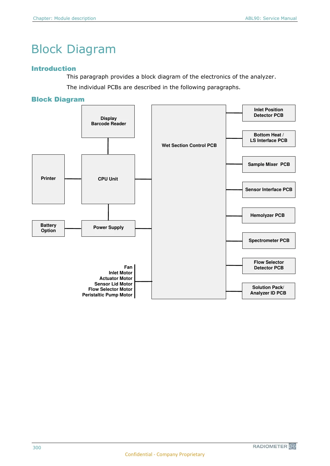
The module description chapter explains how each subsystem works, with block diagrams for the CPU Unit, Wet Section Control PCB, Sensor Interface PCB, Sample Mixer PCB, Bottom Heat / LS Interface PCB, Solution Pack and Analyzer ID PCBs, Manifold Detector PCB, Hemolyzer PCB and Spectrometer PCB. It documents the OXI initialization behaviour (the 200×200 Tikhonov correction matrix that must be re-established after replacing the Wet Section Control PCB or Spectrometer, which can take up to 60 minutes), the pO2 optical measurement principle, the hemolyzer 30 kHz cavitation process, the liquid sensor calibration principle, and the leak-current test circuit that underlies the "Leak current in analyzer detected" and "Leak current in relation to solution pack detected" messages.
Drawings, Spare Parts and Periodic Service
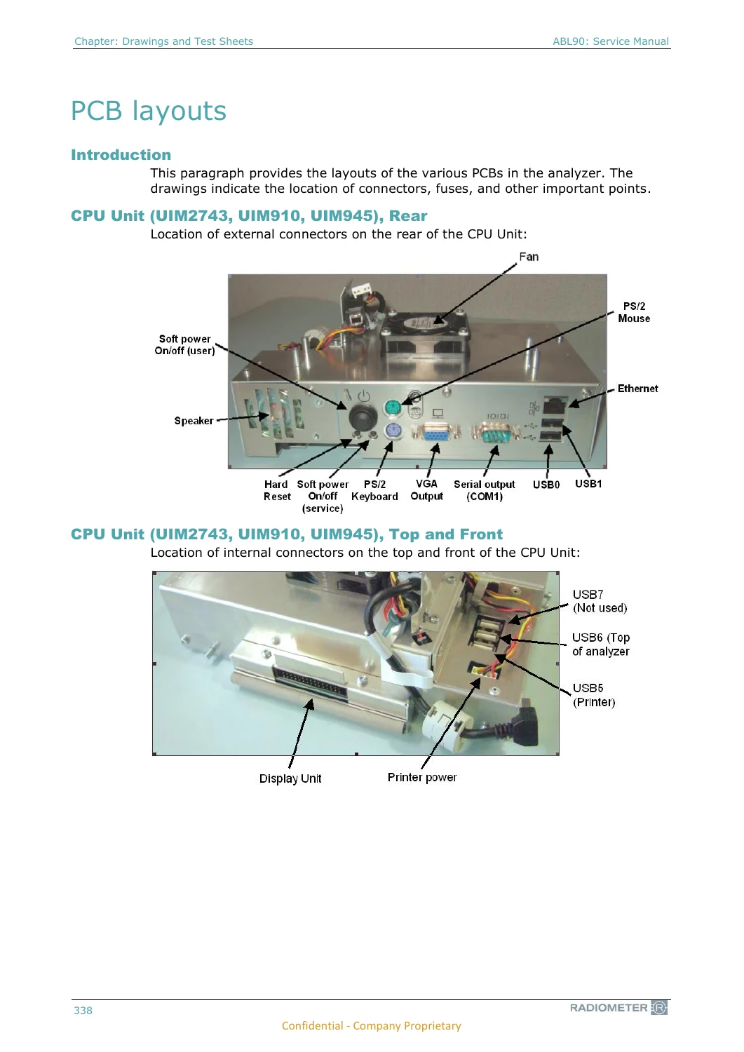
The spare parts chapter lists every field-replaceable part with its item number, including the module-level assemblies, PCBs, cables, fuses, motors, contact probes, gaskets, tubing, and consumable service parts. The drawings chapter provides PCB layouts for the CPU Unit (UIM2743, UIM910, UIM945 and E3800), Display Unit, Barcode Reader, Wet Section Control PCB, Sensor Interface PCB, Bottom Heat / LS Interface PCB, Solution Pack and Analyzer ID PCBs, Sample Mixer Unit and Flow Selector Detector PCB. The yearly service procedure is written as a complete step-by-step periodic maintenance flow with the Yearly Service Kit (905-899 for FLEX, 905-972 for FLEX PLUS) and the required disinfection and calibration materials.
Why This Manual Matters
On a blood gas analyzer, a wrong sensor channel, a misaligned contact probe array, a clogged waste tube or an out-of-tolerance calibration can silently affect patient results. The ABL90 service manual is built around the analyzer’s own message and status code system, so the technician can go from an error number to the exact service action without guesswork. It shows the accepted ranges, the calibration factors, the impedance limits, the pressure and vacuum targets, the torque values, and the post-replacement verification steps that tell you whether the analyzer is genuinely ready to return to clinical use.
IMAGES PREVIEW
Instant PDF Delivery
Delivered as an instant PDF download after payment. No shipping, no waiting for a physical book. Read it on a laptop, tablet or phone in the lab or at the bench, print the sections you need, and keep the full manual on hand for every ABL90 FLEX or ABL90 FLEX PLUS service visit. Whether you are replacing a Sensor Interface PCB, running an OXI Complete Test, configuring Urea/Crea on a FLEX PLUS, performing the yearly service, or working through a calibration drift message, this is the reference document that matches the analyzer on your bench.
Reviews
There are no reviews yet.