
Renault K-Series Truck Wiring Diagram Manual 2025 | 337017/29 | Complete Electrical Schematics PDF
Original price was: $74.95.$49.95Current price is: $49.95.
Complete 728-page Renault K-series truck wiring diagram manual, document 337017/29, covering Euro III, Euro V, Euro VI and Euro VI Step-E platforms. Includes CAN and LIN bus architecture, shared function schematics, equipment locations, harness routing, connector pinouts and fuse/relay tables.
Description
Renault K-Series Wiring Diagram Manual – Document 337017/29 (2025)
This is the complete electrical wiring diagram manual for Renault K-series trucks, published under document number 337017/29 in 2025. At 728 pages, it is a full-depth electrical reference covering communication bus architecture, shared function schematics, component locations, harness routing, connector pinouts and electrical distribution for Euro III, Euro V, Euro VI and Euro VI Step-E configurations.
Whether you are diagnosing a CAN bus fault, tracing a LIN bus signal, repairing a chassis harness, or verifying fuse and relay assignments, this manual provides the exact diagrams and tables the workshop needs.
File Details
- Manual type: Wiring Diagram Manual
- Brand: Renault Trucks
- Model: K-series
- Document number: 337017/29
- Year: 2025
- Language: English
- Page count: 728
- File format: PDF
Chapters Covered
- Communication Bus Architecture
- Shared Functions
- Wiring Diagrams
- Equipment Locations
- Layout of Controls
- Electrical Distribution
- Chassis – Cab/Bulkhead Grommet Connection
- Trailer Connections
- Available Power Supplies
- Wiring Harnesses
- Cab Inter-connectors
- Chassis Inter-connectors
Communication Bus Architecture
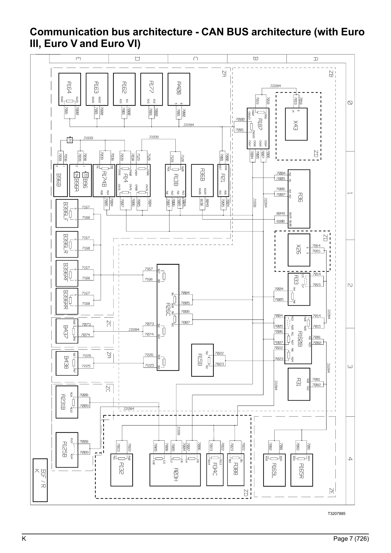
The manual opens with a full breakdown of the vehicle’s communication networks. It documents the LIN BUS architecture and the CAN BUS architecture across Euro III, Euro V, Euro VI and Euro VI Step-E with ECM 4.0. Device keys list every ECU, sensor and control unit on each bus segment, including the instrument cluster, engine ECM, EBS, transmission control, door modules, alarm, tachograph and telematics gateway. This section is essential for diagnosing communication faults, identifying bus termination points and understanding how each module talks to the others.
Shared Functions
The shared functions chapter groups the vehicle’s major electrical systems into clear, self-contained schematics. Each shared function includes its own key to devices with component codes, descriptions and grid locations. Systems covered include:
- Distribution and management of electrical power (with and without ADR)
- Euro III, Euro V, Euro VI and Euro VI Step-E anti-pollution systems
- Air production management
- Mechanical suspension
- Windscreen wiper and washer
- Electric rear-view mirrors
- Display and instrumentation
- Braking management (front, rear, controlled axle and trailer)
- Engine management (11-litre and 13-litre, all emissions standards)
- Driveline and differential lock management
- Automated manual transmission management
- Retarder
- Tachograph
- Windows and sunroof
- Interior and exterior lighting
- Locking and unlocking of doors
- Alarm and immobiliser
- Safety and driving assistance
- Air conditioning
These schematics show the main equipotentials of each system, the communication buses involved and the equipment that affects the function. They serve as the top-level overview before diving into the detailed wiring diagrams.
Wiring Diagrams
The core of the manual is a comprehensive set of wiring diagrams covering every electrical circuit on the vehicle. Each diagram is referenced by a sheet code and page number, making navigation straightforward. The diagrams are organised by system and include:
- Energy production – standard and ADR equipment
- Electrical distribution – standard on chassis
- Vehicle starting
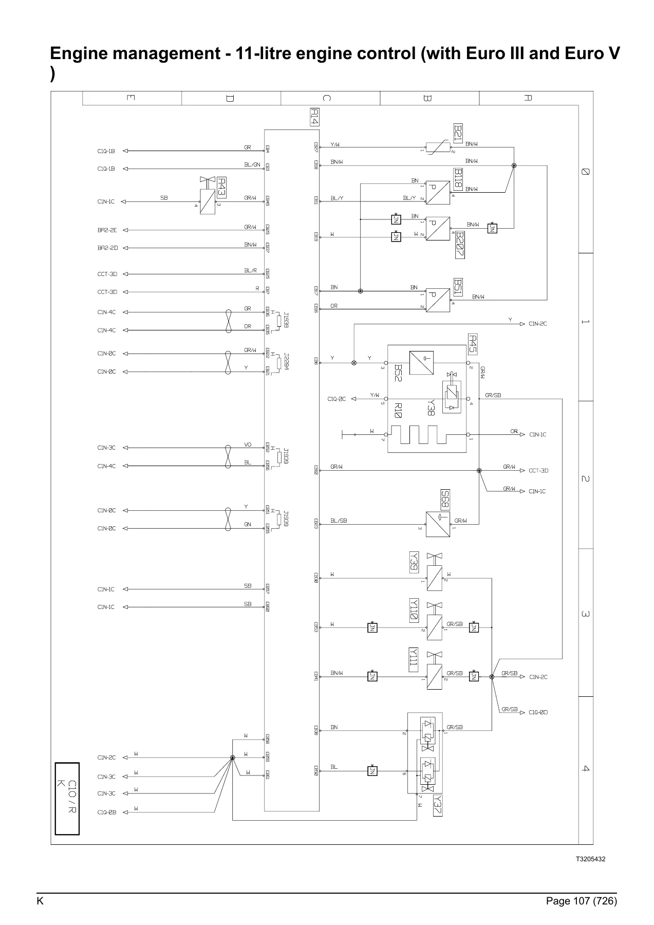
- Engine management – 11-litre and 13-litre, Euro III, Euro V, Euro VI and Euro VI Step-E, including injection control, urea supply and interface between engine and vehicle
- Vehicle management – main ECU, main information display, tachograph, fleet management, telematics and Era-Glonass
- Gearbox management – automated manual transmission
- Driveline management – differential lock and transfer box
- Retarder management
- Braking management – EBS, front and rear modules, brake pad wear sensors, trailer EBS
- Tyre pressure monitoring
- Suspension management
- Power-assisted steering
- Air production
- Safety management – immobiliser, door management, alarm, camera monitoring, airbag and alcotest
- Lighting and signalling – headlamps, rear lights, side parking lights, roof-mounted parking lights, horn
- Washing and wiping of windows
- Driving assist – front radar and side radars
- Life on board – cab compartment lighting, independent heating, air conditioning, heated seats, windscreen de-icing, sunroof, entertainment module and accessories
- Vehicle maintenance – cab tilt
- Trailer connections – rigid and tractor sockets
- Body builder system management – pre-equipment ECU, main ECU, central chassis ECU, electrical distribution box, supplementary lighting and BBIOM
Each diagram includes wire colours, pin numbers, connector references and component codes, allowing precise tracing of circuits from the battery to the load and back to earth.
Equipment Locations
This section provides a full summary of equipment locations with page references. It covers the distribution box, main information display (short and long dashboard), tachograph, electronic management of 11-litre and 13-litre engines across all emissions standards, fuel management, urea supply, vehicle management, power-assisted steering, energy production, air production, gearbox management, retarder, braking management, suspension, tyre management, differential lock, driveline management, vehicle maintenance connectors, power take-off, door management, safety systems, bodywork pre-equipment, life on board systems, driving assist, video surveillance, interior and exterior lighting, horn, washing and wiping, and earth points. This makes it fast to locate a component on the vehicle before beginning work.
Layout of Controls
The layout of switches on the dashboard and overhead ledge is documented with clear illustrations and component codes. This helps identify the function of every switch, its location and its associated diagram page.
Electrical Distribution
This chapter contains the complete fuse and relay tables for the electrical distribution box, including fuse ratings, circuit descriptions and diagram page references. It also covers fuses and relays outside the distribution box, the face A and face B connector pinouts of the distribution box, and the power supplies available inside the cab and on the chassis. This is the go-to reference for any electrical fault diagnosis.
Chassis – Cab/Bulkhead Grommet Connection
Detailed pinout tables for the connectors that pass through the cab/bulkhead grommet, including XC201 through XC213. Each pin is listed with its designation, polarity number and diagram page reference, making it easy to test circuits at the bulkhead.
Trailer Connections
Pinout tables for the EBS 7-pin trailer socket, EBS 15-pin trailer socket and trailer connections (7-pin type 24 N and 24 S). Each pin is described with its function and diagram page reference.
Available Power Supplies
This section lists all available power supplies inside the cab and on the chassis, with connector markings, ratings and locations. It includes the available power supplies at the body builder pre-equipment connectors (BBEC1A, BBEC2A, BBEC3A) and on the chassis (BB1, BB2, BB3). This is essential for anyone adding auxiliary equipment or body builder systems.
Wiring Harnesses
A complete summary of harness routings with connector codes, colours and pin counts. It covers the electrical distribution wiring harness, main CAN bus harness (J1939), body builder pre-equipment management harness, information display harness, tachograph harness, engine harnesses for 11-litre and 13-litre engines across all emissions standards, urea supply system harnesses, telematics, Era-Glonass, automated manual transmission, driveline management, EBS, door harness, alarm, camera monitoring, air conditioning, audio system, accessories, windscreen de-icing, driving assist, cab tilt, interior and exterior lighting, working lamps, wiper and washer, controls and side radars. Each entry lists the connector colour and pin count, helping technicians identify the correct harness before ordering or repairing.
Cab Inter-connectors
Detailed pinout tables for all cab inter-connectors, including BBEC1A, BBEC2A, BBEC3A, BBEC4, XC123, XC130_long, XC130_short, XC151, XC156, XC159, XC161, XC163_1, XC164_1, XC164_2, XC167, XC168, XC168_2, XC169, XC170_2, XC174_2, XC175, XC176, XC177, XC178, XC180_2, XC182, XC183, XC184, XC186_2, XC189, XC191, XC193, XC194_A, XC198_A, XC219, XC325, XC326, XC327, XC335, XC336, XC337, XC404, XC405, XC414, XC417, XC418, XC421, XC422, XC437, XC439, XC440, XC441, XC446, XC456, XC468 and Crew CAB. Each pin is listed with its designation, polarity number and diagram page reference.
Chassis Inter-connectors
Detailed pinout tables for all chassis inter-connectors, including XC301, XC302 (Euro III, Euro V and Euro VI), XC303 (automated manual transmission – Euro III, Euro V and Euro VI), XC311B, XC311C, XC312 (Euro III, Euro V and Euro VI), XC313, XC314, XC315, XC316 (Euro III, Euro V, Euro VI and Euro VI Step-E), XC317, XC318A, XC318C, XC319, XC320, XC321, XC322, XC323, XC326, XC328, XC330_2, XC331_2, XC332, XC334, XC336, XC342, XC346, XC347, XC348, XC351, XC357, XC358, XC359, XC360, XC361, XC416 and XT65. Each pin is listed with its designation, polarity number and diagram page reference.
Why This Wiring Diagram Manual Matters
Electrical faults on modern commercial trucks can be time-consuming and expensive to diagnose without the correct reference. This manual gives you the exact circuit paths, connector pinouts, wire colours, fuse ratings and component locations for the Renault K-series across all major emissions variants. It supports:
- Tracing short circuits, open circuits and high-resistance faults
- Diagnosing CAN and LIN bus communication errors
- Repairing or replacing chassis, cab and engine harnesses
- Adding body builder equipment and auxiliary power supplies
- Verifying fuse and relay assignments
- Understanding how each ECU communicates with the rest of the vehicle
- Locating components quickly using the equipment location section
- Testing circuits at the bulkhead, trailer socket and inter-connectors
With 728 pages of diagrams, tables and pinouts, this is the most complete electrical reference available for the Renault K-series. It covers Euro III, Euro V, Euro VI and Euro VI Step-E, making it suitable for a wide range of vehicle ages and configurations.
IMAGES PREVIEW
Instant PDF Delivery
This Renault K-series wiring diagram manual is delivered as an instant PDF download. There is no shipping, no waiting for a physical book and no risk of a damaged or lost parcel. The file can be viewed on any device – laptop, tablet or smartphone – and relevant pages can be printed for use in the workshop. Whether you are a fleet workshop, an independent garage, a mobile technician or a body builder, this manual puts the complete electrical system of the Renault K-series at your fingertips.
Reviews
There are no reviews yet.