
Renault Mascott DCI Electrical Workshop Manual 2003 (70 127) – Wiring Diagrams, Fuses & Relays PDF
Original price was: $59.95.$34.95Current price is: $34.95.
The complete Renault Trucks electrical workshop manual for the Mascott DCI range, document 70 127 from March 2003. 262 pages of wiring diagrams, appliance locations, fuse and relay tables, instrument panel data and earth points covering 110/130/140/150 common rail and mechanical fuel-injection variants.
Description
Renault Mascott DCI Electrical Workshop Manual – Document 70 127
This Renault Trucks electrical workshop manual covers the Mascott DCI range and documents the complete vehicle electrical equipment for both the 110/130/140/150 common rail fuel-injection and the mechanical fuel-injection variants. Published under document number 70 127 in March 2003, it is arranged by electrical function so each circuit can be traced from power supply through fuse, relay, appliance and earth without jumping between disconnected sections. This is the manual technicians use when diagnosing a no-start, a charging fault, an instrument panel warning, an ABS issue, a lighting problem or a trailer socket wiring query on Mascott DCI trucks.
File Details
- Manual type: Electrical workshop manual
- Brand: Renault Trucks
- Model: Mascott DCI
- Document number: 70 127
- Edition date: 03.2003
- Language: English
- Page count: 262
- File format: PDF
Chapters Covered
- A – Generalities
- B – Key to appliances
- C – Electrical diagram
- D – Location of appliances
- E – Fuses
- F – Relays
- G – Instrument panel
- H – Available power supplies
- I – Trailer socket
- J – Location of earths
Generalities, Colour Codes and Diagram Symbols
The opening chapter explains the colour-coding system used throughout the Mascott DCI wiring diagrams. Wire and connector colours are listed in full: BA White, JA Yellow, RG Red, BE Blue, MA Brown, SA Salmon, BJ Beige, NO Black, VE Green, CY Crystal, OR Orange, VI Violet and GR Grey. Four basic colours identify wire equipotentials across the harness: Red for +12 Volts before ignition, Yellow for +12 Volts after-ignition, Blue for lighting and signalling, and Black for earth. The generalities chapter also introduces the codification system used to identify electrical units without text inside the diagrams, the five unit types (appliances, hook-up connectors, instrument panels, earths and connecting units), and the symbol table that decodes every drawing used in the electrical plates.
Key to Appliances and Component Identification
Chapter B is the master index of every electrical unit on the Mascott DCI, listed in alphanumeric order with its item number, assignment and the electrical diagram plate on which it appears. Typical entries include the alternator (103 FA1, 103 FBA, 103 FBB), battery set (107 BA, 107 FA1, 107 FAB), starter (163 FA1, 163 FBA), COMMON RAIL ECU connectors (120 FAA, 120 FBA), ABS ECU and solenoid valves (118 FAA, 118 FAB), engine immobilizer coded stop solenoid valve (160 FAA), instrument panels with and without tachograph (247 FFA, 247 FEA, 247 FEB, 247 FEC), lighting rotary switch (209 AA), windscreen wiper motor (212 BA), fast idling control (903 FDA), cruise control (903 FDB), power take-off controls (903 FEA, 903 FEB), air conditioning compressor (171 FAA), heated seats (495 AA, 496 AA) and the radio-frequency central locking box (503 AA, 503 AB). Separate keys cover hook-up connectors (R3, R4, R11, R34, R107, R233 and others), instrument panel warning lamps (T01 to T35) and earth points (M2 to M16).
Electrical Diagrams – Complete Vehicle Circuit Coverage
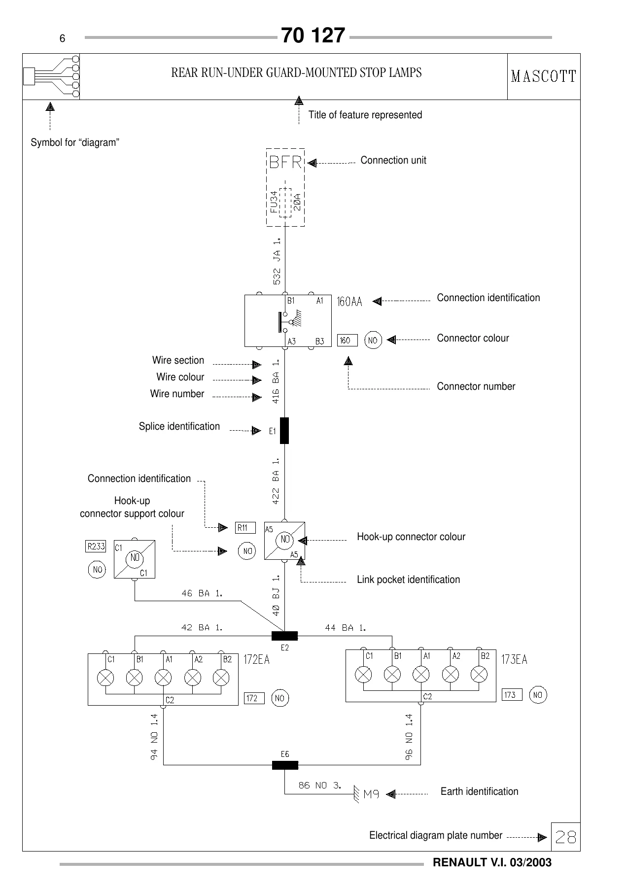
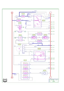
Chapter C contains the main electrical diagram plates, numbered from plate 1 through to plate 181, split by function. Plates cover the connection unit BFR (both common rail and mechanical fuel-injection), connection unit BIM, after-ignition power supply, power supply and starting, engine immobilizer and radio-frequency central locking, cab COMMON RAIL ECU (with and without options), engine COMMON RAIL ECU, fast idling and cruise control, FLAMMSTART cold starting device, fuel filter preheater, fuel filter water presence and clogging, declutching fan, cab heating and cab heating with air conditioning, run-under guard-mounted parking and fog lamps, van parking and fog lamps, main beam headlamps, headlamps adjustment, run-under guard-mounted flashing lamps, van flashing lamps, stop lamps, reversing lamps and reversing buzzer, roof lamps, van marker lamps, cab interior lighting, crew cab and van interior lighting, windscreen wipe and wash, headlamps wash, ABS system, diagnostics socket, instrument panel, speed sensor with tachograph, tachograph, engine oil and cooling circuit temperature gauge, fuel level gauge, parking brake indicator, brake fluid level, brake pads wear, horn, electric window raiser, electric rearview mirrors, rearview mirrors defrosting, windscreen defrosting, cigar lighter, heated seats, inter-wheel diff. lock, radio, power take-off and trailer socket.
Each plate shows wire numbers, wire sections, wire colours, connector identifications, connector numbers, connector colours, splice identifications, link pocket identifications, hook-up connector colours, earth identifications and the electrical diagram plate number. The schematics distinguish between the 110/130/140/150 common rail fuel-injection variants and the mechanical fuel-injection variants wherever the circuits differ.
Location of Appliances
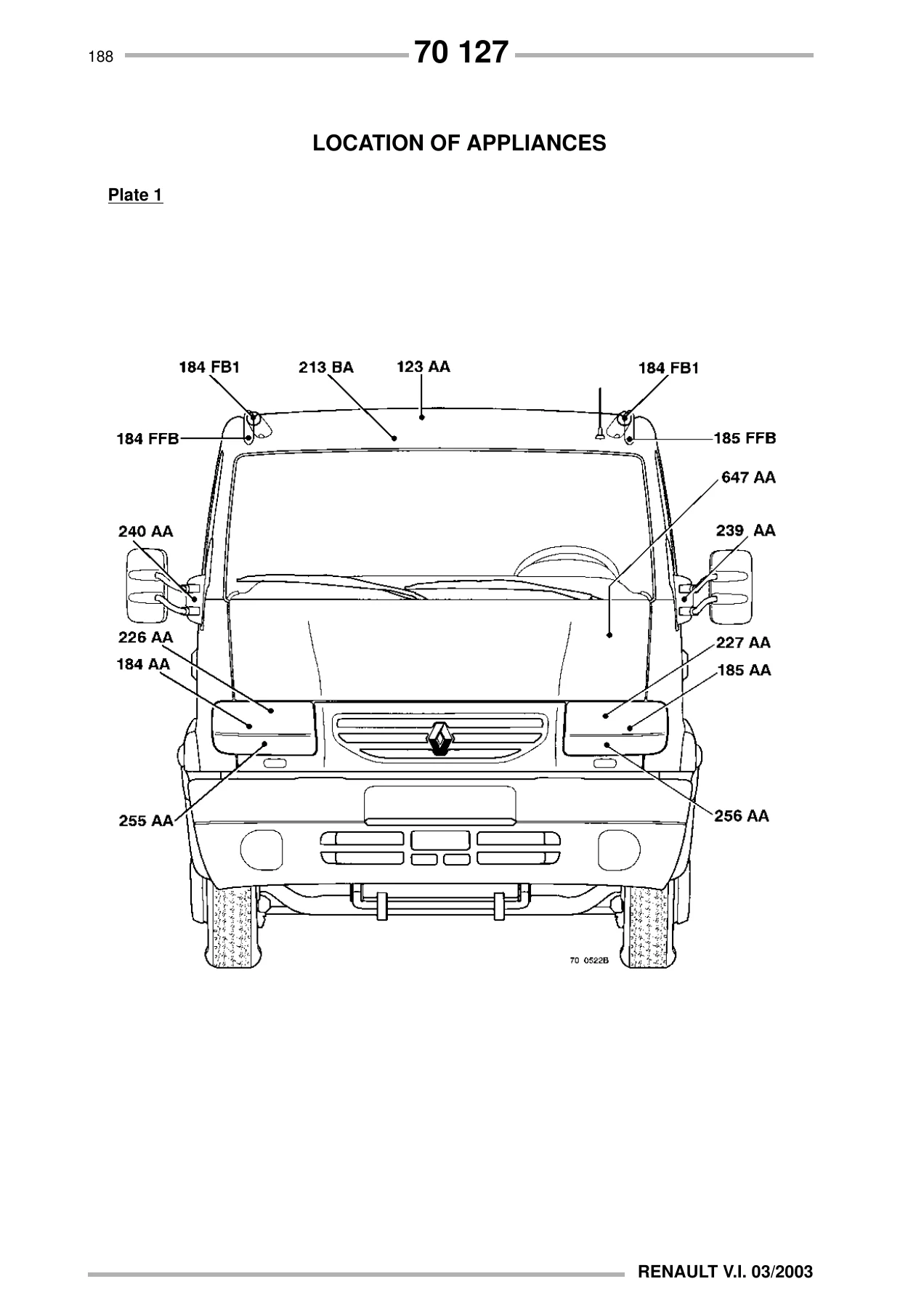
Chapter D situates each electrical appliance on the vehicle using cab, chassis and major unit illustrations. Starting from a unit’s item number, you look up the equivalence table at the beginning of the chapter to find the location plate, then locate the coded item on the drawing. The plates cover the cab front and rear views, the driver’s and passenger’s sides, the top-down chassis layout, engine bay components (alternator, starter, battery set, engine ECU, injectors, sensors, high-pressure pump), the fuel tank area (fuel level sender, fuel filter), the front end (headlamps, flashing lamps, horn, front parking lamps, ABS sensors), the rear end (rear signalling lamps, rear fog lamp, reversing lamp, brake pad wear switches), and the roof area (roof lamps, marker lamps, interior lighting). Earth points M2 through M16 are also located with reference to the plates on which they appear.
Fuses, Relays and Connection Units
Chapters E and F list every fuse and relay on the two connection units: BFR (Box/Fuses/Relays) situated under the steering wheel in the cab, and BIM (Engine Insert Box) situated on the front end of the chassis. The fuse tables give the fuse reference (FU1 through FU46), amp rating and assignment for each position on the BFR unit, and the power fuse table covers FU1 through FU12 on the BIM unit. The relay tables give the relay reference (C, D, E, F, G, H, J, K, M, P, Q, R and the numbered relays 260FCA, 260FCB, 260FCG, 258FAA, 273FWA, 804FBA), amp rating where applicable, assignment and the diagram plates on which the relay appears. Notes explain which BIM power fuses feed which BFR fuses in the cab, so you can trace a blown fuse back to its source without pulling the wrong box.
Instrument Panel, Power Supplies, Trailer Socket and Earths
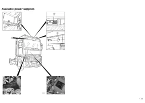
Chapter G presents the two instrument panels available for the Mascott DCI – with and without tachograph – and lists every warning lamp, tell-tale lamp and gauge with its item number (T01 to T35) and plate reference. Chapter H shows the possibilities for making electrical connections to the chassis and in the cab, including the 884 FB4 connector, the standby wires in the LH sidemember, the standby wires at the bulkhead grommet and the pre-arranged fuse locations on the BFR unit. Chapter I gives the terminal assignments for the 12N trailer socket and the R233 hook-up connector, with wire numbers, colours and fuse references. Chapter J lists all earth points on the vehicle (M2 through M16) and situates them in photographs, with a plate reference for each.
Who This Manual Is For
This Renault Mascott DCI electrical workshop manual is written for technicians, fleet maintenance workshops, auto-electricians and owners who need to diagnose and repair the electrical systems on Mascott DCI trucks rather than guess at wiring colours, fuse ratings or relay positions. The function-based diagram layout means you can work through a circuit in the order the current flows, which shortens fault-finding considerably compared to generic wiring diagrams. The appliance location plates mean you can find the physical component quickly once you know its item number from the diagram.
Why the Renault Mascott DCI Electrical Workshop Manual 70 127 Matters
Electrical faults on commercial vehicles are rarely solved by swapping parts. They are solved by knowing which wire carries which signal, which fuse protects which circuit, which relay switches which load, and where the earth point actually sits on the chassis. The Mascott DCI is no exception. The common rail fuel-injection system, the ABS, the engine immobilizer and the radio-frequency central locking all depend on clean power supplies and reliable earths, and a single corroded earth or blown fuse can produce symptoms that look like a failed ECU. This manual gives you the wire numbers, colours, sections, connector codes and plate references to isolate the fault instead of guessing.
IMAGES PREVIEW
Instant PDF Delivery – No Shipping, Any Device
The Renault Mascott DCI electrical workshop manual 70 127 is delivered as an instant PDF download. There is no shipping, no waiting for a courier and no risk of a damaged paper copy. Once your payment is complete the file is available immediately, and you can open it on a workshop laptop, a tablet on the bench or a phone beside the truck. Print the plates you need for the job and keep the rest on file. Whether you are chasing a charging fault on a Mascott DCI 110, tracing an ABS warning on a 140, or wiring a trailer socket on a 150, this is the document that tells you what the circuit should look like before you start.
Reviews
There are no reviews yet.