
Renault Trucks Electrical Wiring Diagrams Equipment & CAN J1939 2016-03 Export Manual PDF
Original price was: $44.95.$29.95Current price is: $29.95.
Complete Renault Trucks electrical wiring diagrams manual covering equipment circuits and CAN J1939 bus architecture, March 2016 export edition. Fuse and relay tables, connector pinouts, harness routing, available power supplies and every ECU diagram in one 354-page PDF.
Description
Renault Trucks Electrical Wiring Diagrams – Equipment and CAN J1939
This is the March 2016 export edition of the Renault Trucks electrical wiring diagram manual, published under document reference 225785. It is the diagram-side companion to the vehicle’s wiring harnesses: instead of showing only the schematic in isolation, it ties each circuit to its physical connector, fuse, relay and harness so a technician can trace a fault from a symptom to a specific pin. Coverage spans the cab, chassis, engine, gearbox, retarder, EBS braking, air suspension, AdBlue after-treatment and the vehicle’s CAN data buses.
Everything in this listing is drawn from the 354-page PDF itself. Nothing outside the document has been added, and no specification has been extended beyond what the pages print.
File Details
- Manual type: Electrical wiring diagrams – equipment circuits and CAN bus architecture
- Brand: Renault Trucks
- Document reference: 225785 / A
- Edition: 2016-03 Export
- Language: English
- Page count: 354
- File format: PDF
Chapters Covered
- Group 0 – Electronics
- Table of fuses on electrical distribution box
- Table of relays on distribution box
- Electrical distribution box – Face A connectors
- Electrical distribution box – Face B connectors
- Chassis / cab connection
- Available power supplies
- Supply feeds available inside the cab
- Dashboard wiring harness
- Steering column wiring harness
- Cab rear wiring harness
- Independent heating wiring harness
- Cab top ledge wiring harness
- Sun-roof wiring harness
- Roof wiring harness
- Anti-glare strip wiring harness
- Front end wiring harness
- Under-cab wiring harness
- Driver’s door wiring harness
- Passenger’s door wiring harness
- Chassis main wiring harness
- Cab / engine link-up wiring harness
- Gearbox wiring harness
- AdBlue wiring harness
- Cab / battery tray link-up wiring harness
- Front chassis wiring harness
- Wear sensors wiring harness
- Trailer sockets wiring harness
- Group 1 – Earths; Group 2 – Positive power supplies; Group 3 – Signalling; Group 4 – Comfort accessories; Group 5 – Safety accessories; Group 6 – Lighting; Group 7 – Onboard instruments; Group 8 – Auxiliary equipment and monitoring; Group 9 – Free
- List of equipment codes
- Summary of diagrams
- Individual diagram plates (Energy production, Electrical distribution, Vehicle electronic management, Engine management, Urea inflow, Gearbox, EBS, Suspension, Air production, Doors, Alarm, Tyres, Lighting, Radio, Heating, Air conditioning, CECU, Available power supply, Trailer sockets, Diagnostic socket)
- CAN bus architecture (J1587-1, J1939-1, J1939-2, J1939-ENG)
Group 0 – Electronics and Polarity Designations
This is the index of the whole document. The polarity number list assigns a designation to every numbered wire in the truck, and it is the reference you come back to whenever you meet an unfamiliar number on a diagram. You get J1587 and J1939 communication bus pairs, the radio remote control lines, the ZF transmission bus, retarder proportional and boost solenoid controls, the alarm siren encoded line, EBS trailer socket bus, vehicle speed sensor encrypted line, information display pull-down menu signals, gearbox input shaft speed, automatic gearbox casing oil level supply and identification line – each with its printed designation.
Fuse and Relay Tables
The fuse table is the practical starting point for a dead circuit. It lists each fuse code against the function it protects, the diagram folio it appears on, the fuse item number and the amperage: driver and passenger sun visor motors, principal information display, vehicle management ECU, cab tilting safety and power relays, tachograph, headlamp wash pump, immobiliser, alarm, doors central locking, air production management, bodybuilder pre-arrangement, air conditioning, cab temperature regulation, hydraulic retarder, lighting and signalling, wipers, cigar lighter, diagnostic socket, EBS braking management, PTO engagement electrovalves, horn and air horn, ABS/EBS trailer socket, window winders, add-on heaters, Datamax and positioning module, AdBlue supply pump, starter, water pump clutch, air preheating, exhaust brake and engine brake solenoid valves, piloted axle, tyre pressure monitoring, alternator earthing relay and more.
The relay table then gives the switching side of the same system: relay code, function, relay item number, amperage and diagram page, from after-ignition relays through to fog driving lights and accessories relays.
Electrical Distribution Box – Face A and Face B Connectors
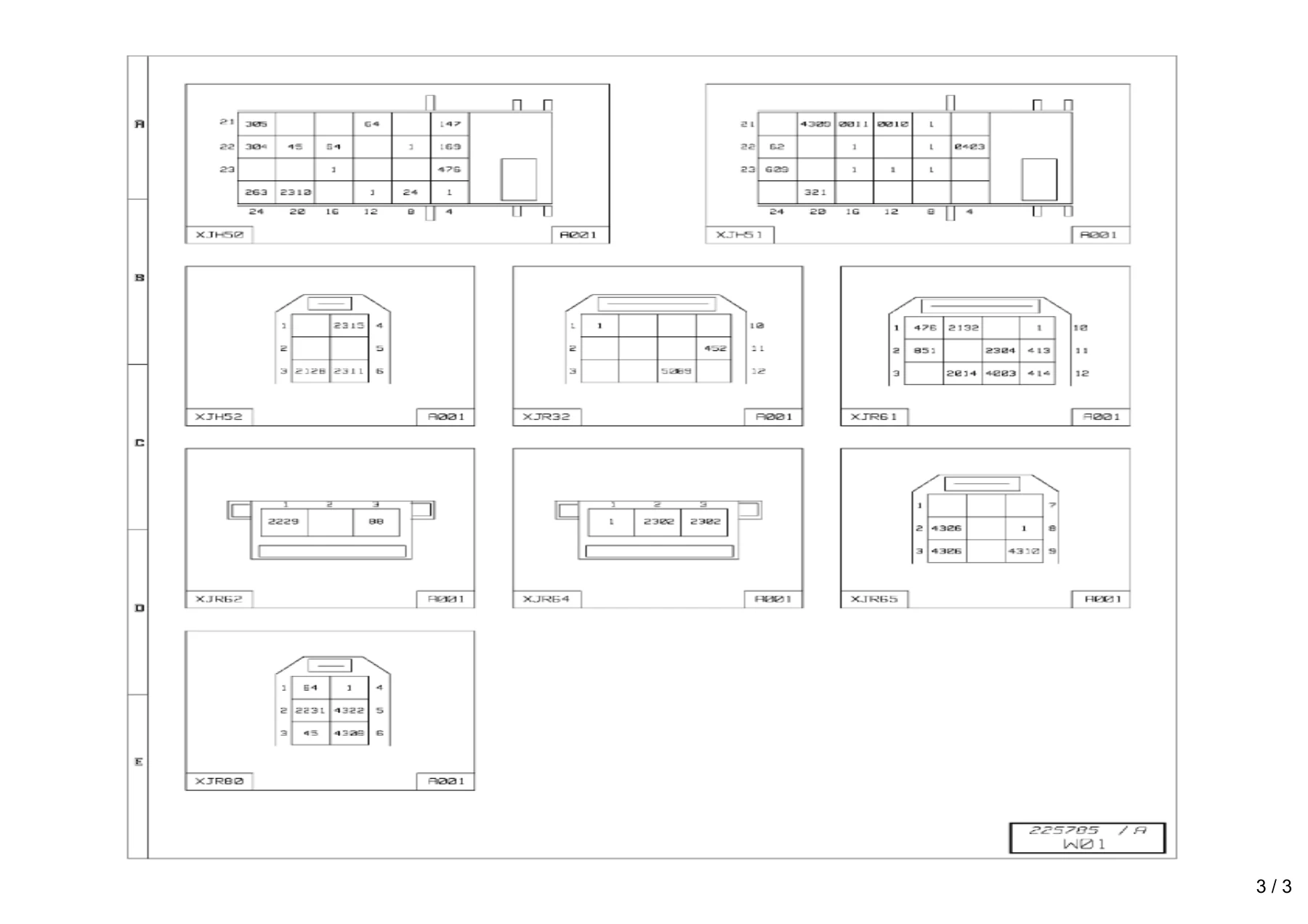
Both faces of the cab electrical distribution box are documented connector by connector. Face A lists connectors such as XJC40, XJH50, XJH51, XJH52, XJR32, XJR33, XJR61, XJR62, XJR64, XJR65, XJR73 and XJR80 with function name, colour and number of ways. Face B lists XJB15, the full XJC01_01 through XJC01_18 range, XJE21, XJF01, XJR11, XJR13 and XJR14. Each entry gives the wiring harness it belongs to, harness colour and pin count, and the following pages show the physical connector pin-out drawings with terminal numbering.
Chassis / Cab Connection
The chassis-cab interface is documented with the A34, XT01, XT12, XT13, XT15, XT16, XT21, XT22, XT33, XT41, XT53, XT63, XT65, XT70, XT71 and XT72 connector list – air conditioning, front end, rear line, piloted axles, trailer sockets, power unit, hydraulic retarder, RH front module, EBS/ESP, air suspension, independent heating and cab tilting equipment harnesses – followed by the pin-out drawings for each connector. The manual also confirms a reserved passage on the chassis-cab connection for the bodybuilder’s wiring harness.
Available Power Supplies and In-Cab Feeds
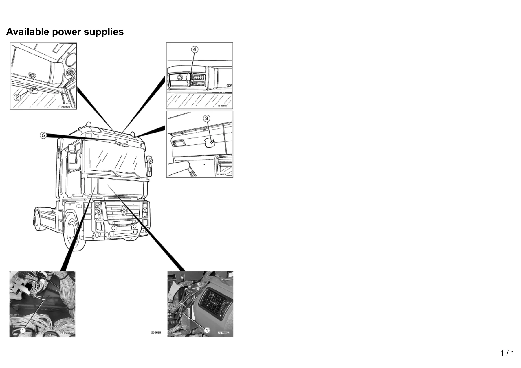
This section is written for anyone installing bodywork or auxiliary equipment. It shows the locations on the cab where a feed can legitimately be taken – location 1, 1′, 2, 3, 4 and 5 – with the function, polarity number, fuse item and amperage for each: vehicle earth, radio-telephone positive, night lighting, after master switch, onboard management screen and keyboard pre-arrangement, CB positive, lighting and side/parking lights. The in-cab connectors PB1, PB2, PB4 and PB5 are then broken down pin by pin, covering alternator information, gearbox neutral, reversing information, low speed, engine speed selection 1 and 2, PTO 1 and 2 controls, independent heating cut-off, road and working position warning pictograms, alarm stop, 6 km/h limitation, suspension level controls, engine start control, engine alert, engine starting information, PLC minimum outputs, CAN bus disabling, engine speed set-point validation, PTO solenoid piloting and parameter-definable frequency output.
Wiring Harness Sections
Each harness gets its own chapter with a connector table – code, function, connector reference, colour and number of ways – plus the pin-out drawings. The Dashboard wiring harness covers fourteen pages including the principal information display, air suspension ECU, bodybuilder pre-arrangement ECU, vehicle management ECU, EBS braking management ECU, tachograph, air conditioner control, lighting and signalling ECU, hydraulic retarder ECU, onboard management interface, gear selector, Datamax gateway, accelerator pedal sensor, steering lockover angle sensor, door open sensors, cab tilting motor relay, headlamp wash relay, the X200 available power supplies connector, and the full XJC01 series into the cab distribution box.
The Cab rear wiring harness documents the refrigerator, heated seat units, air/air add-on heater, cab temperature regulation ECU, cigar lighter, add-on heater temperature sensor, internal temperature sensor, parking brake indicator pressure sensor, stepwell lighting, reading spotlights, bunk overhead lights, air conditioning fan relay, headlamp ride corrector control, seatbelt sensor, air suspension remote control, sun-roof control, voltage converters, 12 V sockets and the rear link-up connectors.
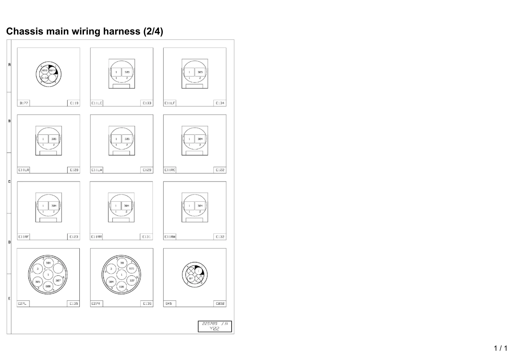
The Chassis main wiring harness covers the piloted axle ECU, tyre pressure monitoring ECU, fuel level sensor, lift-up air spring pressure sensor, drive axle suspension position and pressure sensors, piloted axle lockover angle sensor, chassis lateral acceleration sensor, middle axle suspension air pressure sensor, drive axle suspension pressure sensors, clearance lights, tail light units, rear inter-axle diff lock sensor, fifth wheel position sensors, braking assistance modulator units, diff lock and suspension control solenoid valves, front suspension electrovalve and axle piloting solenoid valve unit.
Other dedicated harness chapters include the front end, under-cab, driver’s and passenger’s door, cab top ledge, sun-roof, roof, anti-glare strip, cab/engine link-up, gearbox, AdBlue, cab/battery tray link-up, front chassis, wear sensors and trailer sockets. Gearbox coverage includes the automatic transmission ECU, PTO engagement electrovalves 1 and 2, tachograph speed sensor and PTO 1 engaged position sensor. AdBlue coverage includes the supply management pump module, nitrogen oxides concentration sensor, tank temperature and level sensors, heating resistors and metering solenoid valve.
Polarity Groups 1 to 9
The wire-number groups are printed in full so any numbered conductor can be identified from a diagram: Group 1 – Earths, with vehicle general earth and every ECU, sensor and injector earth; Group 2 – Positive power supplies, covering master-switch-switched and unswitched feeds, after-ignition feeds, radio antenna, GPS and GSM antenna coaxial lines, injector controls, automatic gearbox solenoid supplies and bodybuilder pre-arrangement feeds; Group 3 – Signalling, covering stop lights, direction indicators, hazard lights, parking lights, rear fog lights, horn and illuminated warning relay controls; Group 4 – Comfort accessories, covering window winders, mirrors, loudspeakers, air conditioning controls, sun-roof, curtains and central locking strikers; Group 5 – Safety accessories, covering retarder supplies, wipers, ABS solenoid valves, EBS module supplies and emergency stop switches; Group 6 – Lighting, covering main beam, dipped beam, fog driving lights, long range driving lights, reversing lights and searchlights; Group 7 – Onboard instruments, covering engine speed, fuel level, external and internal temperature, fifth wheel position and fleet management bits; Group 8 – Auxiliary equipment and monitoring, covering coolant level, diff locks, air suspension valves, PTO controls, engine speed control lines and AdBlue dosing; and Group 9 – Free, listing the available spare wires from cab to chassis and from dashboard to ledge.
Equipment Codes and Diagram Plates
The equipment code list is a full index of every lettered component in the vehicle electrical system – ECUs, sensors, switches, relays, motors, solenoid valves, resistors, diodes, connectors and units – with the function name and location for each. This means a code such as G012 (lighting and signalling management ECU) or V010 (PTO engagement electrovalve N°1) can be looked up directly and located on the correct diagram plate.
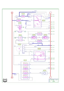
The diagram plates themselves are grouped by system: energy production with and without ADR, control ECU ADR, six electrical distribution plates, vehicle electronic management, principal information display, tachograph, onboard management (FMS, DATAMAX, OPTIFLEET), engine electronic management, urea inflow management, automatic gearbox, hydraulic retarder ECOSPLIT 2 and ECOSPLIT 4, EBS 6×2 and EBS 4×2 equipment, electronic air suspension variants, steered axle, air production management, doors and engine immobiliser, alarm, tyre pressure checking, three lighting and signalling management plates, side/marker/identification/parking lights, electric window winder and sun-roof, swivelling defrosting rearview mirrors, comfort accessories, radio, independent heating AT2000 ST and THERMO 90ST, air conditioning, bodybuilder pre-arrangement management, two available power supply plates, trailer sockets, diagnostic socket and the four CAN bus transfer zones.
CAN Bus Architecture
The final chapter maps the data bus topology across four transfer zones: J1587-1, J1939-1, J1939-2 and J1939-ENG. Each zone lists the ECUs sitting on that bus – vehicle management, engine management, bodybuilder pre-arrangement, air suspension, EBS braking, lighting and signalling, onboard management interface, gear selector, automatic transmission, hydraulic retarder, air production management, AdBlue supply module, engine immobiliser, alarm, Datamax gateway, tyre pressure monitoring, tachograph, radio set and diagnostic socket – and identifies the CAN bus grouping connector X203 and chassis-cab connection box A002.
Why This Manual Matters in the Workshop
Electrical faults on a modern truck are rarely a single broken wire. They are usually a corroded pin in a distribution box, a relay that has swapped function with its neighbour, a sensor sharing a bus with three other ECUs, or an earth that was never reconnected after a repair. Guessing at those faults costs hours. This manual removes the guesswork: you can identify the exact polarity number that appears on a diagram, follow it to its connector, confirm the pin, find the fuse that protects it, and see which ECU actually drives it.
The practical jobs this manual supports are broad. Fuse and relay diagnosis on the cab distribution box. Tracing a non-starting engine through the after-ignition and starting relay circuits. Diagnosing an EBS or ABS warning through the braking management ECU, modulator units and wheel speed sensors. Chasing an AdBlue fault through the supply pump module, nitrogen oxides sensor and heating resistors. Repairing air suspension levelling through the ECU, position sensors, pressure sensors and solenoid valve units. Sorting a retarder fault on either ECOSPLIT 2 or ECOSPLIT 4. Installing bodybuilder equipment on the officially available power supplies rather than tapping a harness. Diagnosing communication faults on any of the four CAN buses. And documenting everything for a customer or a fleet record.
Because the connector tables, pin-out drawings and polarity groups are all in one file, the manual works for both diagnosis and rework. If you are replacing a section of harness, adding a body, or fault-finding an intermittent, the reference you need is in the same document.
IMAGES PREVIEW
Instant PDF Delivery
This Renault Trucks electrical wiring diagrams manual is delivered as an instant PDF download. There is no shipping, no waiting for a disc, and no courier to chase. Once your order is complete the file is available immediately, so you can open it in the workshop, on a laptop, on a tablet or on a phone at the vehicle. Every page can be printed if you prefer a paper copy on the bench or a fold-out set on the cab floor. Keep it on file for as long as you own or service the vehicle – it will still be there the next time a circuit goes down.
Reviews
There are no reviews yet.