
Renault Trucks Electrical Wiring Diagrams Manual – Equipment & CAN J1939 – 2016-02 Export
Original price was: $59.95.$39.95Current price is: $39.95.
Complete electrical wiring diagrams for Renault Trucks equipment and CAN J1939 networks, dated 2016-02 Export. 223 pages of circuit diagrams, connector pinouts, fuse and relay locations, and ECU wiring for DXI7 and DXI11 engines, covering lighting, EBS braking, air suspension, retarders, automatic gearboxes, bodybuilder pre-arrangement, and onboard management systems.
Description
File Details
- Manual type: Electrical Wiring Diagrams
- Brand: Renault Trucks
- Coverage: Equipment and CAN J1939
- Edition/Date: 2016-02
- Document number: 70 7595 / A
- Language: English
- Page count: 223
- File format: PDF
Chapters Covered
- List of equipment codes
- Energy production (except ADR)
- Energy production ADR
- Control ECU ADR
- Electrical distribution (1/7 through 7/7)
- Air production management
- Lighting and signalling management
- Windscreen wiper(s) and headlamps wash
- Side, marker, identification and parking lights
- Rear lights
- Headlights and front lights
- Specific trade lights and horn
- Electric window raiser / Sun-roof
- Swivelling defrosting rearview mirrors
- Comfort lighting (1/2 and 2/2)
- Comfort accessories
- Radio, CB radio and telephone
- Air conditioning
- Independent (add-on) heating
- Diff lock
- EBS braking system
- Steered axle
- Automatic gearbox
- Gearbox ALLISON 3000V
- Electronic air suspension
- Electric retarder
- Hydraulic retarder
- Vehicle electronic management
- Bodybuilder pre-arrangement management
- Engine electronic management DXI11
- Engine electronic management DXI7
- Urea inflow management
- Alarm
- Door control / Immobiliser
- Tachograph
- Diagnostic socket
- Principal information display
- Trailer sockets
- Available power supplies
- Onboard management FMS + TMC
- Onboard management FMS + RAL
- CAN J1587 bus architecture
- CAN J1939 bus architecture
Equipment Codes and Component Identification
The manual opens with a comprehensive 14-page list of equipment codes, each with a function name and location reference. This is the master index for every component in the wiring diagrams: sensors, ECUs, relays, fuses, solenoids, switches, lights, motors, and connectors. Codes such as A001 (cab electrical distribution box), A004 (batteries), A006 (electrically controlled master switch), B103 (key switch unit), G001 (vehicle management ECU), and G002 (engine management ECU) are all listed with their locations. This section is essential for navigating the diagrams and cross-referencing components during diagnostics and repair.
Energy Production and Electrical Distribution
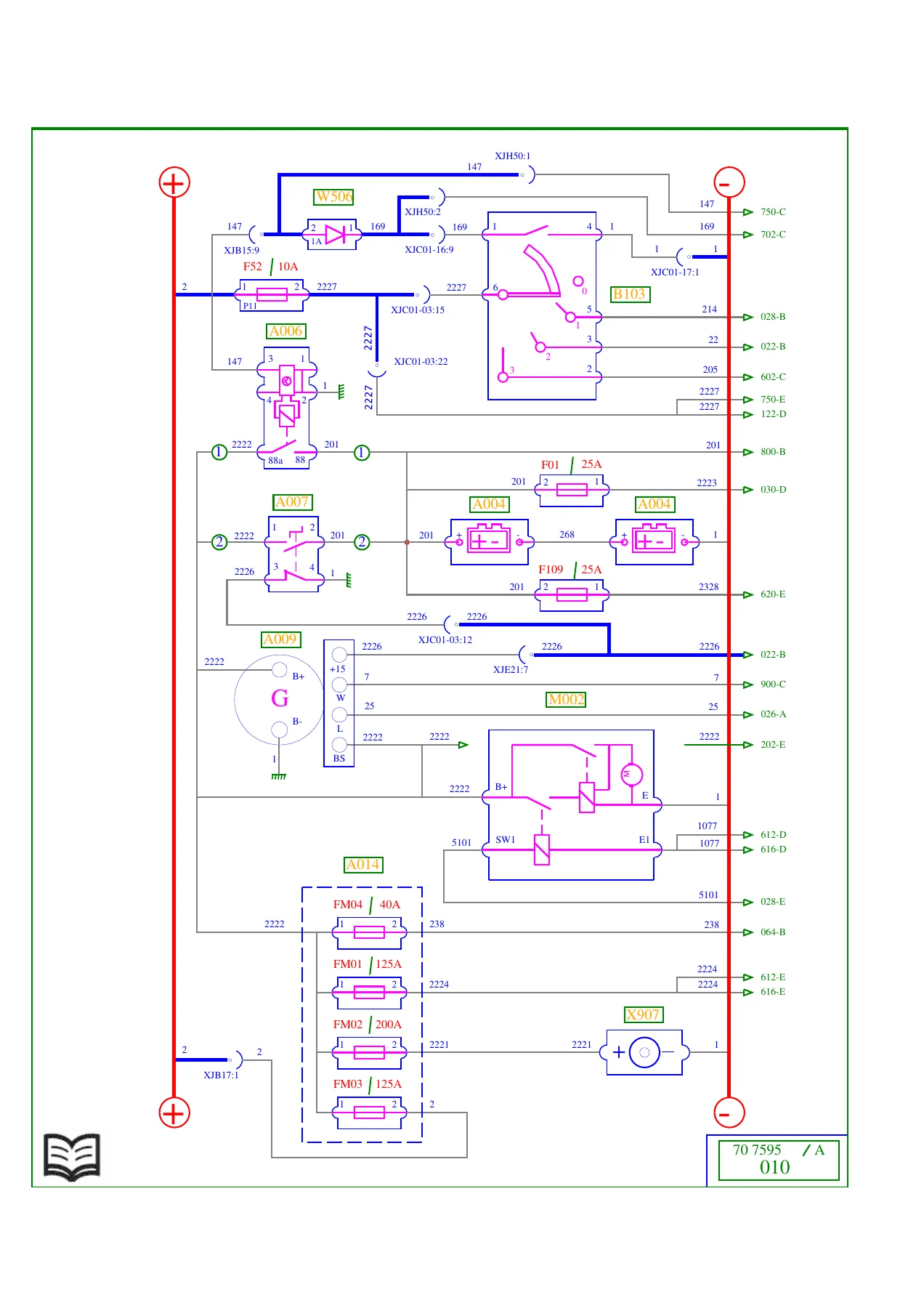
The energy production diagrams cover both standard and ADR configurations, showing battery, alternator, master switch, starter, and power fuse box (FM1 to FM4) circuits. The electrical distribution section is split into seven plates, each detailing fuses, relays, and power supply routing to all vehicle systems. The diagrams include the after-ignition power supply relays (S001, S002, S003), accessories power supply relays (S004, S005), starting relay (S020), and the alternator circuit earthing relay for ADR (S021). Fuse ratings such as F52 10A, F01 25A, FM01 125A, FM02 200A, and FM03 125A are clearly labelled, along with the X907 ground receptacle and X200 available power supplies connector.
Lighting, Signalling and Cab Systems
This group of diagrams covers the complete lighting and signalling management system, including side, marker, identification and parking lights, rear lights, headlights and front lights, specific trade lights and horn, and the lighting and signalling management ECU (G012). Also included are the windscreen wiper and headlamp wash circuits, electric window raiser and sun-roof controls, swivelling defrosting rearview mirrors, comfort lighting, and comfort accessories such as the cigar lighter, heated seats, and refrigerator. The diagrams show relay and fuse locations for stop lights, rear fog lights, main beam headlights, fog driving lights, reversing lights, and revolving beacons.
Braking, Suspension and Drivetrain
The EBS braking system is covered across seven plates, including ABS solenoid valves (V003, V004), braking assistance modulator units (G007, G008, G016), brake pedal sensor unit (C134), and trailer brake control EBS modulator (Z014). The electronic air suspension diagrams cover 4×2 tractors, 6×2 configurations, and other variants, with solenoid valve units, position sensors, and pressure sensors detailed. Drivetrain coverage includes the automatic gearbox, ALLISON 3000V gearbox, electric retarder, hydraulic retarder, and diff lock circuits.
Engine Management and Emissions
Dedicated sections cover engine electronic management for both DXI11 and DXI7 engines, including injector solenoid valves, boost air pressure and temperature sensors, engine oil level and temperature sensors, flywheel and camshaft speed sensors, and the engine management ECU (G002). The urea inflow management (AdBlue) section details the supply management pump module (G030), tank temperature and level sensors, heating resistors, and the metering solenoid valve.
Bodybuilder, Comfort and Onboard Management
The bodybuilder pre-arrangement management section covers PTO engagement controls, warning lights, and solenoid valve piloting. Comfort and convenience systems include air conditioning, independent add-on heating (AT2000ST, THERME90S, and ADR variants), radio, CB radio and telephone, alarm, door control/immobiliser, and tachograph. The onboard management sections cover FMS + TMC and FMS + RAL configurations, with the onboard management interface ECU (G018) and onboard management ECU (G102).
CAN Bus Architecture
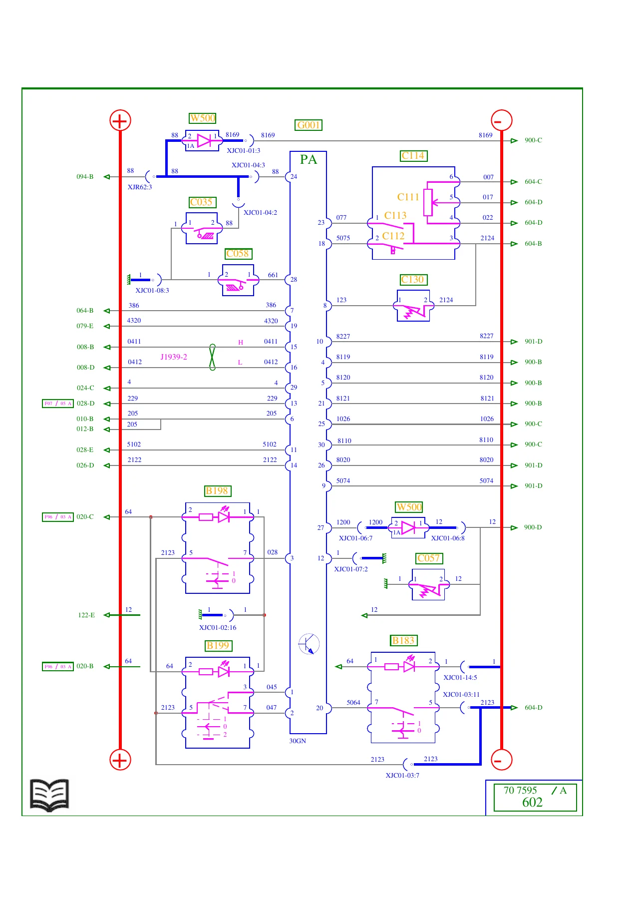
The manual includes detailed CAN bus architecture diagrams for J1587-1, J1939-1, J1939-2, and J1939-ENG transfer zones. These show how the vehicle management ECU, engine management ECU, EBS braking management ECU, air suspension ECU, automatic transmission ECU, retarder ECUs, and diagnostic sockets (X913, X914) are interconnected. The CAN bus grouping connector (X203) and bus wiring colours and pin assignments are clearly documented, making this section invaluable for troubleshooting communication faults.
Available Power Supplies and Trailer Sockets
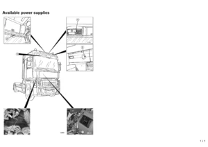
The final sections provide a complete breakdown of available power supplies, including insulated cut wires, vehicle earth, after master switch, after ignition, engine speed, PTO control, reversing information, parking brake information, gearbox neutral information, and chassis-mounted engine speed control. The trailer sockets section covers the 15-pin trailer socket (X900), ABS/EBS trailer socket (X906), and associated wiring for tractor and rigid vehicles.
Why This Renault Trucks Wiring Diagrams Manual Matters
Electrical faults on modern commercial vehicles are rarely simple. With multiplexed CAN networks, electronically controlled braking, air suspension, and engine management systems, guessing at wiring is not an option. This manual provides the exact circuit paths, connector pinouts, wire colours, fuse ratings, and component locations needed to diagnose and repair electrical faults correctly the first time. Whether you are tracing a fault in the lighting circuit, diagnosing a CAN communication error, repairing an EBS braking issue, or installing bodybuilder equipment, the diagrams in this manual give you the complete picture.
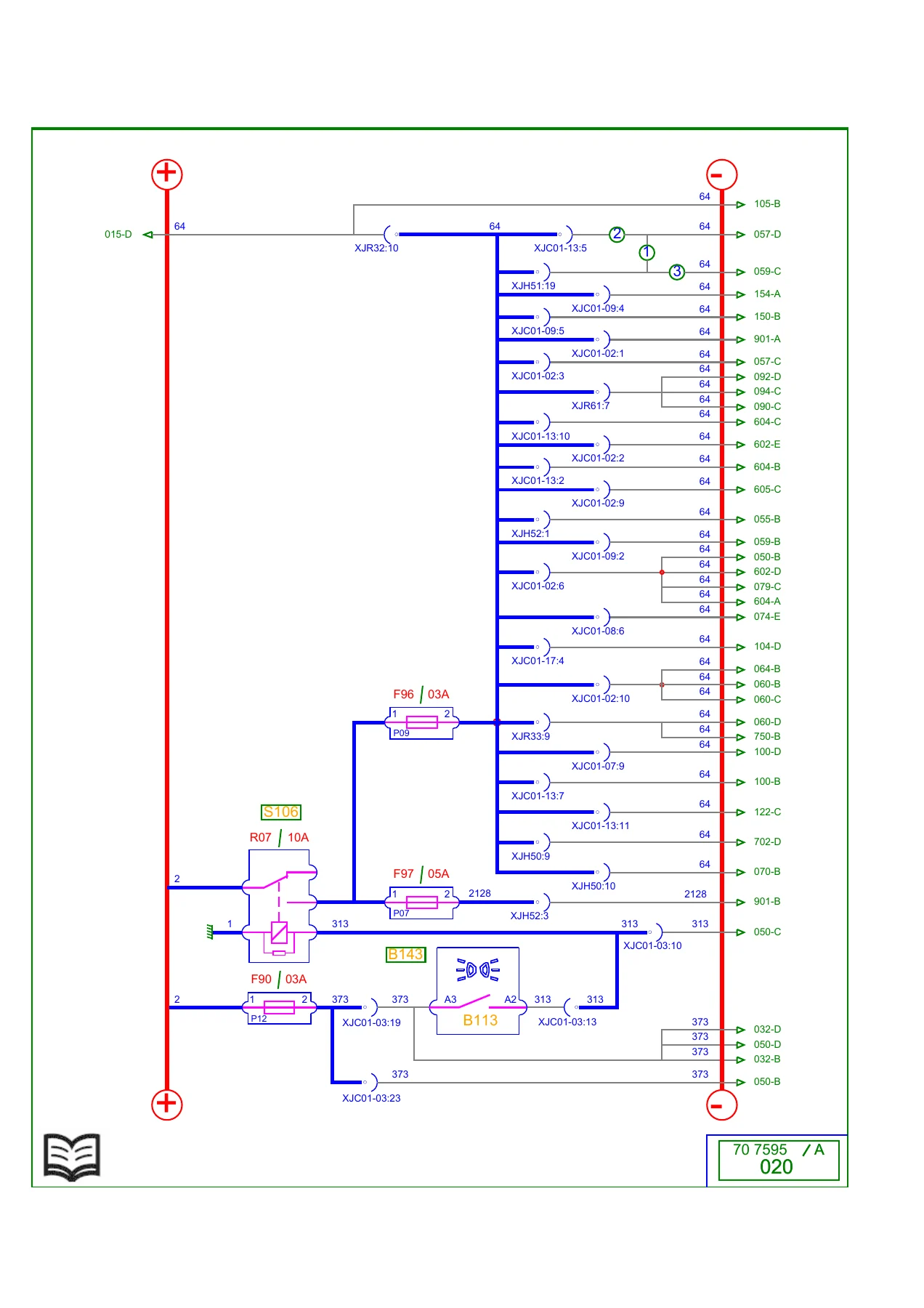
Each diagram plate is numbered (010, 012, 015, 020, 022, 024, 026, 028, 030, 032, 040, 050, 052, 053, 055, 057, 059, 060, 064, 069, 070, 074, 075, 079, 090, 092, 094, 100, 102, 103, 104, 105, 110, 120, 122, 150, 152, 154, 202, 204, 602, 604, 605, 610, 612, 614, 616, 620, 702, 750, 800, 805, 850, 851, 890, 900, 901, 902, 940, 941) and cross-referenced to the equipment code list, so you can move quickly from a fault code or a failed component to the relevant wiring diagram. The document number 70 7595 / A and date 2016-02 confirm this is a current and accurate reference for Renault Trucks vehicles built to Export specifications.
IMAGES PREVIEW
Instant PDF Delivery
This Renault Trucks Electrical Wiring Diagrams manual is delivered as an instant PDF download. No shipping, no waiting. Once payment is complete, you can download the file immediately and access it on any device — laptop, tablet, or smartphone. The diagrams are printable, so you can take the relevant pages to the workshop or keep a printed copy in the cab. Whether you are a fleet workshop, an independent technician, or a bodybuilder installing equipment, this manual gives you the wiring information you need, when you need it.
Reviews
There are no reviews yet.