
Renault Trucks D Narrow Wiring Diagrams 2019 – Complete Electrical Manual 337004/15
Original price was: $67.95.$44.95Current price is: $44.95.
Complete 626-page Renault Trucks D Narrow wiring diagrams manual (337004/15, February 2019). Full electrical schematics, fuse and relay tables, connector pinouts, CAN bus architecture, component locations, and body builder pre-equipment wiring for D Narrow vehicles.
Description
Renault Trucks D Narrow Wiring Diagrams Manual – 337004/15
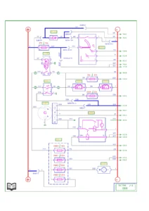
This comprehensive wiring diagrams manual covers the Renault Trucks D Narrow model range for the 2019 model year. Issued under document number 337004/15 and dated February 2019, this English-language manual provides the complete electrical architecture and wiring schematics for the D Narrow series. With 626 pages of detailed circuit diagrams, connector pinouts, component locations, and system schematics, this is the definitive electrical reference for technicians, fleet maintenance departments, and body builders working on Renault Trucks D Narrow vehicles.
File Details
- Manual Type: Wiring Diagrams Manual
- Brand: Renault Trucks
- Model: D Narrow
- Document Number: 337004/15
- Date: 2/2019 (February 2019)
- Language: English
- Page Count: 626
- File Format: PDF
Chapters Covered
- Communication Bus Architecture
- Wiring Diagrams
- Energy Production – Standard production, ADR
- Energy Distribution – Fuse and relay box internal circuits
- Vehicle Starting – Standard production, ADR
- Vehicle Management – Main ECU, information display, tachograph
- Engine Management – 5-litre and 8-litre engine control, injection, preheating, urea solution
- Gearbox Management – S3000, S2500, Automated Manual Transmission, Power take-off
- Driveline Management – Differential lock, transfer box
- Retarder Management – Electric retarder (before and after 04/12/2017)
- Braking Management – EBS equipment all options
- Suspension Management – Air suspension, rear air suspension
- Air Production Management
- Safety Management – Immobiliser, doors, alarm
- Lighting and Signalling – Headlights, rear lights, side lights, parking lights, night lighting, fog lights, reverse lamps, brake lights, horn, siren
- Driving Assist – Driving proximity radar
- Life on Board – Cab lighting, independent heating, air conditioning, radio, accessories
- Vehicle Maintenance – Cab tilting, hour meter, data link connectors
- Trailer Connections – Trailer sockets
- Body Builder System Management – Pre-equipment PB1-PB5, ECU, supplementary lighting
- CAN Bus Transfer Zones – J1587-1, J1939-1, J1939-2, J1939-ENG, J2284
- Location of Devices
- Electrical Distribution – Fuses, relays, diodes, connectors
- Available Power Supplies
- Trailer Sockets
- Wiring Harnesses – Routing for all systems
- Cab Inter-connectors
- Chassis Interconnectors
Communication Bus Architecture
This opening chapter maps the complete CAN bus network across the D Narrow vehicle. It covers the main CAN bus architecture, device coding tables, and the physical layout of the communication network. The key to devices provides the full code/title/location mapping for every ECU and communication node on the vehicle, including the engine ECU, gearbox ECU, braking system, suspension, lighting, and body builder modules.
Energy Production and Distribution
Covers the complete power generation and distribution system. Starting with standard production energy production diagrams, this section expands to ADR (dangerous goods) equipment variants. The energy distribution chapter details the fuse and relay box internal circuits across 8 sub-sections, showing every fuse rating, relay position, and internal connection. Specific coverage includes the 12V DC battery configurations, alternator circuit, power fuse box, and the electrical distribution box in the cab. Fuse tables provide the amperage rating, folio reference, and connected component for every fuse position.
Vehicle Starting
Includes both standard production and ADR starting system diagrams. The schematics cover the starting motor circuit, air intake preheating box, key-controlled contacts assembly, alternator shut-off relay, and associated diodes and resistors. Component location tables map every starting system device to its physical position on the vehicle.
Vehicle Management
This section covers the vehicle’s central management systems including the main ECU, main information display, and tachograph. The main ECU diagrams detail the vehicle and body builder pre-equipment management control unit, cruise control, speed limiter, and engine speed regulation controls. The tachograph chapter provides complete wiring for the tachograph unit, vehicle speed sensor, and DSRC antenna. The main information display section covers the instrument cluster wiring, fuel level sensor, brake lining wear sensors, and radio controls.
Engine Management
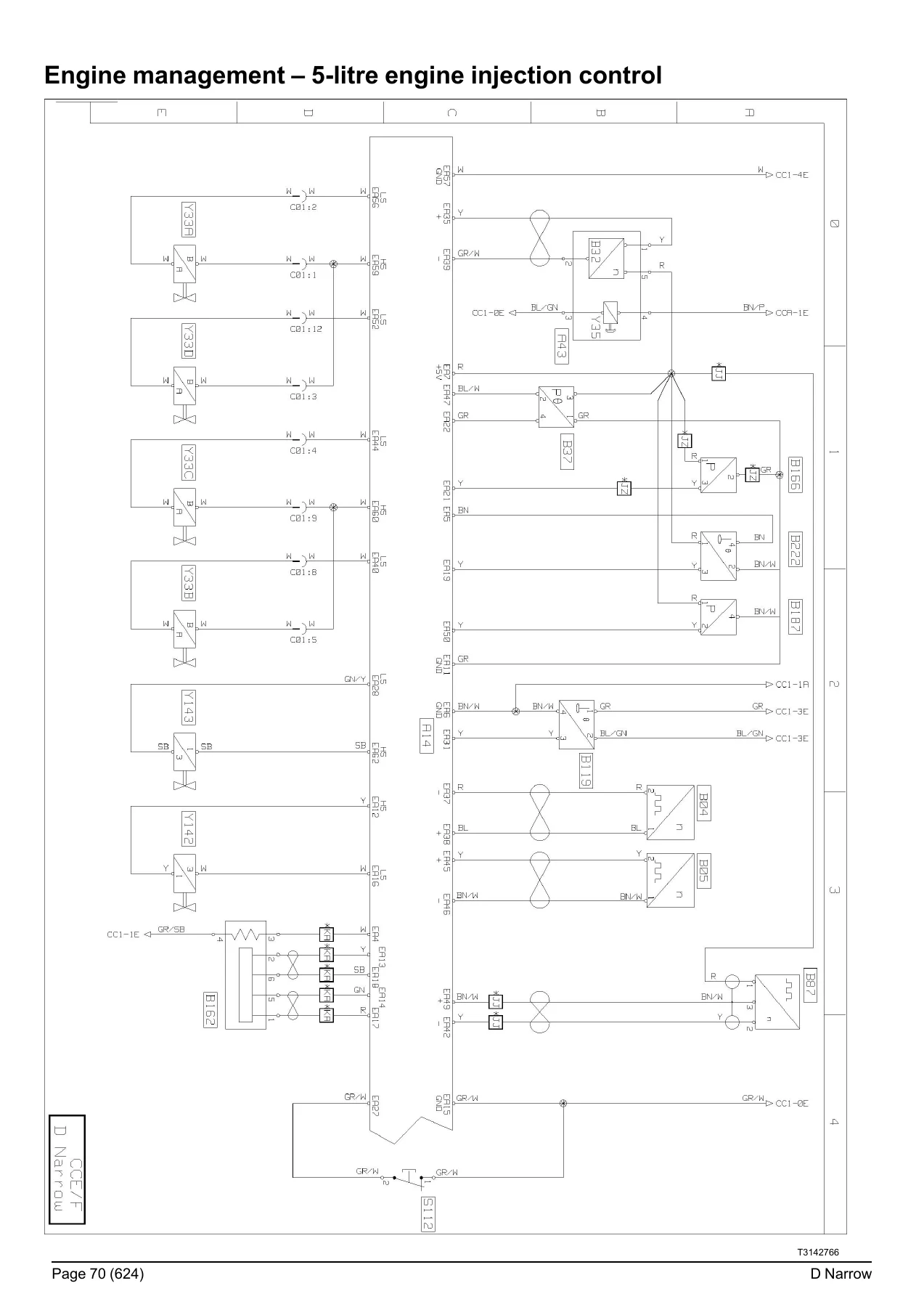
Split into 5-litre and 8-litre engine control, this is one of the most detailed sections of the manual. Each engine variant has dedicated control and injection chapters. The 5-litre engine section covers the engine ECU (EECU), exhaust gas recirculation, turbocharger control, rail high pressure regulation, and the engine preheating system. The 8-litre engine section adds engine brake solenoid valves and single H activation. The interface between engine and vehicle is fully documented, along with the complete urea solution addition system (SCR) covering the exhaust gas after-treatment control module (ACM), urea tank sensors, supply pump module, and NOx sensors.
Gearbox and Driveline Management
Covers all transmission options fitted to the D Narrow. The automatic gearbox chapters provide complete wiring for the ALLISON 3000 and 2500 gearboxes including the gear selector control unit, sensors/actuators unit, and output speed sensors. The Automated Manual Transmission (AMT) chapter covers the OPTITRONIC system with its control unit, gear selector, clutch position sensor, and electro-pump. Power take-off (PTO) wiring is documented for both standard and street-sweeper applications. The driveline section covers rear and front differential locks, transfer box control, and the low range selector system.
Braking, Suspension and Safety Systems
The EBS braking management chapter provides complete schematics for the electronic braking system including the brake pedal position sensor, wheel speed sensors, brake lining wear sensors, ABS solenoid valves, and the trailer brake control modulator. The suspension management section covers full air suspension for 4×2 vehicles including position sensors, pressure sensors, and solenoid valve assemblies, plus rear air suspension variants for vehicles with front mechanical suspension. Safety management covers the immobiliser system with transponder antenna, central door locking, rear door control, and the alarm system with presence detectors and siren.
Lighting, Signalling and Driving Assist
This major section covers all exterior and interior lighting circuits. Headlight diagrams include main beam, dipped beam, daytime running lights, fog lights, and headlamp height adjustment motors. Rear lights, side lights, beacon warning lamps, and side parking lights are fully documented. Control circuits for main beam, dipped beam, fog lights, reverse lamps, brake lights, horn, and the fire-fighting vehicle siren are included. The night lighting of controls chapter provides the complete dashboard illumination circuit. Driving assist covers the proximity radar system with camera unit and object detection sensors.
Life on Board
Covers all cab comfort and convenience systems. Cab compartment lighting is documented for standard production, 4-door cab, and various cab interior configurations. The independent heating system (AT2000 ST) wiring includes the heating management control unit, fan motor, ignition resistor, and fuel supply pump. Air conditioning covers the compressor electric clutch, evaporator temperature sensor, and cab compartment control module. Radio, speakers, microphone, and audio connectors are covered. Comfort accessories include heated seats, cigarette lighter, roof hatch, window lift motors, and electric blinds. Accessory sockets and voltage converters (24V/12V) are also documented.
Body Builder and Trailer Connections
Essential for body builders and fleet technicians, this section covers the body builder pre-equipment connectors PB1 through PB5 with complete pinout tables, available power supplies, and body builder pre-equipment ECU (A17) wiring. Trailer connections include the ABS/EBS 7-pin trailer socket and 15-pin trailer socket with full pinout descriptions. Supplementary lighting and fire-fighting vehicle pre-equipment are also covered.
CAN Bus Transfer Zones
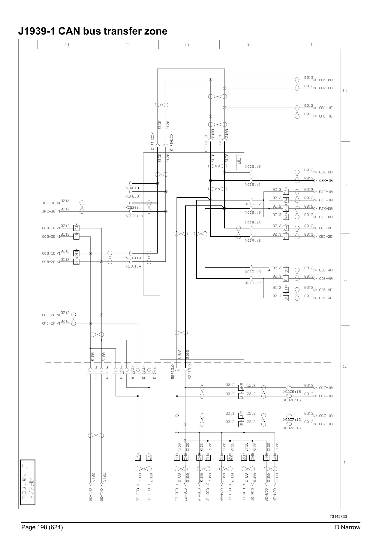
Five dedicated chapters document the CAN bus transfer zones: J1587-1, J1939-1, J1939-2, J1939-ENG, and J2284 main CAN bus. Each chapter provides the complete wiring for the data bus routing between the electrical distribution box and the various vehicle ECUs. These diagrams are essential for diagnosing communication faults and understanding the network topology.
Location of Devices and Wiring Harnesses
The location of devices chapter provides a comprehensive visual index of every electrical component’s physical position on the vehicle. The wiring harnesses section documents the routing of every harness in the vehicle, including electrical distribution, vehicle management, information display, tachograph, engine management (5-litre and 8-litre), urea injection, telematics, gearbox, retarder, EBS, air suspension, differential lock, transfer box, door control, alarm, air conditioning, audio, accessories, hour meter, driving assist, interior lighting, external lighting, windscreen wiper, trailer sockets, and earth harnesses. Each harness entry specifies the connector, colour, and pin count.
Electrical Distribution and Available Power Supplies
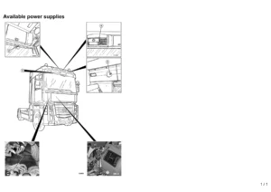
The electrical distribution section provides the complete fuse table for the EJB electrical distribution box (108 fuses), the relay table (29 relays), and the diode table. Fuses outside the distribution box are also documented for standard, street-sweeper, and forest fire tanker truck applications. The available power supplies chapter documents all customer-accessible power supply points inside the cab and on the chassis, with polarity, fuse marking, and amperage rating for each. This is indispensable information for safely installing additional electrical equipment.
Inter-connectors
Cab inter-connectors (ICC81, ICC82, ICH1, ICH2, ICH83, ICR81, and others) and chassis inter-connectors (XC301 through XC324) are documented with complete pinout tables showing designation, polarity number, and diagram page reference for every pin. These tables are essential for troubleshooting connector faults and tracing circuits across harness junctions.
Why This Wiring Diagrams Manual Is Essential
Electrical faults on modern commercial vehicles are among the most time-consuming and frustrating problems to diagnose without proper documentation. The Renault Trucks D Narrow is a sophisticated vehicle with multiple CAN bus networks, electronic control units for every major system, and hundreds of electrical connections. Without the correct wiring diagrams, technicians are forced to guess, probe, and waste hours chasing circuits through bundles of wires.
This manual eliminates that guesswork. With 626 pages of factory-derived schematics, component locations, connector pinouts, and fuse/relay tables, you get the exact information needed to:
- Trace circuits from the battery through the fuse box to the component and back to earth
- Identify the correct wire colour, gauge, and connector pin for every electrical connection
- Diagnose CAN bus communication faults by understanding the network topology
- Test sensors and actuators with accurate pinout and voltage specifications
- Install body builder equipment using the documented pre-equipment connectors and available power supplies
- Repair lighting, starting, charging, braking, suspension, and powertrain electrical systems
- Interpret fault codes by understanding which components and circuits are involved
Whether you are a fleet maintenance technician, independent workshop, body builder, or vehicle electrician, this manual gives you the same electrical documentation used by the professionals. Every diagram is clearly labeled with component codes, wire colours, connector references, and diagram page numbers, enabling fast navigation from a component location table to the exact schematic showing that circuit.
This is not a generic electrical theory book. It is the specific, model-accurate wiring documentation for the Renault Trucks D Narrow, covering the 5-litre and 8-litre engine variants, all transmission options, and the full range of body builder and fire-fighting vehicle configurations.
IMAGES PREVIEW
Instant PDF Delivery
Upon purchase, you receive immediate access to download the complete Renault Trucks D Narrow Wiring Diagrams manual in PDF format. There are no shipping charges, no waiting for a physical book to arrive, and no risk of a damaged or lost package. The PDF can be viewed on any computer, laptop, tablet, or smartphone, and individual pages can be printed as needed for use in the workshop. Keep it on your service laptop for instant reference during diagnostics, or print the specific diagram pages you need for a particular job.
With 626 pages of comprehensive electrical documentation covering every system on the D Narrow, this manual is a cost-effective investment that pays for itself the first time it saves you an hour of diagnostic time. Download your copy today and have the complete electrical reference for the Renault Trucks D Narrow at your fingertips.
Reviews
There are no reviews yet.