
Renault Midlum Euro 4 Wiring Diagrams Manual 70180/07 – PDF Download
Original price was: $59.95.$39.95Current price is: $39.95.
Complete Renault Midlum Euro 4 wiring diagrams manual (document 70180/07, February 2017) covering CAN bus architecture, electrical distribution, engine management, EBS braking, air suspension, body builder power supplies and every major electrical system. 302 pages of schematics, connector pinouts, fuse and relay tables.
Description
Renault Midlum Euro 4 Wiring Diagrams Manual – Document 70180/07
The Renault Midlum Euro 4 Wiring Diagrams Manual (document 70180/07, February 2017) is the complete electrical reference for Renault Midlum Euro 4 trucks. This manual covers the full electrical architecture of the vehicle range in exhaustive detail, from the CAN bus communication topology down to individual connector pin assignments, fuse ratings and relay locations. It is written in English and runs to 302 pages of schematics, diagrams, tables and component location references. Every electrical system on the Midlum Euro 4 is documented: engine management, braking, suspension, lighting, body builder interfaces and more.
Unlike a generic workshop manual, this wiring diagram manual gives you the actual circuit paths, wire colours, pin numbers and component codes needed to diagnose and repair electrical faults with confidence. Whether you are tracing an intermittent fault in the lighting circuit, rebuilding a damaged harness, or installing body builder equipment, the schematics and connector data in this manual tell you exactly what connects where, through which connector, and protected by which fuse or relay.
File Details
- Manual type: Wiring Diagrams / Electrical Schematics
- Brand: Renault Trucks
- Model: Midlum Euro 4
- Document number: 70180/07
- Edition / date: 2/2017 (February 2017)
- Language: English
- Page count: 302
- File format: PDF
Chapters Covered
- Communication Bus Architecture
- Wiring Diagrams
- Energy Production
- Electrical Distribution
- Vehicle Electronic Management
- Engine Electronic Management
- Managing the Urea Supply
- Differential Lock
- Gearboxes
- Electrical Retarder
- EBS Braking System
- Air Suspension
- Air Production Management
- Door/Immobiliser Management
- Alarm
- Lighting and Signalling Management
- Electric Windows, Sunroof
- Adjustable Heated Door Mirrors
- Comfort Accessories
- Radio
- Independent Heating
- Air Conditioning
- Body Builder Pre-equipment Management
- Available Power Supplies
- Trailer Connectors
- Data Link Connectors
- Equipment Locations
Communication Bus Architecture & CAN Bus
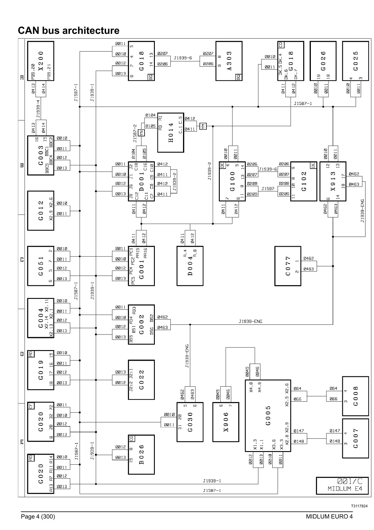
The manual opens with the complete CAN bus architecture for the Midlum Euro 4, covering the J1939-1, J1939-2, J1939-ENG and J1587-1 data buses. Full schematics show how the vehicle management control unit (G001), engine management ECU (G002), EBS control unit (G005), air suspension ECU (G004), body builder pre-equipment unit (G003) and other ECUs communicate across the network. Transfer zone diagrams for each bus (K20 through K23) map the connections between the dashboard, chassis and engine harnesses.
Electrical Distribution
Six dedicated electrical distribution sheets (A40 through A45) break down the vehicle’s power distribution from the battery and master switch through the cab distribution box, detailing every relay, fuse and power supply circuit. The fuse tables identify each fuse by code, amperage and the circuits it protects, from the main information display and tachograph to the night heater and trailer socket. Relay tables cover both in-box and out-of-box relays with their ratings and controlled functions.
Energy Production & ADR Equipment
Separate diagrams cover energy production with and without ADR equipment, including the alternator circuit, starter relay, battery master switch (electric or manual) and the ADR-specific alternator earthing relay. The ADR control ECU (G006) is documented for vehicles fitted with dangerous goods equipment, including cab and chassis emergency stop controls.
Vehicle Electronic Management
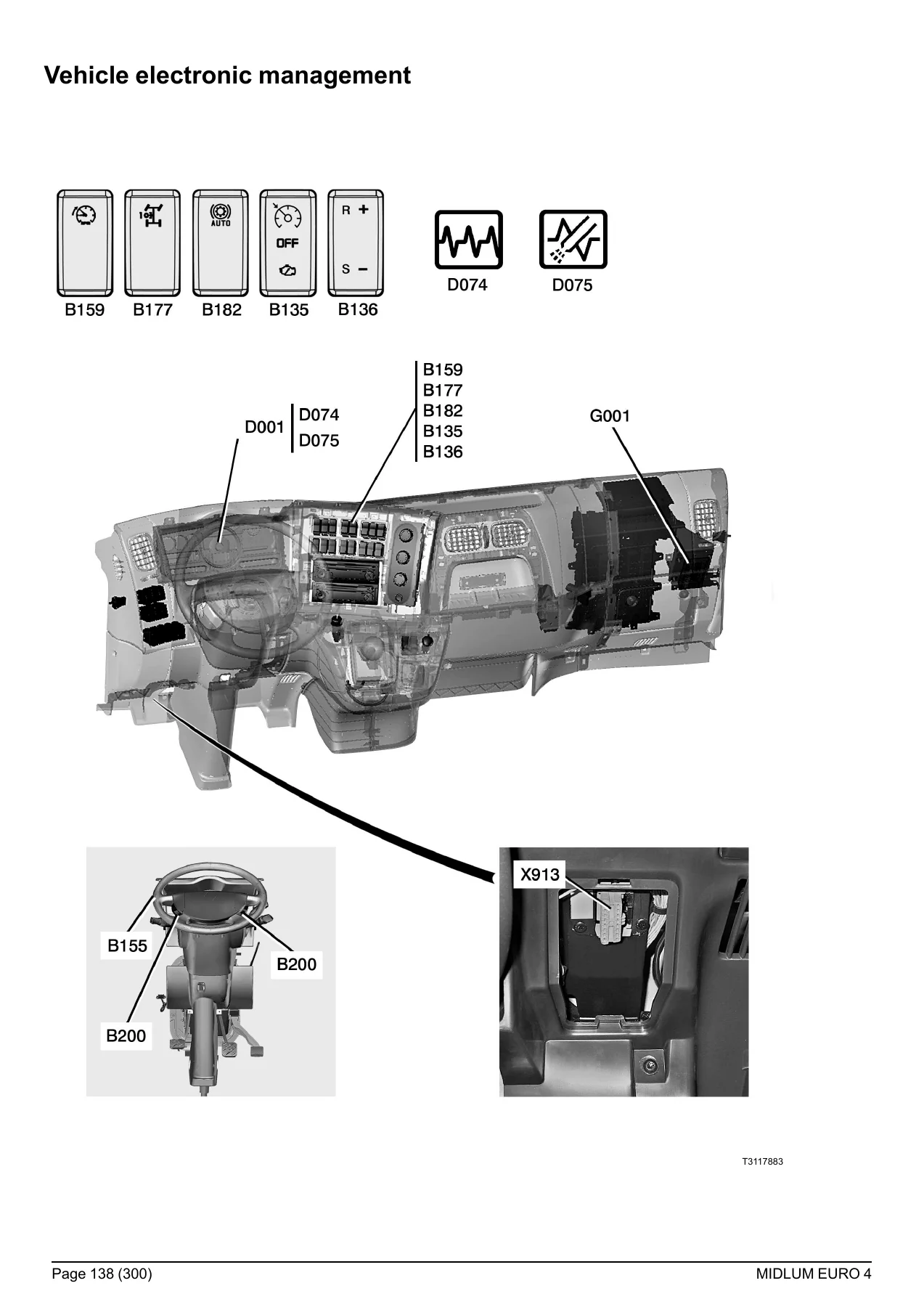
The vehicle electronic management section covers the VECU (G001) wiring in detail, including the throttle pedal sensor, cruise control, PTO engagement request, engine speed set-point controls, brake and clutch pedal sensors and the main information display. Complete connector pinouts for the dashboard harness are provided.
Engine Electronic Management (DXi 5 & DXi 7)
Dedicated diagrams for both the DXi 5 and DXi 7 engine management systems are included. These cover the engine ECU (G002), fuel high-pressure sensor, boost pressure and temperature sensors, oil level and pressure sensors, engine speed sensors, injector solenoid valves, engine brake solenoid valves and the air preheating system. Equipment location pages show the physical position of each sensor and actuator on the engine.
Urea Supply Management (AdBlue)
The urea supply section documents the complete SCR system: urea pump module (G030), level and temperature sensors, nitrogen oxide concentration sensor (C077), exhaust gas temperature sensor (C076), urea heating resistors (N015 to N019), metering solenoid valve (V056) and the engine coolant by-pass solenoid valve (V055). Both schematic and photographic equipment location pages are included.
Gearboxes & Retarder
Wiring diagrams for the 6AS800/6AS1000 automated manual gearbox (D01), the Allison 3000V (D02) and the Allison S2000 (D03) are provided, covering the gear selector, control unit, sensors, actuators and diagnostic sockets. The electrical retarder section (D30) documents the retarder control unit, relay box and retarder assembly.
EBS Braking System
The EBS braking system diagrams cover the EBS management control unit (G005), braking assistance modulators on the front and drive axles, wheel speed sensors, brake lining wear sensors, brake pedal sensor, trailer brake control EBS modulator and the ABS/EBS trailer socket. Both 4×2 and 4×4 configurations are documented.
Air Suspension
Three air suspension variants are covered: 4×2 rear electronic air suspension (1 sensor, under 18 t), 4×2 full electronic air suspension (under 18 t) and 4×2 full electronic air suspension (18 t and above). Each diagram set includes the suspension control unit (G004), position sensors, pressure sensors, solenoid valve assemblies and the remote control unit.
Lighting, Signalling & Comfort Systems
Three lighting and signalling management sheets (H01 to H03) document the lighting control unit (G012), headlamps, direction indicators, marker lights, fog lights, brake lights, reversing lights, work lights, horn, windscreen wipers and washers, and the rotating beacon circuit. Additional sections cover electric windows and sunroof, heated and swivelling door mirrors, radio and audio connectors, independent heating (AT 2000ST, including ADR variant) and air conditioning.
Body Builder & Available Power Supplies
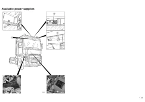
For body builders and upfitters, the manual provides the body builder pre-equipment management control unit (G003) diagrams, PTO 2 and PTO 3 engagement circuits and comprehensive available power supply connector tables. These tables list every available take-off point (J20, J21, PB1 to PB5, and others) with function descriptions, wire numbers, fuse ratings and polarity, including engine speed signals, PTO controls, reversing information, parking brake status and CAN bus access.
Trailer Connectors & Data Link Connectors
The 15-pin trailer socket (X900) and 7-pin ABS/EBS trailer socket (X906) pinouts are documented with fuse ratings for each circuit. Data link connectors (K01) cover the vehicle diagnostic socket (X913) and its connections to the J1587-1 and J1939 bus networks.
Equipment Locations
A dedicated equipment locations section provides photographic references showing the physical position of components on the vehicle, including dashboard controls, ECUs, sensors, valves and harness routing. This bridges the gap between the schematic diagram and the actual truck, making it faster to locate a connector or component during diagnosis or repair.
Fuses, Relays & Connectors
The manual includes a complete table of fuses on the electrical distribution box (F02 through F108), a table of fuses outside the distribution box (F01, F89, F98, F109, FM01 to FM04), a table of relays on the distribution box (S001 to S300) and a table of relays outside the box (S108, S401, S501, S502, S900, S904, S915, S916). The connectors section documents every dashboard harness connector with its code, colour and pin count.
Why This Wiring Diagrams Manual Matters
Electrical faults on modern commercial vehicles are rarely solved by swapping parts. They are solved by understanding the circuit: where power comes from, which connector it passes through, which ECU controls it and what conditions trigger it. This manual gives you that understanding for every system on the Renault Midlum Euro 4. The combination of full schematics, CAN bus architecture, connector pinouts, fuse and relay tables, and photographic component locations means you can trace a fault from symptom to source without guessing.
For fleet workshops, independent garages and owner-operators running Midlum Euro 4 trucks, this manual eliminates the downtime that comes from waiting on dealer information or chasing wiring blind. Body builders and upfitters will find the available power supply tables and body builder pre-equipment diagrams essential for safe, code-compliant installations.
IMAGES PREVIEW
Instant PDF Delivery
This Renault Midlum Euro 4 wiring diagrams manual is delivered as an instant PDF download after payment. No shipping, no waiting. The file works on any device, including laptop, tablet or smartphone, and every page can be printed for use in the workshop. Keep it on a tablet at the truck, print the specific schematic you need for a job, or archive it for future reference. The PDF format makes it easy to zoom and navigate across all 302 pages of electrical data.
Whether you are diagnosing a fault today, planning a body installation next week, or building a reference library for your workshop, this manual gives you the complete electrical documentation for the Renault Midlum Euro 4 in a single PDF.
Reviews
There are no reviews yet.