
Renault Trucks C & D Wide Wiring Diagrams Manual 337003/10 – 2016 Electrical Service Guide PDF
Original price was: $95.95.$59.95Current price is: $59.95.
Complete Renault Trucks C and D Wide wiring diagrams manual, document 337003/10, dated September 2016. 586 pages covering CAN bus architecture, full system wiring diagrams, connector pinouts, fuse and relay tables, harness routings and equipment locations for C and D Wide trucks.
Description
Renault Trucks C & D Wide Wiring Diagrams Manual – 337003/10
This is the complete Renault Trucks C and D Wide wiring diagrams manual, document number 337003/10, dated September 2016. It covers the full electrical and electronic architecture of the C and D Wide truck ranges, providing the detailed circuit diagrams, connector pinouts, fuse and relay tables, and harness routing information needed to diagnose, repair and maintain the vehicle’s electrical systems.
File Details
- Manual type: Wiring Diagrams / Electrical Service Manual
- Brand: Renault Trucks
- Model: C and D Wide
- Language: English
- Page count: 586 pages
- File format: PDF
- Document number: 337003/10
- Edition/Date: 9/2016 (September 2016)
Chapters Covered
- Communication Bus Architecture
- Wiring Diagrams
- Equipment Locations
- Layout of Controls
- Electrical Distribution
- Chassis – Cab/Bulkhead Grommet Connection
- Trailer Connections
- Available Power Supplies
- Wiring Harnesses
- Cab Inter-Connectors
- Chassis Inter-Connectors
Communication Bus Architecture
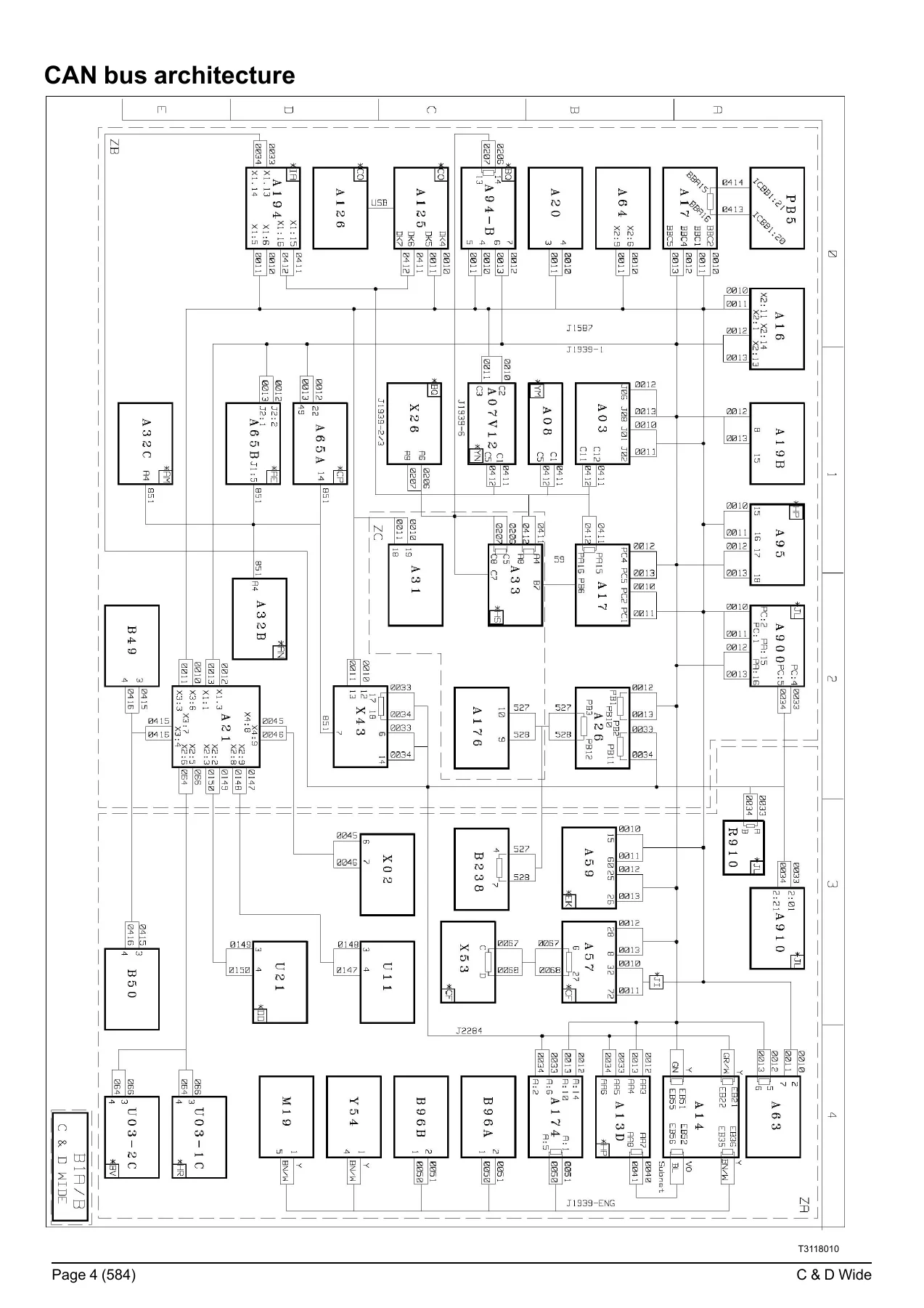
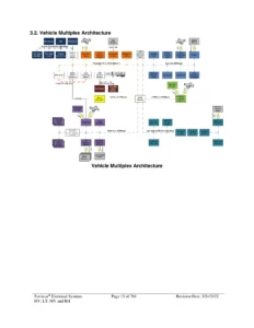
The opening section presents the complete CAN bus architecture for the C and D Wide, showing how the various electronic control units communicate across the J1587, J1939-1, J1939-2, J1939-ENG and J2284 networks. A key-to-devices table identifies every ECU by its code, function and location, covering components such as the engine electronic control unit (EECU), electronic braking system control unit (EBS), air suspension management control unit (ECS), automated manual transmission management control unit, and the on-board management system interface control unit. This section is essential for understanding network topology, diagnosing communication faults, and tracing signal paths between modules.
Wiring Diagrams
The main body of the manual contains the full set of system-by-system wiring diagrams, organised across 586 pages. Each diagram is accompanied by a key-to-devices table listing component codes, functions and diagram page references. Coverage includes:
- Vehicle management: Fleet management, telematics, tachograph, main ECU, main information display
- Engine management: 8-litre engine control (Euro VI Phase 1 OBDEP-A and Euro VI Phase 2 OBDEP-C), 11-litre engine control, gas engine control, injection control, engine preheating, urea solution addition (SCR), gas tank management
- Gearbox management: ALLISON generation 4 and 5 automatic gearboxes, OPTIDRIVER automated manual transmission, manual gearbox, power take-off
- Driveline and retarder management: Differential lock, electric retarder, hydraulic retarder, VOITH hydraulic retarder
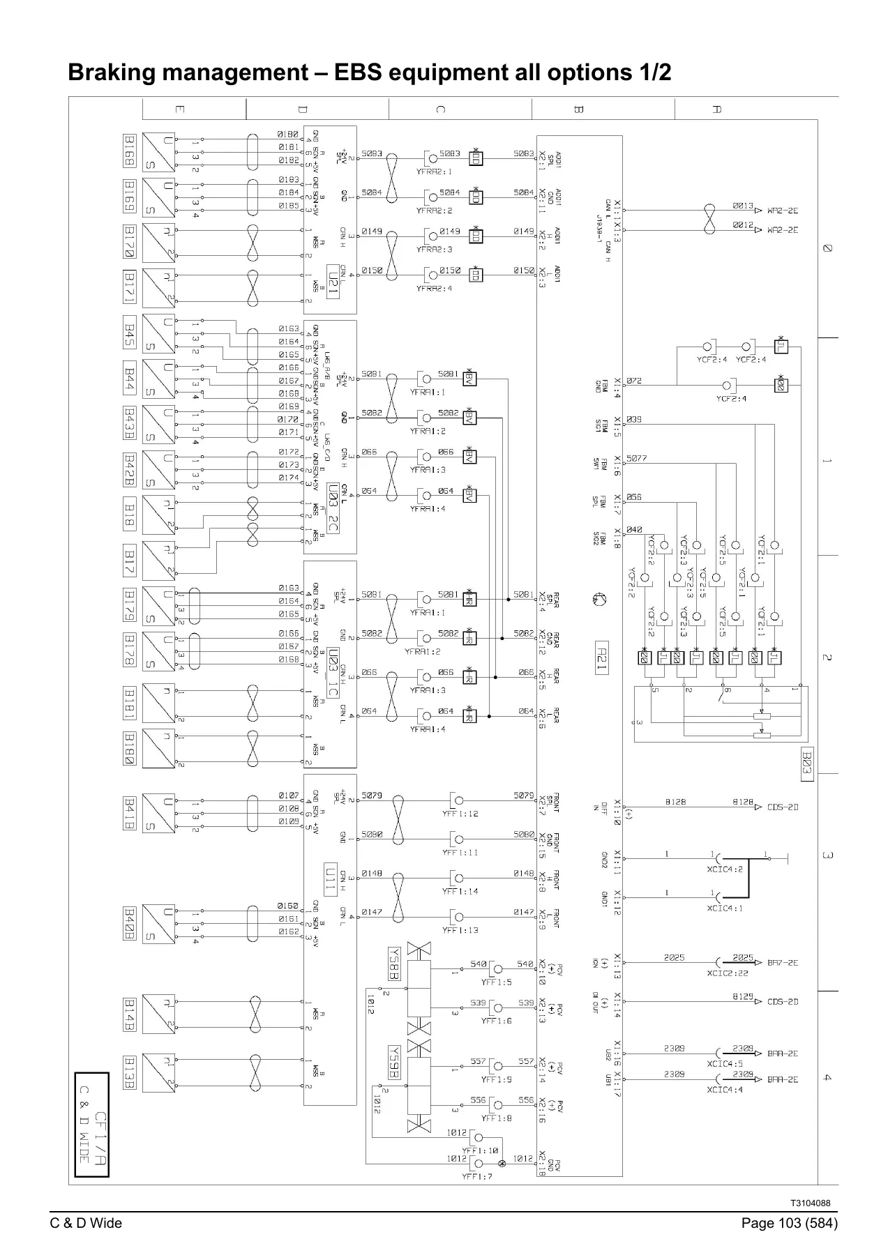
- Braking management: EBS equipment for 4×2, 6×2 and 6×4 configurations, all options
- Suspension management: 4×2 full air suspension, 6×2 air suspension, 6×4 air suspension, rear air suspension 4×2
- Controlled axle management: Electronically controlled rear axle steering (RASEC)
- Air production management: APM control unit circuits
- Safety management: Immobiliser and door control, alarm system
- Lighting and signalling: Headlights, rear lights, side lights, beacon warning lamps, side parking lights, parking lights control, night lighting of controls, main beam and dipped beam control, fog lights, reverse lamps, brake lights, horn, direction indicators
- Windscreen washing and wiping
- Rear viewing: Electric rear-view mirrors
- Driving assist: Driving radar, camera unit and object detection sensors
- Life on board: Cab compartment lighting, independent heating, air conditioning, comfort accessories, roof hatch and window lift, radio, accessory sockets
- Vehicle maintenance: Cab tilting and hour meter, data link connectors
- Body builder system management: Pre-equipment connectors PB1 through PB5, body builder pre-equipment ECU
- CAN bus transfer zones: J1587-1, J1939-1, J1939-2, J1939-ENG and J2284
Equipment Locations
This section provides a visual and tabular guide to the physical location of every major electrical and electronic component on the vehicle. It includes diagrams of the distribution box, main ECU, main information display, tachograph, engine electronic management (8-litre and 11-litre, Euro VI Phase 1 and Phase 2), gas engine management, gas tank management, urea solution top-up systems (32-litre, 50-litre, 68-litre and 64-litre tanks), FMS on-board management, OPTIFLEET, TGW2 telematics, energy production (manual master switch, electric master switch and ADR equipment), air production management, gearbox management (ALLISON generation 4 and 5, OPTIDRIVER, manual), retarders, EBS equipment (4×2, 6×2, 6×4), air suspension systems, controlled axle management, differential locks, door management, immobiliser, alarm, body builder pre-equipment, independent heating, air conditioning, radio, comfort accessories, driving assist, lighting and signalling management, interior and exterior lighting management, windscreen wash/wipe, trailer socket, and engine/chassis earths. Each location entry references the relevant diagram page for quick cross-referencing.
Layout of Controls
This section shows the physical layout of switches on the dashboard and on the overhead ledge, with a key-to-devices table that identifies each control by code, function and diagram page. Controls covered include the automatic transmission gear selector, work lamp lighting control, rear inter-wheel differential lock control, inter-axle differential lock, rear axle lift control, independent heating switch, headlamp level adjustment, roof hatch control, power take-off engagement controls, traction control cut-off (ASR), hill start aid, trailer brake holding control, vehicle emergency stop control, beacon warning lamps control, emergency call control, alarm panic button, hazard lights control, door locking control, body builder pre-arrangement controls, engine speed set-point control for difficult terrain, air suspension position access controls, axle load-shedding activation control, particulate filter regeneration activation control, work site mode activation control, tailgate pre-equipment control, AEBS system and lane departure warning. The overhead ledge layout covers microphone, reversing audible warning inhibition, alarm siren sound level reduction, door locking and ambience lighting controls.
Electrical Distribution
This is one of the most practically useful sections of the manual. It contains the complete fuse and relay tables for the EJB electrical distribution box, including fuse rating (in amps), folio reference, code, function and diagram page for every circuit. Separate tables are provided for the standard EJB box and the electrical distribution box used on gas vehicles. There are also tables of relays, diodes, and fuses located outside the distribution box, along with detailed connector pinout tables for Face A and Face B connectors – XCBB1, XCBB2, XCH1, XCH2, XCH3, XCR3, XCR4, XCR5, XCR7, XCR8, XCR11, XCR12, XCRI, XCRH, XCI1, XCI2, XCI3, XCIC1, XCIC2, XCIC3, XCIC4, XCIO1, XCIO2, XCIO3, XCIF1, XCIF2, XCIF3, XCIG1, XCIG2, XCIM1, XCIM2, XCIM3, XCIM4, XCIN1, XCIN2, XCIR1, XCIR2, XCIS1, XCIS2, XCIS3, XFB1, XFB2, XFD1, XFD2, XFD3, XFD4, XFF1, XFL1, XFL2, XFRC1, XFTP1 and XFTP2. Each pin entry gives the designation, polarity number and diagram page reference.
Chassis – Cab/Bulkhead Grommet Connection
This section documents the connectors that pass through the chassis-to-cab bulkhead grommet, including YCF1, YCF2, YFB1, YFB2, YFD1, YFD2, YFF1, YFF2, YFL1, YFS3, YFS4, YFS5, YFS6, YFR1, YFRA1, YFRA2, YFSA1, YFT1, YFTP1 and their pin assignments. These connectors are critical when tracing faults that cross between the cab and chassis harnesses.
Trailer Connections
Detailed pinout tables for the ABS/EBS 7-pin trailer socket (X02, X02_T) and the 15-pin trailer socket (X03, X03_T), including designations, polarity numbers and diagram page references for each pin.
Available Power Supplies
This section lists the available power supplies inside the cab, on the chassis, and at the body builder pre-equipment locations (PB1, PB2, PB3, PB4 and PB5). Each entry gives the function, polarity number, connector marking and fuse rating where applicable. Important safety notes are included regarding the prohibition of creating electrical take-off points on wiring harnesses and the mandatory use of type-approved connectors.
Wiring Harnesses
The final major section provides harness routing information for every major system, including electrical distribution (mechanical and electric master switch), vehicle management, information display, tachograph, 8-litre engine (Euro VI Phase 1 and Phase 2), 11-litre engine, urea injection, urea top-up (32/50-litre and 68/64-litre tanks), OPTIFLEET, TGW2, ALLISON generation 4 and 5 automatic gearboxes, OPTIDRIVER, manual gearbox with hydraulic retarder, electric retarder, EBS equipment (4×2, 6×2, 6×4), air suspension (4×2, 6×2, 6×4), controlled axle, differential locks (4×2/6×2 and 6×4), immobiliser and door control, alarm, air conditioning, audio system, accessories, hour meter, driving assist, cab interior lighting, external lighting on chassis, windscreen wiper/washer, trailer sockets, and earth wiring. Each harness entry lists the connectors, colour codes and pin counts.
Cab and Chassis Inter-Connectors
Complete pinout tables for cab inter-connectors (ICH1, ICH2, ICR1, XACD61, XACD62, XACR15, XADH01, XADH02, XAHH1, XAHH2, XAHR1, XAHR3, XAHR4) and chassis inter-connectors (XC301 through XC324), giving designation, polarity number and diagram page for every pin.
Why This Wiring Diagrams Manual Matters
Electrical faults on modern commercial trucks are among the most time-consuming and frustrating problems to diagnose without the right documentation. The Renault Trucks C and D Wide wiring diagrams manual gives you the complete electrical architecture of the vehicle – every circuit, every connector, every fuse, every relay and every earth point – in a single, coherent reference. Whether you are tracing an intermittent fault in the CAN bus network, replacing a sensor, repairing a damaged harness, adding body builder equipment, or performing a full electrical system diagnosis, this manual provides the accurate, vehicle-specific information you need to get the job done correctly the first time.
Using generic wiring diagrams or guesswork on a complex commercial vehicle electrical system leads to misdiagnosis, unnecessary parts replacement, and potentially costly damage to sensitive electronic control units. This manual eliminates that risk by showing you exactly how the system is configured for the C and D Wide, with connector pinouts that match the actual vehicle, fuse ratings that correspond to the real distribution box, and harness routings that reflect the physical layout of the truck.
IMAGES PREVIEW
Instant PDF Delivery
This Renault Trucks C & D Wide wiring diagrams manual is delivered as an instant PDF download – no shipping, no waiting. The file can be viewed on any device, including laptops, tablets and smartphones, and individual pages or complete sections can be printed for use in the workshop. Whether you are a fleet maintenance technician, an independent truck mechanic, a body builder integrating equipment, or a vehicle owner who prefers to understand the electrical system before authorising repairs, this manual gives you the same wiring diagram information used by professional service operations.
Reviews
There are no reviews yet.