

Schramm Drilling Rig Compressor Operation, Maintenance and Repair Training Manual – Spanish Edition
Original price was: $34.95.$22.95Current price is: $22.95.
119-page Spanish-language training manual for Schramm drilling equipment rotary screw compressors – operation theory, inlet and minimum pressure controls, air/oil separator service, lubricant specifications, clutch and coupling installation, and complete troubleshooting charts for T555 Rotadrill, T685WS and Sullair / GHH air ends.
Description
This Schramm drilling rig compressor operation, maintenance and repair training manual is a 119-page Spanish-language training document built around the rotary screw air compressors used on Schramm drilling equipment. It explains how a screw compressor actually makes air, how the air and oil circuits are laid out, how the inlet, minimum pressure and blowdown valves are sequenced, and how the compressor is serviced, adjusted and repaired in the field. Selected specification and notice pages appear in English, including the Schramm oil specification bulletin.
File Details
- Manual type: Operation, maintenance and repair training manual
- Brand / manufacturer: Schramm, Inc. (West Chester, PA, USA)
- Equipment covered: Drilling equipment rotary screw compressors
- Language: Spanish (selected specification and notice pages in English)
- Page count: 119 pages
- File format: PDF
- Document reference visible in the manual: Schramm Oil Specifications – 2011
Chapters and Subjects Covered
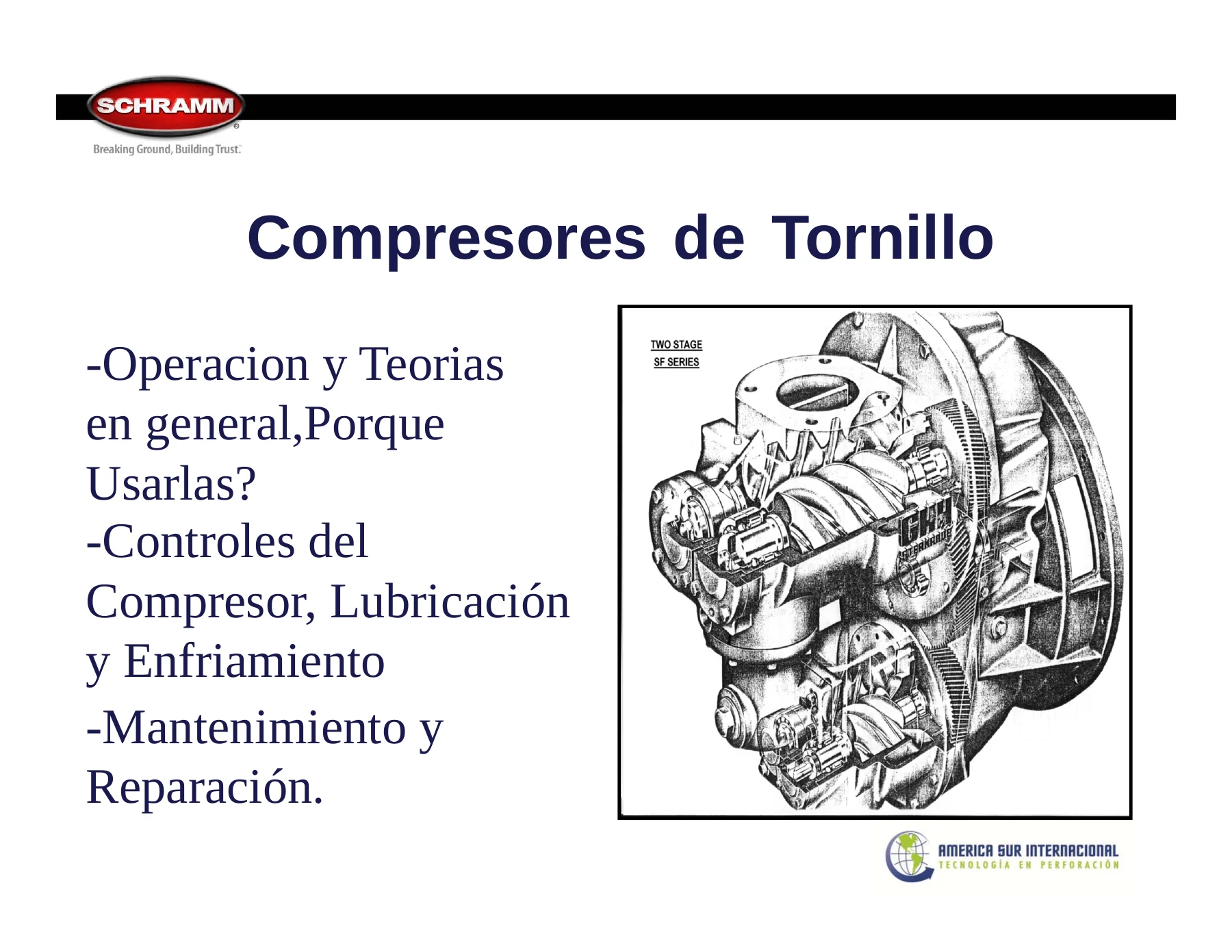
- Screw compressors – general operation and theory, and why they are used
- Compressor controls, lubrication and cooling
- Maintenance and repair
- Two-stage SF series compressor construction
- Why it is called a screw compressor – male and female rotor design
- Air flow through the male and female rotors
- Rotor clearance and sealing strip
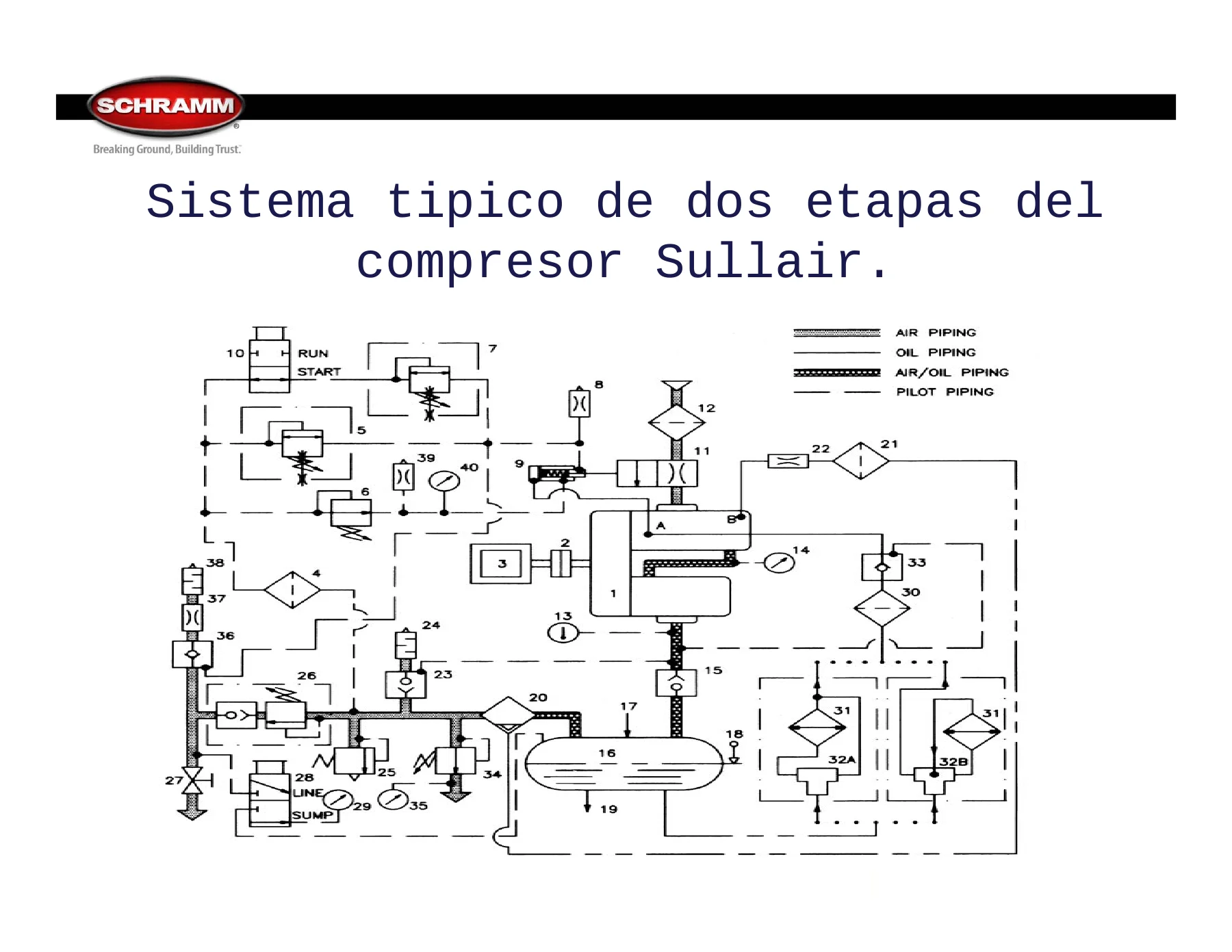
- Compressor system layout: air filter, inlet control valve, compressor unit (air end), discharge check valve, receiver (sump), air/oil separator, combination minimum pressure and check valve, air outlet, oil filter, thermal valve, compressor oil heat exchanger, oil stop valve
- Couplings – direct coupling and mechanical disconnect through the clutch
- Ringfeder coupling and drive adapter
- Sullair clutch assembly and clutch linkage adjustment
- Variable inlet control valve, mechanical air delivery control, automatic volume control
- Load and unload positions of the butterfly valve
- 500 PSIG compressor control circuit and pilot valve arrangement
- HP and LP regulators, regulator manifold
- Blowdown valve operation, 3:1 and 8:1 ratios, open and closed piloting
- Auxiliary air regulator and lubricator for air tools
- Minimum pressure valve settings for Schramm, GHH and Sullair
- Compressor oil stop valve and thermal valve
- Air/oil separator and separator element replacement procedure
- Compressor tank, scavenger line and scavenger filter
- Moisture control, water in oil and its effect on bearing life
- Recommended compressor lubricants and oil specification tables
- Installation of bell housing, drive yoke, clutch and inspection cover
- Troubleshooting: compressor will not discharge, excessive oil consumption, engine stall from high compressor temperature, low hole pressure, oil carryover through the compressor inlet
Working through the manual from front to back, a technician moves from the reason a rotary screw compressor replaced older designs – compact size relative to output, few moving parts, oil-flooded cooling and lubrication, and usable volume above 500 psi – into the hardware itself. The two-stage SF series air end is broken down visually, with the male and female rotors shown in section along with the rotor clearance and the sealing strip that separates the low and high pressure sides. From there the document follows the air: through the filter and inlet control valve, into the air end, out past the discharge check valve into the receiver, up through the air/oil separator and the combination minimum pressure and check valve, and finally out of the machine.
Controls, valves and regulation
A substantial share of the manual deals with control. The variable inlet control valve, the mechanical air delivery control and the automatic volume control are each shown installed and explained in terms of what moves and when. The butterfly valve is documented in both positions – open with the control cylinder extended in the loaded condition, closed with the cylinder retracted in the unloaded condition – including the 5/8 perforation in the disc. The 500 PSIG control circuit is laid out with the 225, 350 and 500 PSI pilot valves, the load/unload selector, the inlet control cylinder and the running blowdown valve. The regulator manifold is broken down by part number, and the HP and LP regulators are shown disassembled so the high pressure adjustment screw and the low pressure regulator can be told apart.
Separator, lubrication and cooling
The air/oil separator section is written as a job procedure rather than a description: removing the tank cover plate, loosening the grounding set screw and jam nut, removing the seal plate, discarding and replacing the separator element, seating the new element between the tabs in the bottom seal plate, re-tightening the seal plate nuts evenly without over-tightening, locking the grounding screw against the metal end of the separator, and refitting the cover with a cover bolt torque of 280-300 lb-ft (406 Nm). Lubrication coverage includes the oil stop valve, the thermal valve, the oil cooler, the minimum pressure valve settings, and the factory lubricant recommendations with comparative viscosity, viscosity index, copper strip corrosion, rust and flash point data. A dedicated page explains how water contamination shortens bearing life, with the relationship between remaining bearing life and parts per million of water in the oil.
Installation and assembly work
Several sections document the mechanical assembly of the compressor package: fitting the bell housing, removing the drain tube before installation and refitting it afterwards, sliding the yoke over the two Woodruff keys, connecting the grease fitting and hose to the bell housing, seating the clutch on its taper before fitting the lock washer and nut, and torque figures for the drive train including 200 ft-lbs at the clutch nut and 250-270 lb-ft on the clutch operating shaft. Clutch throwout bearing greasing is called out at monthly or 100-150 hour intervals with a warning not to over-grease, and the manual states plainly that the clutch must not be engaged with the engine running.
Drilling air performance
The manual ties the compressor back to the hole, noting that the recommended air sweep velocity in the hole is between 4,000 and 7,000 fpm and that annular velocity is dictated by compressor CFM together with bit and drill pipe diameters. Compressor nameplate data is reproduced for the machines shown, including the 1050/350 compressor rated at 1050 SCFM at 350 PSIG and 1800 RPM, the Sullair DC 1070/500 unit with its rated 500 PSIG air pressure, and the 1350/500 compressor.
Troubleshooting charts
Fault sections are organised by symptom and cause, which is what makes this manual genuinely usable at the rig. “Compressor will not discharge” lists a sticking inlet throttle valve, a stuck or leaking inlet control cylinder, regulators needing adjustment, restricted or leaking control lines, open filter drain lines and frozen air lines. Excessive oil consumption points to overfilled sump level, plugged or loose hoses, dirty scavenger orifices, a ruptured separator element, incorrect recycle tube level, foaming oil and low minimum pressure setting. High compressor temperature shutdown covers dirty cooler surfaces, low oil level, internally plugged oil filters and coolers, low fan speed, a stuck oil stop valve, a stuck thermal control valve and gauge verification. Low hole pressure covers gauge failure, minimum pressure valve problems, leaks in the service lines and drill string connections, dirty air cleaner elements, an inlet throttle valve that does not fully open, discharge valve leakage and restricted separator elements.
Who This Manual Suits
This is training material produced for a family of Schramm drilling equipment compressors rather than for a single serial number, so it is best used as a systems and service guide across the machines it documents. It suits drill rig mechanics and field service technicians responsible for compressor operation, scheduled maintenance, valve and regulator adjustment, separator changes and fault diagnosis, as well as operators who need to understand what the load/unload controls, gauges and blowdown system are actually doing.
Put It to Work
IMAGES PREVIEW
With this Schramm drilling rig compressor operation, maintenance and repair training manual on hand you can follow the air and oil circuit from the inlet valve to the separator, set and verify the minimum pressure and pilot regulators, replace a separator element to the correct torque instead of guessing, install and adjust the clutch and drive coupling properly, match the lubricant to ambient conditions, and work through a no-discharge, oil-carryover or over-temperature complaint with a cause list instead of guesswork. Correct procedures and the torque, pressure and temperature values shown here are what separate a compressor that runs another thousand hours from one that fails in the hole. Delivery is instant: the PDF is available for download immediately after payment, no shipping and no waiting, readable on a laptop, tablet or phone in the service truck, and printable for the shop binder or the rig.

Reviews
There are no reviews yet.