
Shorts SD3-60 Sherpa Illustrated Parts Catalogue Volume 2 – Airframe Systems IPC PDF
Original price was: $39.95.$23.95Current price is: $23.95.
Volume 2 of the Shorts SD3-60 Sherpa Illustrated Parts Catalogue covering ATA chapters 25 to 31 – furnishings, fire protection, flight controls, fuel, hydraulics, ice and rain protection and indicating systems – with exploded figures, item callouts, part numbers, effectivity and quantities per assembly.
Description
Shorts SD3-60 Sherpa Illustrated Parts Catalogue Volume 2
Volume 2 of the Shorts SD3-60 Sherpa Illustrated Parts Catalogue carries the airframe systems chapters, ATA 25 through ATA 31, in the figure-and-item format that makes a parts catalogue usable in a hangar. Each illustration is broken into numbered callouts, and each callout resolves to a part number, a nomenclature line, an effectivity range and a quantity per assembly. Publication reference SD3-60 SHERPA/IPC.
Where most maintenance documents tell you how to do a job, this one tells you what the job is made of. That is the difference between ordering the correct cabin panel, seat fitting or hydraulic union first time and ordering it twice.
File Details
- Manual type: Illustrated Parts Catalogue (IPC), Volume 2
- Publication reference: SD3-60 SHERPA/IPC
- Aircraft: Shorts SD3-60 Sherpa
- ATA chapters covered: 25, 26, 27, 28, 29, 30, 31
- Language: English
- Format: PDF
- Length: approximately 710 pages
- Illustration style: exploded figures with numbered item callouts, effectivity and units-per-assembly columns
Chapters Covered
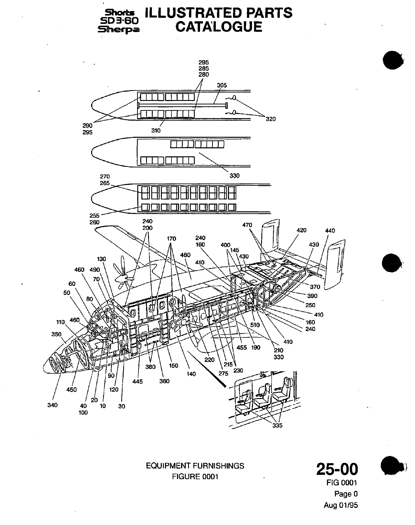
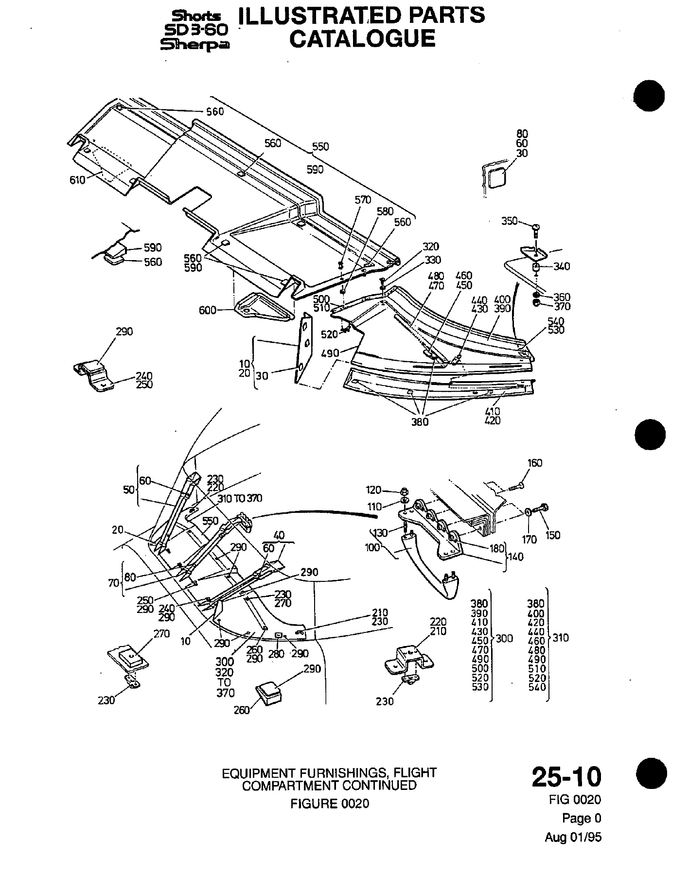
- Chapter 25 – Equipment Furnishings: flight compartment furnishings, pilot and supernumerary seats, pedestal and seat raising mechanism, main cabin bulkheads, sidewall and trim panels, cabin doors, passenger and paratroop seating, forward baggage bay, first aid and medi-vac equipment
- Chapter 26 – Fire Protection: engine fire detection and firewire runs, smoke detection for baggage, cabin and cargo bays, engine fire extinguishers, forward baggage bay and cargo bay extinguisher installations, lance stowage
- Chapter 27 – Flight Controls: aileron controls and aileron trim, rudder and rudder trim, control columns, elevator controls, elevator tab rods, hydraulic flap controls, flap position indication, gust lock and damper
- Chapter 28 – Fuel: forward and rear tank assemblies, ferry fuel system and collector tank, fuel distribution, pressure refuelling, cross feed, gravity feed, tank venting, system drains, contents gauging and low level indication
- Chapter 29 – Hydraulic Power: engine bay hydraulics, spar box and front spar centre wing, stub wing runs, fuselage piping, equipment bay, ground service panel, accumulators, filters, non-return and shut-off valves, hydraulic indication
- Chapter 30 – Ice and Rain Protection: pneumatic de-icing fixed fittings and boots, engine and fuselage de-icing plumbing, air intake anti-icing and actuators, pitot static vent heaters, windshield wipers, heated windshields, rain repellent system, propeller de-icing, ice detector
- Chapter 31 – Indicating and Recording Systems: digital clock, flight data recorder system, centralised warning system and printed circuit board installations
Read end to end, the volume describes the aircraft as a set of replaceable assemblies rather than a set of procedures. The furnishings chapter alone spans cabin trim, cabin doors, passenger seating, paratroop seating and the forward baggage bay, so a single section can take an aircraft from an airline interior layout through to a para-dropping or medi-vac configuration. The flight controls chapters walk the aileron, rudder, elevator and flap runs from the control columns back to the tailplane and outer wing, following every rod, lever, bellcrank, pulley, fairlead and turnbuckle along the way. The fuel and hydraulic chapters work the same way through tank assemblies, refuelling valves, boost pumps, accumulators, filters and service panel connections. Fire protection, ice and rain protection and the indicating and recording chapters close the volume with detection and warning hardware, de-icing boots and plumbing, windshield and pitot heat, wiper and rain repellent assemblies, and the centralised warning panel hardware and circuit boards behind it.
How Each Figure Is Built
Entries are arranged by ATA chapter, then by figure number, then by item number, with the item number matching the callout printed on the illustration. Alongside the item number sits the part number as the manufacturer listed it, followed by the nomenclature and any indented sub-items that make up a larger assembly. Effectivity columns show which aircraft the line applies to, and the units-per-assembly column shows how many are needed per installation rather than per aircraft. That structure matters when a single figure contains both a left-hand and a right-hand variant, or where a line is marked as an alternative to another part number – the catalogue flags both options on the page instead of burying one of them.
What This Volume Is Used For
This is a working document for anyone who has to identify, order, compare or document Shorts SD3-60 Sherpa airframe hardware. Typical uses include rebuilding a cabin interior after a layout change, sourcing paratroop seat fittings, nets, static line and despatch harness hardware, replacing fire detection and extinguishing components in the engine, baggage and cargo bays, tracing a fuel or hydraulic line back to its correct union, clamp, seal or restrictor, sourcing control rod ends, pulleys, fairleads and bearing housings, and confirming which windshield, wiper or de-icing boot assembly belongs to a given airframe. Because every line is anchored to an illustration and an effectivity range, it also serves as a cross-check when a part number has changed, when two suppliers offer alternative items, or when a component is being assessed against a modification standard.
Buying the Right Part Number the First Time
IMAGES PREVIEW
A parts catalogue earns its place on the shelf the moment it saves one wasted order. The Shorts SD3-60 Sherpa Illustrated Parts Catalogue Volume 2 gives you the figure, the callout, the part number, the nomenclature and the quantity in one view, so the person ordering and the person fitting are reading the same line. It supports parts identification, assembly breakdown, alternative-part comparison and effectivity checking, and it keeps the illustrations next to the data instead of separating them. Delivered as an instant PDF download after payment – no shipping, no waiting on a courier, no shelf space. Open it on a laptop in the office, a tablet on the hangar floor or a phone next to the aircraft, and print the figures you need to mark up on the bench.
Reviews
There are no reviews yet.