
Sikorsky UH-60A EH-60A UH-60L Depot Maintenance Work Requirement DMWR 1-1520-237-1 (2007)
Original price was: $42.95.$26.95Current price is: $26.95.
The complete Depot Maintenance Work Requirement for the UH-60A, EH-60A, and UH-60L Black Hawk helicopters. DMWR 1-1520-237-1 covers all airframe depot-level inspection, repair, and overhaul procedures across 180 work packages and over 1,000 pages.
Description
Sikorsky UH-60A EH-60A UH-60L Depot Maintenance Work Requirement DMWR 1-1520-237-1
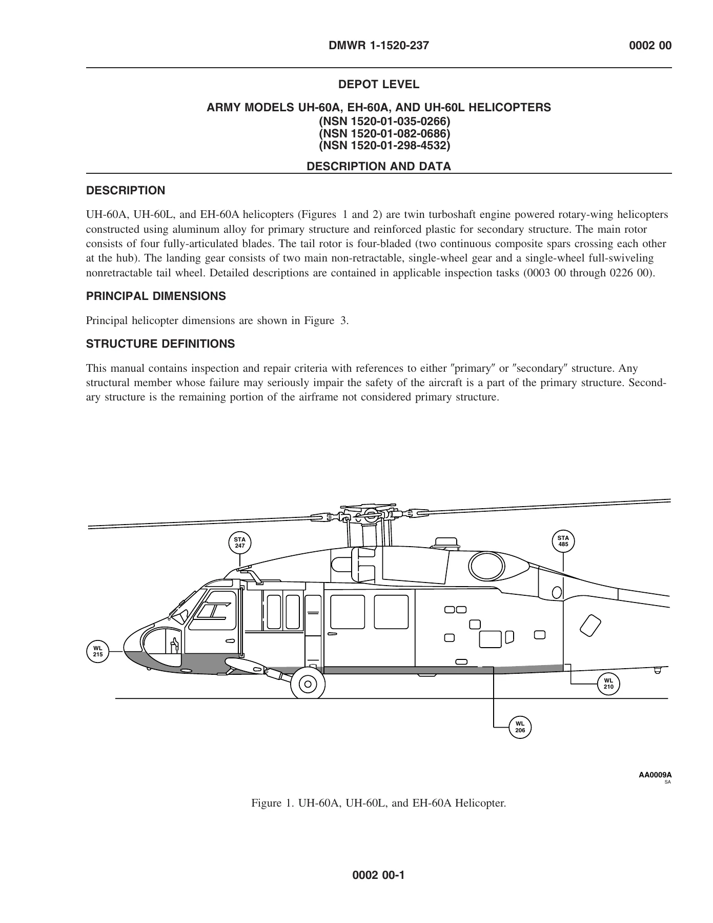
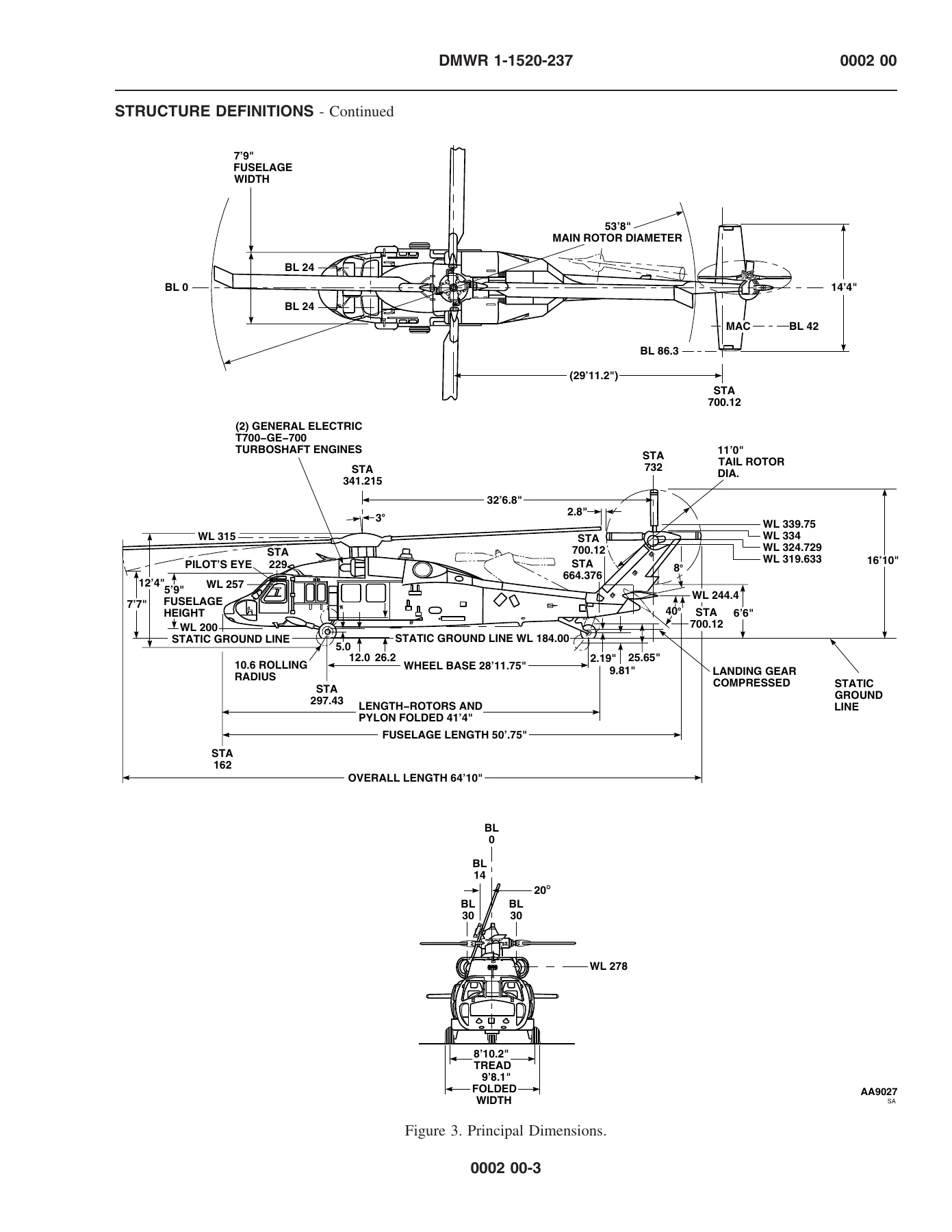
The Sikorsky UH-60A EH-60A UH-60L Depot Maintenance Work Requirement DMWR 1-1520-237-1 is the comprehensive airframe depot-level maintenance standard for the U.S. Army’s UH-60A, EH-60A, and UH-60L Black Hawk helicopters. Published January 15, 2007, this DMWR establishes the requirements for disassembly, cleaning, inspecting, repair, rehabilitation, modification, reassembly, servicing, testing, shipping, and storage of all three helicopter models. The document contains 180 work packages across more than 1,000 pages, making it the most complete single-source reference for depot-level airframe maintenance on these aircraft.
File Details
- Manual Type: Depot Maintenance Work Requirement (DMWR)
- Document Number: DMWR 1-1520-237-1
- Date of Issue: 15 January 2007
- Models Covered: UH-60A, EH-60A, UH-60L
- NSNs: 1520-01-035-0266 (UH-60A), 1520-01-082-0686 (EH-60A), 1520-01-298-4532 (UH-60L)
- Page Count: 1,004 pages
- File Format: PDF
- Language: English
- Distribution: Statement D – authorized to DoD and DoD contractors only due to Critical Technology
What This Manual Covers
This DMWR is organized as a series of 180 work packages that together describe every inspection, repair, and overhaul task required to return a UH-60A, EH-60A, or UH-60L airframe to service. The scope spans the complete aircraft structure and all major systems, from the nose section to the tail rotor pylon.
Structures and Airframe
- Fuselage alignment fixtures – five conditions covering installation of the helicopter in the alignment fixture, servo beam fixture, transmission oil cooler/engine mount fixture, hanger bearing fixtures, and tail cone and tail rotor pylon alignment fixtures
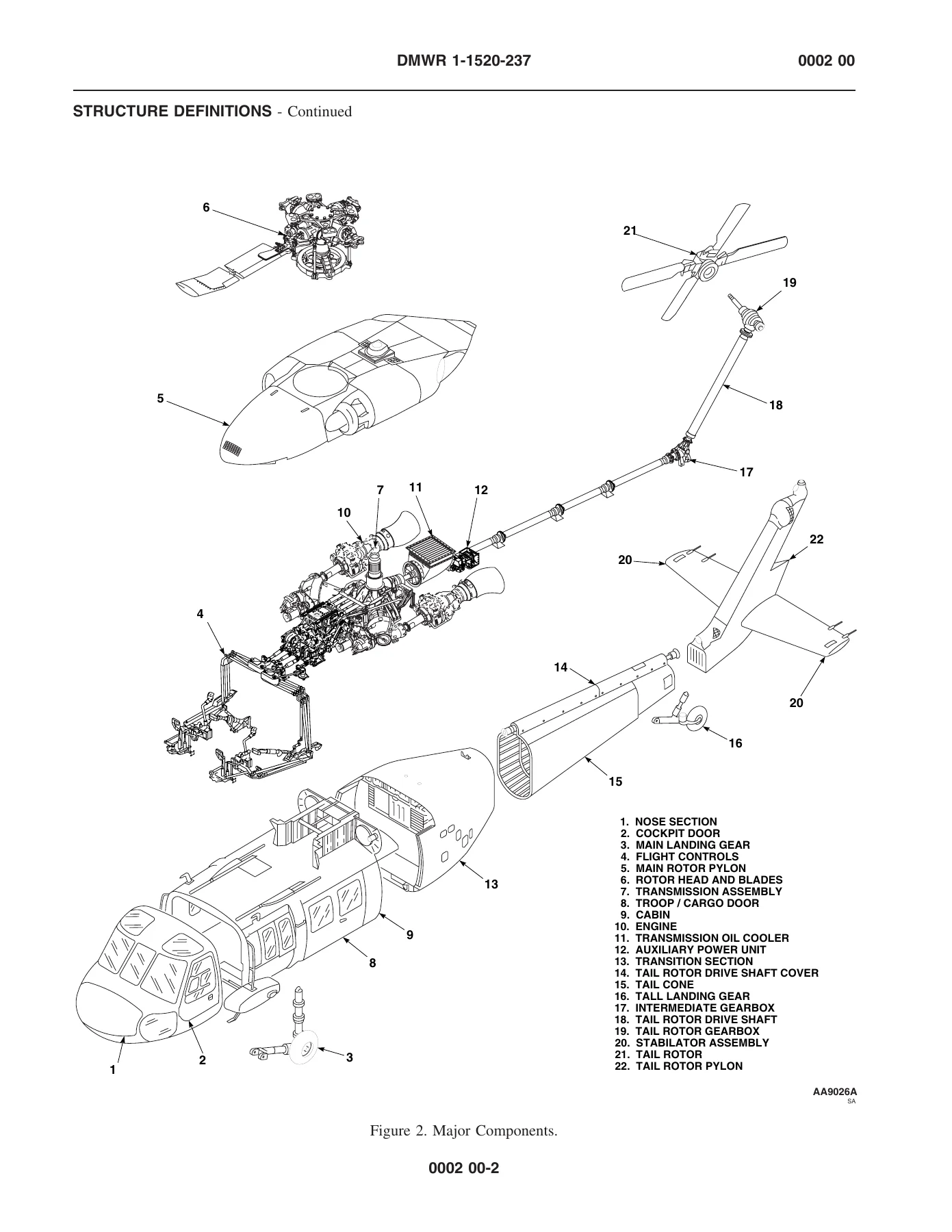
- Nose section, nose tub, cockpit exterior and interior, pilot and copilot seats, main rotor pylon, cabin exterior, front and rear upper cabin frames, cabin tub, cabin interior, transition section, tail cone, tail rotor pylon, and stabilator assembly
- Structural repairs for sheet metal cracks, beaded sections, formed and extruded angles, tees, channels, zees, longerons, frames, formers, ribs, lightening holes, beam caps, skin/frame/stringer combinations, oil canning, rivet short edge distance, aluminum straps, aluminum wire mesh, honeycomb core sandwich panels (aluminum and fiberglass/Kevlar/epoxy skins), composite plastic laminates, adhesive filler, air inlet ducts, engine air inlet diffusers, and HIRSS air duct assemblies
- Weather/water integrity sealing, dissimilar metal insulation, and protective finishes
Rotor Systems
- Main rotor blade and BIM pressure indicator inspection and repair
- Main rotor head assembly – hub, bifilar, damper, spindle, swashplate, and scissor assembly
- Tail rotor installation, tail rotor blade assembly, and outboard retention plate
- Swashplate linkage push rods, flight control link assemblies, forward/aft/lateral bellcrank assemblies, walking beam assembly, bellcrank support assemblies, tie rods, and aft bellcrank support arm
Drive Train
- Main transmission assembly and gust lock
- Shaft and cooler installation – section I drive shaft, axial fan, radiator, hose assemblies
- Tail rotor drive shafts (sections II, III, and IV), viscous dampers, and flexible couplings
- Tail rotor pylon transmission installation – intermediate gear box and tail gear box
- Transmission/gear box chip detectors and temperature sensors
Powerplant and APU
- Engine assembly – rear mount struts and links, front mount support tube, electrical harnesses, fuel system, air and oil lines
- Pneumatic engine starters and pneumatic starter ducting installation
- Auxiliary power unit (APU) and APU start system – hydraulic start motor, self-displacing hydraulic accumulator, APU start valve
- APU generator
IMAGES PREVIEW
Flight Controls and Hydraulics
- Cockpit flight controls – cyclic stick, collective stick, yaw control pedals, control rods, bellcranks, levers
- Cabin flight control rods, bellcranks, and supports
- Flight control mixer assembly
- Flight control cables and pulleys
- Upper deck flight controls shaft installation – directional pushrod, connecting link, torque shaft assemblies, control rods, primary servo rods
- Flight control manifold installation – servo boost manifold, primary servo manifold, first and second stage transfer module manifolds
- Flight control hydraulic installation – yaw trim actuator, roll trim actuator, yaw boost servo, roll SAS actuator, pitch trim assembly, collective boost servo, backup hydraulic pump, utility module, hydraulic pumps, transfer modules, primary servos, pilot-assist servo module, selector valve, hydraulic reservoir, 2nd stage shutoff valve, tail rotor servo
Electrical and Avionics
- General electrical systems – AC and DC power, wiring inspection, splices, bonds, conduit, junctions, relays, switches, circuit breakers
- Retractable landing light and controllable searchlight installation
- External power receptacle
- Exterior and interior lights – position lights, formation lights, utility lights, cockpit flood lights, cabin dome lights, cargo hook infrared lights
- Landing gear switches
- Cargo hook explosive cartridge and electrical housing
- Stabilator electrical system
- Battery installation
- Anti-collision light and power supply
- Primary servo pressure switches
- AC generators
- NVG electrical components
- Automatic flight control system (AFCS) components – SAS amplifier, SAS/FPS computer, stabilator amplifiers, true airspeed transducer, air data transducer, collective stick position sensors, lateral accelerometers
- Communications systems – VHF/FM, VHF/AM, UHF/AM, intercom, IFF
- Navigation systems – VOR/ILS, LF/ADF, doppler, gyromagnetic compass, attitude indicating, rate-of-turn, command instrument
- Missile defense systems – IR jamming transmitter, radar detecting comparator, radar receivers
- Antennas
Fuel, Utility, and Environmental Systems
- Fuel compartment – covers, cells, liners, foam liner
- External fuel system components – pressure and gravity refueling receptacles, prime/boost pump, shutoff valves, breakaway valves, vent valves, selector valves, check valves, tubing, hoses
- Internal fuel system components – quantity probes, boost pumps, interconnect breakaway valve, hi-level shutoff valves, refuel/defuel valves, sump drain valves, check valves, plate assemblies
- Fire extinguisher system – containers, pressure gage, directional control valve
- Fire detection system – control amplifiers and flame sensing detectors
- Blade deice system – OAT sensor, junction box, controller, ice detector, droop stop heaters, sliprings
- Environmental control system – heating/ventilating ducts, blower, mixing valve
- Cargo hook and rescue hoist attachment points
- Infrared (IR) suppressor – module assembly, suppressor core, heat shields, inlet door
- External Stores Support System (ESSS) – HSS beam assembly, beam-to-fuselage fitting, support struts, stores attachment fittings, ejector rack fittings
Instrument Systems
- Instrument panel and glare shield
- Flight instruments, navigation instruments, engine instruments
- Pitot static system
- Air data and airspeed transducers
Corrosion Control
- Cleaning and corrosion control – general surface cleaning (three conditions), corrosion removal and treatment (eleven conditions covering aluminum, magnesium, steel, avionics, electrical switches, relays, circuit breakers, connectors, coaxial connectors, grounding/bonding, antennas, and pitot static tubes)
- Paint removal (stripping) and protective finishes (two conditions)
Chapters Covered
- Chapter 1: General Information, Equipment Description and Data, Theory of Operation
- Chapter 2: Troubleshooting Procedures: General Aircraft Pre-Shop Analysis, Operational Checkout
- Chapter 3: Maintenance Procedures: Fuselage Alignment Fixtures (Conditions I-V), Tail Cone Alignment Fixture, Tail Rotor Pylon Alignment Fixture, Cleaning and Corrosion Control, General Surface Cleaning (Conditions I-III), Corrosion Removal and Treatment (Conditions I-XI), Inspection of Nose Section and Lower Windows, Nose Tub, Cockpit Exterior, Cockpit Interior, Pilot’s/Copilot’s Seats, Main Rotor Pylon, Cabin Exterior, Front Cabin Frame, Rear Upper Cabin Frame, Cabin Tub, Cabin Interior, Transition Section, Tail Cone, Tail Rotor Pylon, Stabilator Assembly, Main Landing Gear, Tail Landing Gear, Engine Assembly, Pneumatic Engine Starters, Main Rotor Blade and BIM Pressure Indicator, Main Rotor Head Assembly, Tail Rotor Installation, Main Transmission Assembly, Shaft and Cooler Installation, Tail Rotor Drive Shafts, Tail Rotor Pylon Transmission Installation, Pneumatic Starter Ducting Installation, Auxiliary Power Unit Start System, Flight Control Manifold Installation, Flight Control Hydraulic Installation, Instrument Systems, Pitot Static System, General Electrical Systems, Retractable Landing Light and Controllable Searchlight Installation, External Power Receptacle, Exterior and Interior Lights, Landing Gear Switches, Cargo Hook Explosive Cartridge and Electrical Housing, Stabilator Electrical System, Battery Installation, Anti-Collision Light and Power Supply, Primary Servo Pressure Switches, Transmission/Gear Box Chip Detectors and Temperature Sensors, APU Generator, AC Generators, NVG Electrical Components, Fuel Compartment, External Fuel System Components, Internal Fuel System Components, Cockpit Flight Controls, Cabin Flight Control Rods/Bellcranks/Supports, Flight Control Mixer Assembly, Flight Control Cables and Pulleys, Upper Deck Flight Controls Shaft Installation, Swashplate Linkage Push Rods, Flight Control Link Assemblies, Flight Control Forward Bellcrank Assembly, Flight Control Aft Bellcrank Assembly, Flight Control Lateral Bellcrank Assembly, Flight Control Walking Beam Assembly, Flight Control Forward Bellcrank Support Assembly, Flight Control Aft Bellcrank Support Assembly, Tail Rotor Directional Quadrant and Spring Capsules, Right and Left Tie Rods, Aft Bellcrank Support Arm, Fire Extinguisher System, Blade Deice System, Fire Detection System, Environmental Control System, Cargo Hook, Rescue Hoist Attachment Points, Auxiliary Power Unit, Infrared (IR) Suppressor, External Stores Support System (ESSS), Air Duct (HIRSS) Main Assembly, First Aid Kits, Automatic Flight Control System (AFCS) Components, Communications Systems, Navigation Systems, Missile Defense Systems, Antennas
- Chapter 4: Maintenance Procedures: Main Landing Gear Hydraulic Brake Lines and Fittings Repair, Engine Drain Lines and Fittings Repair, Hydraulic Lines and Fittings Repair, Pitot-Static Lines and Fittings Repair, Fuel Cell Foam Outer Liner Repair, Fuel Vent and Drain Lines and Fittings Repair, Forward and Aft Link Assemblies Repair (Conditions I-V), Lateral Link Assembly Repair (Conditions I-V), Swashplate Linkage Push Rods Repair (Conditions I-II), Forward Bellcrank Assembly Repair (Conditions I-V), Aft Bellcrank Assembly Repair, Lateral Bellcrank Assembly Repair (Conditions I-IV), Walking Beam Assembly Repair (Conditions I-IV), Forward Bellcrank Support Assembly Repair (Conditions I-III), Aft Bellcrank Support Assembly Repair (Conditions I-II), Left and Right Tie Rods Repair, Aft Bellcrank Support Arm, Fire Extinguishing Lines and Fittings Repair, Environmental Control Lines and Fittings Repair, Cruise Infrared (IR) Suppressor Repairs, Paint Removal (Stripping), Protective Finishes (Conditions I-II), Preparation for Flight Test, Preservation, Packaging, and Marking
- Chapter 5: Maintenance Procedures: Sheet Metal Crack Repair (Conditions I-III), STA 295-308 Beaded Section Repair, Formed or Extruded Angle Repair (Conditions I-II), Tee Repair (Conditions I-III), Channel Repair (Conditions I-III), Zee Repair (Conditions I-III), Longeron Repair (Conditions I-III), Frame Repair, Former Repair, Rib Repair (Conditions I-III), Lightening Hole Repair (Conditions I-II), Tee and Web Repair, Beam Cap Repair, Skin/Frame/Stringer Repair, Stringer Repair (Conditions I-II), Skin/Web/Bulkhead Repair (Conditions I-II), Oil Can Repair (Conditions I-II), Rivet Short Edge Distance Repair, Aluminum Strap Repair (Conditions I-III), Aluminum Strap Repair – Tail Rotor Pylon, Aluminum Wire Mesh Repair (Conditions I-II), Honeycomb Core – Aluminum Skin Sandwich Panel Repair (Conditions I-IV), Honeycomb Core – Fiberglass or Kevlar/Epoxy Skin Sandwich Panels Repair (Conditions I-VII), Composite Plastic Laminate Repair, Composite Plastic Repair Type I (Conditions I-II), Composite Plastic Repair Type II, Composite Plastic Repairs for Misdrilled/Oversize/Elongated/Double Holes, Composite Plastic Repairs for Broken Corner or Tab, Composite Plastic Covered Foam Repairs (Conditions I-II), Adhesive Filler Repair, Air Inlet Duct Repair, Engine Air Inlet Diffuser Repair (Conditions I-II), Box Frame Vibration Absorber Repair, Air Duct (HIRSS) Main Assembly Repair (Conditions I-V), Weather/Water Integrity Sealing (Conditions I-V), Dissimilar Metal Insulation (Conditions I-III), and additional modification and support work packages
- Chapters covering modification work orders, facilities, mobilization requirements, quality assurance, illustrated list of manufactured items, references, modification kit parts lists, special tools, National Stock Number index, Part Number index, expendable and durable items list, tool identification list, mandatory replacement parts, and Critical Safety Item (CSI) listings
Structural Repair Coverage
A significant portion of this DMWR is devoted to structural repair procedures. The manual provides condition-by-condition repair instructions for the airframe’s primary and secondary structure, including sheet metal repairs for cracks, dents, holes, and corrosion; reinforcement and replacement of angles, channels, tees, zees, longerons, frames, formers, and ribs; honeycomb sandwich panel repairs for both aluminum and composite skins; composite plastic laminate repairs; and repair of specialized components like air inlet ducts, HIRSS assemblies, and IR suppressors. Each repair procedure includes material specifications, thickness requirements, fastener callouts, and detailed illustrations.
Critical Safety Item (CSI) warnings appear throughout the manual where specific dimensions, tolerances, finishes, materials, or assembly/inspection procedures must be followed exactly to prevent failure or malfunction. These warnings are a critical part of the document and highlight areas where strict adherence to the DMWR is mandatory.
Corrosion Control and Treatment
The manual includes an extensive eleven-condition corrosion removal and treatment section covering aluminum and magnesium structures, steel components, avionics mounting racks, internal avionics components, electrical switches, relays, circuit breakers, electrical connectors, coaxial connectors, grounding/bonding connectors, antennas, and pitot static tubes. Each condition specifies the cleaning agents, application procedures, and protective coatings required. The document also covers general surface cleaning under three conditions and provides detailed procedures for paint removal and protective finish application.
Who This Manual Is For
This DMWR is written for depot-level maintenance personnel and contractors performing airframe depot maintenance on UH-60A, EH-60A, and UH-60L helicopters. It is a technical working document that establishes the minimum acceptable standards for repair and overhaul. The instructions assume familiarity with aviation maintenance practices and access to the special tools and equipment identified in the manual’s tool lists. Quality assurance and quality control provisions are included to ensure that all work meets the required standards before aircraft are returned to service.
What You Can Do With This Manual
With this DMWR in hand, a qualified technician or depot facility can perform the full range of airframe depot maintenance tasks on UH-60A, EH-60A, and UH-60L helicopters. That includes conducting pre-shop analysis to determine the extent of work required, placing the airframe in alignment fixtures, performing detailed inspections of every structural section and system, executing structural repairs to primary and secondary structure, removing and treating corrosion, applying protective finishes, and preparing the aircraft for flight test and return to service.
The manual’s value lies in its specificity. Rather than general guidance, it provides exact dimensions, tolerances, material specifications, and procedural steps for each task. Following these procedures correctly is essential for maintaining the structural integrity and airworthiness of the aircraft. The repair procedures are illustrated with detailed figures showing damage limits, repair configurations, and fastener layouts, so the technician can see exactly what is required.
The document is delivered as an instant PDF download – no shipping, no waiting. It can be viewed on any device, printed for use in the shop, and used as a reference throughout the maintenance process. Whether you are running a depot maintenance facility, performing contract overhaul work, or maintaining a fleet of these helicopters, this DMWR is the standard reference for airframe depot-level maintenance.
Reviews
There are no reviews yet.