
MD 369FF Maintenance Training Manual – MDHI 369FF Helicopter Systems Course PDF
Original price was: $39.95.$24.95Current price is: $24.95.
The complete 338-page MDHI 369FF Maintenance Training Course (CSP-369FF MTM-1) covering airframe, powertrain, main and tail rotor systems, rigging, engine lubrication and fuel, powerplant, engine controls, electrical, environmental control, instruments and weight and balance.
Description
The MD 369FF Maintenance Training Manual is the full 369FF Maintenance Training Course, identified in its own headers as CSP-369FF MTM-1 and carrying the MD Helicopters, Inc. copyright notice. Across 338 pages and fourteen teaching sections it works through the MDHI 369FF helicopter system by system – the aluminium truss airframe and its crashworthy center beam, the skid landing gear and damper assemblies, the overrunning clutch and main transmission, the static mast and five-blade fully articulated main rotor, the two-blade tail rotor and its control rigging, engine lubrication and fuel supply, the powerplant and its controls, the DC electrical system, heating and ventilating equipment, airframe instruments, and weight and balance.
One point deserves to be stated plainly at the start. The manual’s own caution page declares that it is intended as a training aid only and is not to be used as a handbook while performing maintenance; the applicable Handbook of Maintenance Instructions is the working document for inspections and repairs. This 369FF Maintenance Training Manual is the course that sits behind that work. It explains how each system is constructed, how it operates, how the systems interact, and which dimensions, pressures, rigging points and limits a technician needs to understand before touching the aircraft – which is precisely what turns a set of HMI procedures into something a technician can reason about instead of merely follow.
File Details
- Manual type: Maintenance training manual (systems course)
- Document number: CSP-369FF MTM-1
- Brand: MD Helicopters, Inc. (MDHI)
- Airframe covered: Model 369FF / MD 500 series
- Language: English
- Page count: 338 pages
- File format: PDF
- Copyright notice: 1999-2006 MD Helicopters, Inc.
Chapters Covered
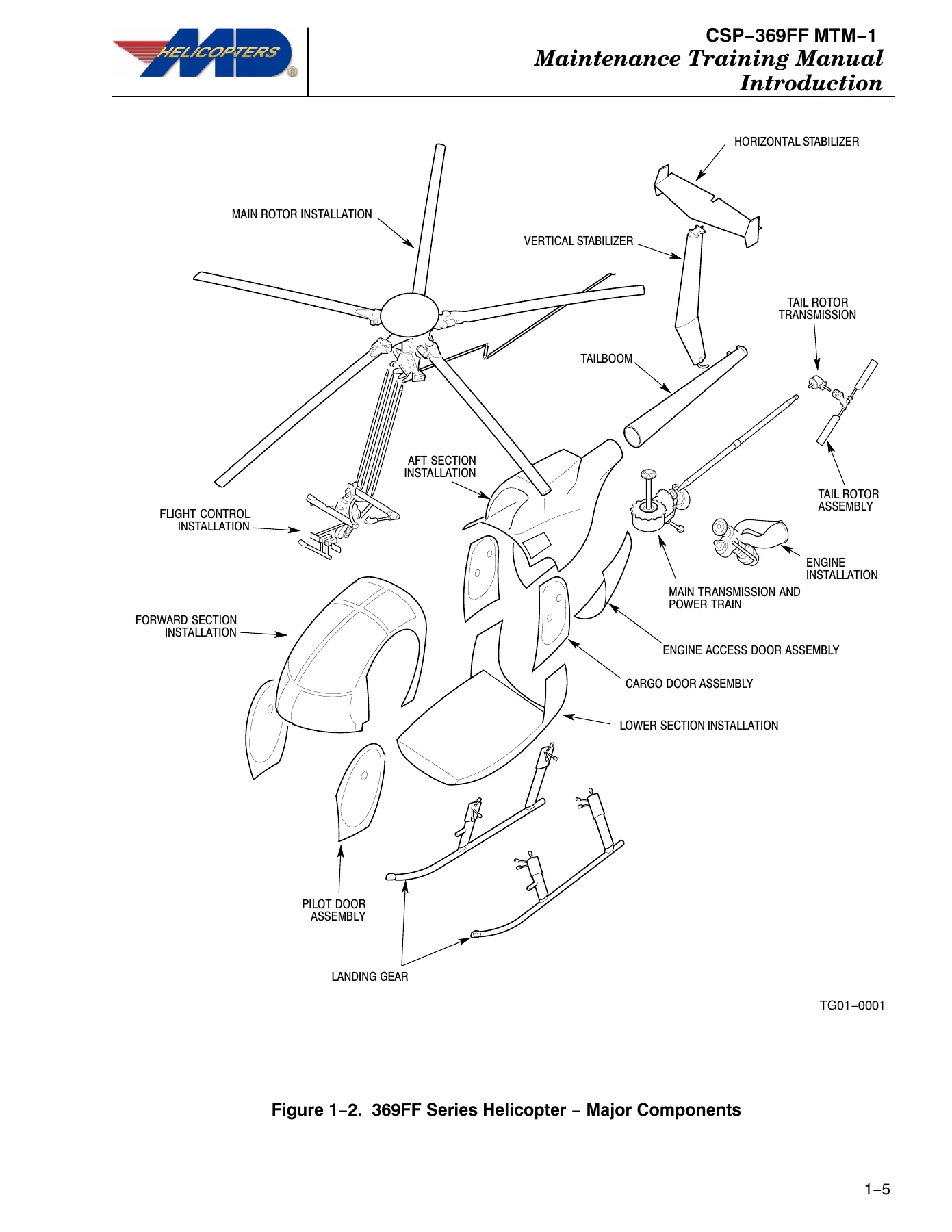
- Section One – Introduction: helicopter design, major components, principal dimensions, publications and the ATA numbering system, service information notices and letters, application of warnings, cautions and notes, Service and Operations Report Form 1601, inspections
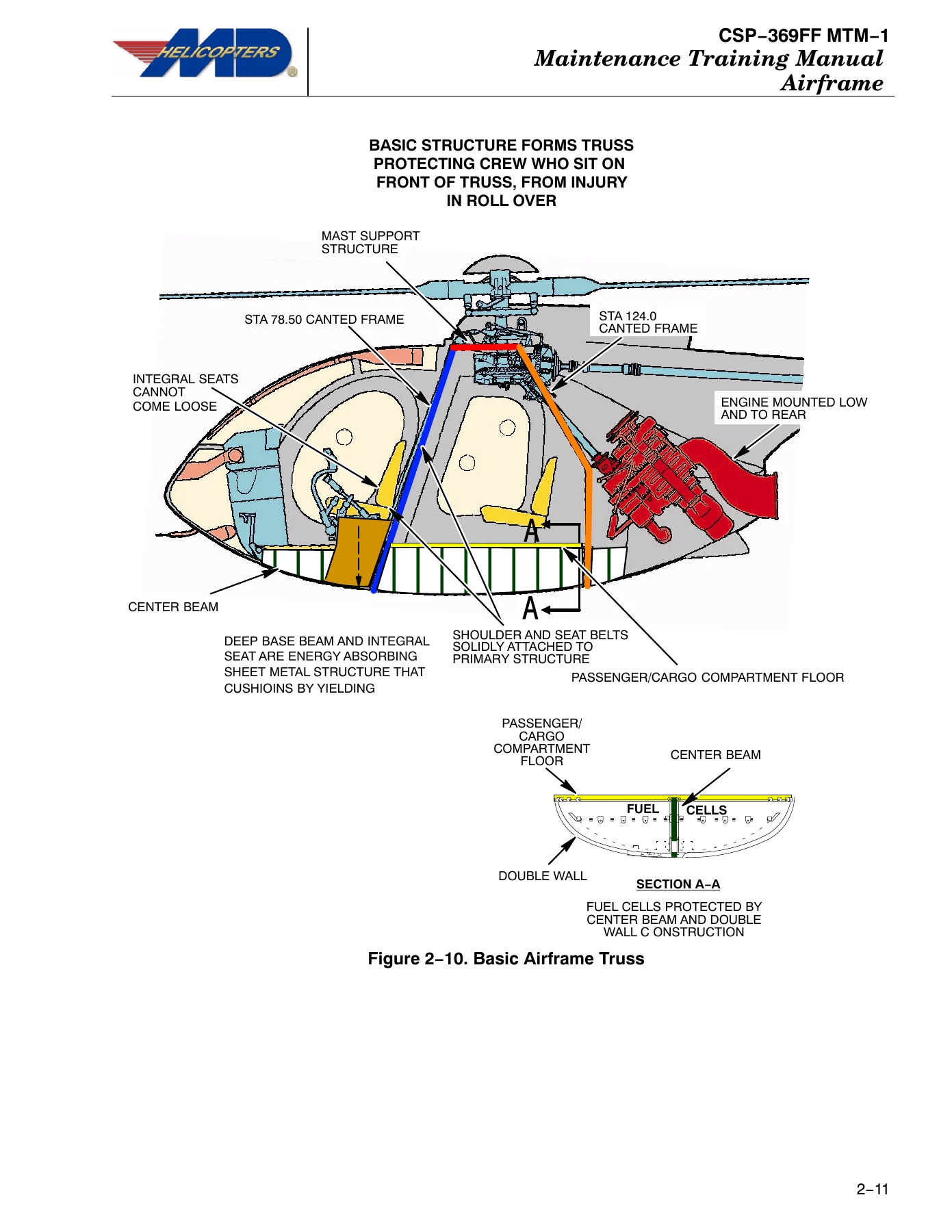
- Section Two – Airframe: airframe station locations, compartments A through H, basic airframe truss, crashworthiness, lower fuselage section, forward fuselage and cockpit enclosure, station 78.50 canted frame, cockpit lower structure, pilot/copilot seat structure, aft fuselage section, station 124.00 canted frame, aft fuselage boom fairing, mast support structure, engine air inlet installation, particle separator filter option, AFS inlet barrier filter, engine mount assembly, engine access doors, tailboom and empennage, vertical and horizontal stabilisers, landing gear and extended landing gear
- Section Three – Powertrain: overrunning clutch and clutch lubrication, main transmission drive shaft and Kamatics (Kaflex) couplings, transmission oil cooler and oil cooler blower assembly, main transmission 369F5100 and 369D25100 with their lubrication systems, pressure pump, scavenge pump, main transmission oil system drain, tail rotor drive shaft and couplings, tail rotor drive shaft damper, tail rotor transmission, rotor brake installation and operation
- Section Four – Tail Rotor and Control Rigging: tail rotor blade, hub and pitch control assembly, anti-torque control system, tail rotor control system, rigging tail rotor controls, tail rotor bungee adjustment
- Section Five – Main Rotor: static mast assembly, main rotor drive shaft, main rotor hub, strap pack, droop stop assembly, pitch housing, blade attaching pins, main rotor damper, main rotor blade
- Section Six – Main Rotor Controls and Rigging: collective pitch controls and friction, collective interconnecting torque tube and collective bungee, cyclic controls and friction, cyclic pitch interconnecting torque tube, cyclic trim actuators, one-way lock, mixer assembly and movement sequence, main rotor swashplate assembly, rotating scissors, rigging the main rotor control system
- Section Seven – Rotor Track and Balance: blade tracking equipment and operation, installation and tracking procedures, trim tabs, balancing, Vibrex balance equipment and operation, dynamic balancing of tail and main rotor, vibration causes, sources and troubleshooting
- Section Eight – Engine Lubrication and Fuel Systems: engine oil pump and internal distribution, airframe oil system, lubricant type and specification data, oil foaming and pressure fluctuations, lubrication system servicing and preoiling, fuel supply system, fuel cell vent system, fuel shutoff control and valve, fuel supply lines, Sunstrand and TRW fuel pumps, fuel filter assembly, fuel quantity indicating system, fuel types and usage, fuel system maintenance
- Section Nine – Powerplant: compressor, combustion section, turbine, power and accessories gearbox, engine instruments, warning and caution lights, engine power out and low rotor RPM warning, automatic reignition, anti-ice system, exhaust system, engine mounts
- Section Ten – Engine Controls: fuel control system, gas producer fuel control and linkage, rigging gas producer controls, power turbine governor and rigging
- Section Eleven – Electrical System: basic electrical components, external power receptacle, battery/external power switch, voltage regulator, overvoltage relay, reverse current relay, start relay, starter-generator, nickel cadmium battery, generic wire harness, generator control unit, indicator lights dimmer, starting and generating system troubleshooting
- Section Twelve – Environmental Control Systems: heating and defogging system, heater control valve and cable, ventilating system and vent valve control
- Section Thirteen – Airframe Instruments: engine and powertrain instruments, navigation instruments, airspeed indicator, altimeter, elapsed time and digital clocks, OAT indicator, pitot static system and heated pitot tube option
- Section Fourteen – Weight and Balance: weight and balance procedures, leveling target position, reference datum and jig point location, balance diagram
What makes this course useful rather than merely descriptive is the way each section moves from construction to operation to the numbers that matter. The airframe chapters do not just name the station 78.50 and station 124.00 canted frames – they explain how the center beam, canted frames, mast support and cargo floor lock together into a truss that carries static and dynamic loads and yields progressively in a crash. The powertrain chapters separate the two main transmission variants and follow the oil from pressure pump through cooler, thermostatic bypass valve and 12 micron filter before it reaches the gearbox passages. The rotor chapters explain why the strap pack allows centrifugal load from one blade to be reacted by the opposite blades, and why that strap pack is not field maintainable. The controls and rigging chapters give the actual bellcrank dimensions, swashplate rigging tool procedure and bungee adjustment logic. Section Seven walks through the interrupter spacing that lets five blade images be read in order of rotation, then into balancing charts, IPS readings, clock angle and vibration frequency ranges with their likely causes. Sections Eight through Ten follow the engine from dry-sump lubrication and fuel cell venting through the gas producer fuel control to the power turbine governor linkage.
Airframe and Structural Systems
Section Two is the longest teaching block in the MD 369FF Maintenance Training Manual. It defines the station, butt and water line reference system used throughout the aircraft, then breaks the fuselage into its eight lettered compartments and each major structural assembly. You get the center beam with its landing gear forgings and cargo hook fittings, the cargo floor with its hat channels and stressed access covers, the jacking fittings, the bulkheads, the cockpit enclosure and windshield assemblies, the door latching and safelocking mechanism, the station 78.50 and station 124.00 canted frames with the upper and lower firewalls, the mast support structure and its fail-safe attachment, the engine air inlet fairing, the AFS inlet barrier filter and particle separator options, the engine mount assembly, the tailboom, vertical and horizontal stabilisers, and both the standard and extended landing gear with struts, braces, fairings and nitrogen-charged dampers.
Powertrain, Transmissions and Rotor Systems
Section Three follows torque from the engine output pad through the overrunning clutch, the Kamatics drive shaft, the oil cooler blower, the main transmission and out to both rotors. The two transmission part numbers are treated separately because their lubrication systems and internal layouts differ, and the chapter covers the pressure pump, scavenge pump, chip detectors, oil pressure and temperature switches, and the externally mounted cooler with its bypass valves. Sections Four, Five and Six then cover the tail rotor pitch control assembly and hub shimming, the static mast and main rotor hub with the lower shoe, droop stop ring and followers, the strap pack and pitch housings, the elastomeric main rotor dampers, the main rotor blade construction, and the full flight control chain from collective and cyclic sticks through the mixer assembly to the swashplate and rotating scissors.
Engine, Fuel, Electrical and Environmental Systems
The later sections carry the systems knowledge. Engine lubrication is covered from the gear-type pressure pump and its 115-130 psi regulated system through internal oil distribution to the torquemeter and every numbered bearing, followed by the airframe oil tank, oil cooler, thermostatic bypass valve, drain routing and the Type 1 and Type 2 lubricant specifications with their mixing restrictions. The fuel chapters cover the two interconnected cells, vent system with emergency shutoff valve, shutoff control rigging, both fuel pump designs, the 5 micron filter assembly with its differential pressure indicator, and fuel quantity indicating calibration. Section Nine covers the engine itself, its instruments, the warning and caution light logic, the engine power out warning, automatic reignition and the anti-ice system. Section Eleven explains the DC system, the nickel cadmium battery’s very different servicing rules, the generic wire harness versions and generator control unit, with a troubleshooting table. Sections Twelve and Thirteen cover heating, defogging and ventilation, the airspeed indicator, altimeter, clocks, OAT indicator and the pitot static system.
Rigging, Tracking, Balancing and Vibration Work
For anyone who actually turns wrenches, the rigging and vibration material is the heart of the course. Tail rotor rigging is given with the bellcrank measurements at stations 95 and 142, the swashplate rigging tool procedure, pedal stop adjustment and bungee spring tuning. Main rotor rigging covers control rod end bearing adjustment to the nearest half turn, cyclic neutral positions, the collective rigging fixture and a field rigging aid drawing with its dimensions. Tracking walks through ground tracking, hover verification, forward flight tracking and autorotation RPM adjustment, trim tab bending effects on drag and centre of pressure, and the balance chart method for reading amplitude and clock angle. The vibration chapter classifies low, medium and high frequency ranges, ties each to the rotating components that can cause it, and lists the specific checks for tail rotor, engine, powertrain and control feedback vibrations.
What This 369FF Course Lets You Do
IMAGES PREVIEW
With this MD 369FF Maintenance Training Manual on hand you can study the whole aircraft in a structured order – how the truss carries flight and landing loads, how torque reaches two rotors through clutch, shafts and gearboxes, how the static mast isolates primary flight loads from the transmission, how the strap pack, droop stops, dampers and pitch housings work together, how fuel and oil move through the airframe, and how the flight controls are rigged and re-rigged after linkage replacement. You can prepare for type training or refresher study, brief a new technician on a system before a task, interpret a vibration complaint against the frequency ranges the course lays out, and check that a rigging or adjustment figure you are about to use is the right one for the transmission and engine variant installed. Understanding the system behind the procedure is what separates a repair that lasts from one that comes back, and this course is built specifically to build that understanding for the 369FF. Delivery is instant – a downloadable PDF with no shipping, readable on a laptop, tablet or phone, and printable page by page or as a complete reference set for the hangar shelf.
Reviews
There are no reviews yet.