★ TRUSTED BY 321,897+ PROFESSIONALS WORLDWIDE
🏢
Trusted Business
Verified & Licensed
🛡️
Virus Free Files
100% Safe Downloads
🔒
Secure Payment
SSL Protected
Instant Delivery
Available Immediately
Sale!

Hughes OH-6A Cayuse Helicopter Aviation Unit and Intermediate Maintenance Manual TM 55-1520-214-23

Original price was: $39.95.Current price is: $24.95.

Comprehensive technical manual TM 55-1520-214-23 providing Aviation Unit Maintenance (AVUM) and Aviation Intermediate Maintenance (AVIM) instructions, servicing standards, overhaul schedules, and airframe structural repair data for the Hughes OH-6A Cayuse observation helicopter.

Instant PDF Download
Available immediately
💾
Save to Your Device
Download & keep forever
🛡️
Antivirus Scanned
100% virus-free
🌍
Trusted Worldwide
175,000+ customers

Description

This technical publication serves as the official Aviation Unit Maintenance (AVUM) and Aviation Intermediate Maintenance (AVIM) manual for the Hughes OH-6A Cayuse Helicopter, designated under Department of the Army technical manual TM 55-1520-214-23 (incorporating updates through Change 39). Covering airframe assemblies, dynamic drive components, mechanical flight controls, turboshaft powerplant installations, and electrical distribution networks, this manual gives aviation mechanics and maintenance personnel complete depot- and field-level servicing, inspection, and repair instructions.

File Details

  • Manual Type: Aviation Unit and Intermediate Maintenance Manual (AVUM & AVIM)
  • Brand: Hughes Helicopters / Department of the Army
  • Model: OH-6A Cayuse Observation Helicopter (Series 1, Series 2, and Series 3)
  • Document Number: TM 55-1520-214-23
  • Publication Date: 31 December 1976 (Includes Changes 1 through 39 updated through November 1992)
  • Language: English
  • Format: Digital PDF
  • Applicable Engines: Allison T63-A-5A / T63-700 Turboshaft Series

Comprehensive Technical Scope & Aircraft Systems

The Hughes OH-6A Cayuse Helicopter Aviation Unit and Intermediate Maintenance Manual TM 55-1520-214-23 details extensive procedures across all structural and mechanical boundaries of the aircraft. Clear mechanical breakdowns, dimensional limits, and rigging standards ensure precision maintenance for the four-bladed fully articulated main rotor group, offset flapping hinges, drive shafts, overrunning clutches, and the two-bladed anti-torque tail rotor system.

Complete PDF Bookmark Tree

Complete Bookmarks

The complete bookmarks in the “Hughes OH-6A Cayuse Helicopter Aviation Unit and Intermediate Maintenance Manual TM 55-1520-214-23” are as follows:

Parts Manual
Maintenance Manualp. 1
Changesp. 2
Change 39p. 2
Change 38p. 3
Change 37p. 4
Change 36p. 6
Change 35p. 7
Change 34p. 8
Change 33p. 9
Change 32p. 10
Change 31p. 11
Change 30p. 12
Change 29p. 13
Change 28p. 14
Change 27p. 17
Change 26p. 18
Change 25p. 19
Change 24p. 20
Change 23p. 21
Change 22p. 22
Change 21p. 23
Change 20p. 25
Change 19p. 26
Change 18p. 27
Change 17p. 28
Change 16p. 29
Change 15p. 30
Change 14
Change 13p. 32
Change 12p. 33
Change 11p. 34
Change 10p. 35
Change 9p. 36
Change 8p. 37
Change 7p. 38
Change 6p. 39
Change 5p. 41
Change 4p. 42
Change 3p. 43
Change 2p. 44
Change 1p. 45
Warning Pagep. 46
Table of Contentsp. 50
Prefacep. 52
Major Componentsp. 53
Ch. 1 AIRCRAFT GENERALp. 56
I – Servicingp. 56
Fig. 1-1 Servicing Pointsp. 57
Table 1-1 Consumable Maintenance Supplies and Materialsp. 66
Table 1-1 Consumable Maintenance Supplies and Materials (con't)p. 67
Table 1-2 National Supply Class Referencep. 72
Table 1-3 Special Tools and Test Equipmentp. 73
Table 1-3 Special Tools and Test Equipment (con't)p. 74
Table 1-4 Support Equipmentp. 74
II – Lubricationp. 75
III – Handling, Jacking, Mooring, Hoisting and Sling Loadingp. 75
Table 1-5 Premaintenance Requirements for General Handling of Aircraftp. 75
Fig. 1-2 Principal Dimensionsp. 76
Fig. 1-3 Hoisting, Jacking and Levelingp. 77
Fig. 1-4 Main Rotor Maintenance Platformp. 78
Fig. 1-5 Folding and Stowing of Main Rotor Bladesp. 79
Fig. 1-6 Ground Handling Wheelsp. 82
Fig. 1-7 Servicing Main Rotor Bladesp. 84
Table 1-6 Approximate Hoisting Weights of Componentsp. 85
IV – Inspection Requirementsp. 86
Fig. 1-8 Area Diagramp. 87
Aircraft Inspection Checksheetp. 88
V – Overhaul and Retirement Schedulep. 107
Table 1-7 Overhaul and Retirement Schedulep. 108
Table 1-7 Overhaul and Retirement Schedule (con't)p. 109
Ch. 2 AIRFRAMEp. 110
Section I – Fuselagep. 110
Fig. 2-1 Access and Inspection Provisionsp. 111
Fig. 2-2 Access and Inspection Provisions (Crash-resistant Fuel System)p. 118
Fig. 2-3 Engine Access Doorsp. 125
Fig. 2-4 Engine Access Doors (Series 3 Aircraft)p. 126
Fig. 2-5 Engine Access Doors for Aircraft with Upward Exhaustsp. 127
Fig. 2-6 Pilot and Cargo Doorsp. 130
Fig. 2-7 Door Locking Devicesp. 131
Fig. 2-8 Pilot and Cargo Door Detailsp. 133
Fig. 2-9 Pilot and Cargo Door Jettison Mechanismp. 135
Fig. 2-10 Sound Insulation Blanketsp. 139
Fig. 2-11 Seats and Seat Armorp. 142
Fig. 2-12 Repair Limits for Troop Seat Bracketsp. 146
Fig. 2-13 Seat Belt, Shoulder Harness, and Crash Padsp. 147
Fig. 2-14 Inertia Reel and Manual Controlp. 149
Fig. 2-15 Canopy and Window Serviceability Criteriap. 154
Fig. 2-16 Canopy Installationp. 155
Fig. 2-17 Aft Compartment Window Installationp. 157
Fig. 2-18 Typical Laminated Fiberglass Repairp. 161
Fig. 2-19 Body Group Sectionsp. 163
Fig. 2-20 Body Group major Structural Sectionsp. 164
Fig. 2-21 Station Diagramp. 166
Fig. 2-22 Support of Disassembled Aircraftp. 167
Fig. 2-23 Skin Plating Diagramp. 168
Table 2-1 Highly-Stressed Structural Fittingsp. 169
Fig. 2-24 Body Group Fittingsp. 170
Fig. 2-25 Center Beam Repairp. 176
Table 2-2 Premaintenance Requirements for Removal and Installation of Landing Gear Bearingsp. 178
Fig. 2-26 Center Beam Fitting Bearing Replacementp. 179
Fig. 2-27 Landing Gear Fitting Temporary Repairp. 180
Fig. 2-28 NCR Fuel Cell Support Skin Installationp. 181
Fig. 2-29 CR Fuel Cell Support Installationp. 182
Fig. 2-30 Firewall Installationp. 186
Fig. 2-31 Typical Aft Section Firewell Repairp. 187
Fig. 2-32 Typical Engine Compartment Rib Repairp. 188
Fig. 2-33 Station 124.00 Canted Frame Patch Repair (1 of 2)p. 190
Fig. 2-33 Station 124.00 Canted Frame Patch Repair (2 of 2)p. 191
Fig. 2-34 Aft Bulkhead Channel Repairsp. 192
Fig. 2-35 Tail Rotor Drive Shaft Fairing Repair and Replacementp. 193
Fig. 2-36 Position Light Support Repairp. 195
Fig. 2-37 Mast Support Structurep. 196
Fig. 2-38 Boom Fairing Repairsp. 198
Section II – Empennagep. 200
Table 2-3 Structural Repair Materialsp. 201
Table 2-4 Standard Stock Structural Repair Materialsp. 202
Fig. 2-39 Extruded Angle, Equal Leg, Aluminum Alloyp. 203
Fig. 2-40 Extruded Angle, Unequal Leg, Aluminum Alloyp. 204
Fig. 2-41 Extruded Tee, Aluminum Alloyp. 205
Fig. 2-42 Extruded Tee, Bulb, Aluminum Alloyp. 205
Fig. 2-43 Extrusion, Aluminum Alloyp. 206
Fig. 2-44 Extruded Tee, Bulb, Aluminum Alloyp. 206
Fig. 2-45 Extruded Open Angel, Aluminum Alloyp. 207
Fig. 2-46 Tee, Bulb, Unequal Thicknessp. 208
Fig. 2-47 Extrusion, Aluminum Alloyp. 208
Fig. 2-48 Extruded Open Angle, Unequal Legs and Thicknessp. 209
Fig. 2-49 Extrusion, Aluminum Alloyp. 210
Fig. 2-50 Tee, Bulb, Equal Thicknessp. 210
Fig. 2-51 Extrusion, Magnesiump. 211
Fig. 2-52 Extrusion, Aluminum Alloyp. 212
Fig. 2-53 Extrusion, Tee, Unequal Legs, Aluminum Alloyp. 212
Fig. 2-54 Extrusion, Unequal Legsp. 213
Fig. 2-55 Extruded Open Angle, Equal Thickness Legsp. 214
Fig. 2-56 Extruded Tee, Unequal Legsp. 214
Fig. 2-57 Extruded Tee, Unequal Legsp. 215
Fig. 2-58 Extruded Channelp. 215
Fig. 2-59 Tail Surfaces (Empennage)p. 216
Fig. 2-60 Tailboom Assemblyp. 219
Fig. 2-61 Typical Tailboom Skin Patch Repairp. 220
Fig. 2-62 Tailboom Frame and Gusset Repairp. 221
Fig. 2-63 Tailboom Fittingsp. 223
Fig. 2-64 Wire Strike Protection Systemp. 225
Fig. 2-65 WSPS Parts Replacement (1 of 4)p. 235
Fig. 2-65 WSPS Parts Replacement (2 of 4)p. 236
Fig. 2-65 WSPS Parts Replacement (3 of 4)p. 237
Fig. 2-65 WSPS Parts Replacement (4 of 4)p. 238
Ch. 3 ALIGHTING GEARp. 239
Section I – Skids and Strutsp. 239
Table 3-1 Premaintenance Requirements for Removal of Landing Gearp. 239
Fig. 3-1 Landing Gearp. 240
Fig. 3-2 Landing Gear (Lockbolt-mounted skids) Repair and Replacementp. 241
Fig. 3-3 Landing Gear (Machine bolt-mounted skids) Repair and Replacementp. 242
Table 3-2 Maximum Damage Limits for Landing Gear Componentsp. 244
Table 3-3 Premaintenance Requirements for Removal and Installation of Skidsp. 245
Fig. 3-4 Skid Tube Structural Repairp. 247
Table 3-4 Premaintenance Requirements for Damper Extension Checkp. 248
Table 3-5 Damper Extension Checkp. 248
Fig. 3-5 Landing Gear Damper Inspection Methodsp. 249
Fig. 3-6 Landing Gear Damper (Bladder-type) Reference Markingsp. 250
Table 3-6 Premaintenance Requirements for Damper Removal and Installationp. 250
Fig. 3-6A Locally Fabricated Toolsp. 252
Fig. 3-6B Use of Locally Fabricated Toolsp. 253
Fig. 3-6C Poppet-Type Damper Assembly – Exploded and Section Views (1 of 2)p. 254
Fig. 3-6C Poppet-Type Damper Assembly – Exploded and Section Views (2 of 2)p. 255
Table 3-7 Detailed Inspection After Cleaningp. 258
Table 3-7 Detailed Inspection After Cleaning (cont.)p. 259
Fig. 3-6D Minor Repair – Barrel and Lower Cap Assemblyp. 260
Table 3-8 Part No. 369A6350 Damper Assembly Fluid Levelp. 261
Table 3-9 Part No. 369A6350 Damper Assembly Nitrogen Gas Pressurep. 264
Fig. 3-6E Torque Stripe and Decal/Plate Requirementsp. 266
Fig. 3-7 Landing Gear Fairing – Repair and Replacementp. 267
Ch. 4 POWER PLANTp. 271
Section I – Generalp. 271
Section II – Power Plantp. 271
Table 4-1 Troubleshooting of the Enginep. 272
Table 4-2 Premaintenance Requirements for Removal of the Enginep. 273
Fig. 4-1 Engine Disconnect/Reconnect Points (1 of 2)p. 274
Fig. 4-1 Engine Disconnect/Reconnect Points (2 of 2)p. 277
Fig. 4-2 Engine Accessory Replacement (1 of 2)p. 278
Fig. 4-2 Engine Accessory Replacement (2 of 2)p. 279
Table 4-3 Premaintenance Requirements for Removal of Accessoriesp. 280
Table 4-4 Premaintenance Requirements for Installation of Accessoriesp. 281
Table 4-5 Premaintenance Requirements for Installation of the Enginep. 284
Fig. 4-2A OH-6 Accumulator Double Check Valve Installation (1 of 2)p. 285
Fig. 4-2A OH-6 Accumulator Double Check Valve Installation (2 of 2)p. 286
Fig. 4-3 Engine Mounts and Fittingsp. 290
Table 4-6 Premaintenance Requirements for Removal of Lower Engine Mountsp. 291
Table 4-7 Premaintenance Requirements of Installation of Upper Engine Mountsp. 292
Fig. 4-4 Engine Armor Kit Installationp. 294
Table 4-8 Premaintenance Requirements for Engine-to-Transmission Alignmentp. 296
Fig. 4-5 Engine-to-Transmission Alignment Checkp. 297
Section III – Cooling Systemp. 298
Fig. 4-6 Engine Cooling System Installationp. 299
Section IV – Air Induction Systemp. 300
Fig. 4-7 Air Induction System (1 of 2)p. 301
Fig. 4-7 Air Induction System (2 of 2)p. 302
Fig. 4-8 Rework of Replacement Filter Elements (1 of 2)p. 303
Fig. 4-8 Rework of Replacement Filter Elements (2 of 2)p. 304
Fig. 4-9 Simplified Schematic of Inertial Particle Separator Air Filterp. 305
Fig. 4-10 Cold Weather Heat Tube Installationp. 306
Fig. 4-11 Air Induction System Componentsp. 308
Table 4-9 Premaintenance Requirements for Testing Barrier Filter Pressure Switchp. 310
Table 4-10 Troubleshooting of the Filter Bypass Air Indicator Systemp. 310
Fig. 4-12 Barrier Filter Bypass Air Control Installationp. 312
Fig. 4-13 Inertial Particle Separator Air Filter Assemblyp. 314
Fig. 4-14 Bypass Air Control Installation, Inertial Particle Separator Air Filter (1 of 2)p. 317
Fig. 4-14 Bypass Air Control Installation, Inertial Particle Separator Air Filter (2 of 2)p. 318
Fig. 4-15 Engine Anti-icing Valve Control Cablep. 322
Table 4-11 Troubleshooting of the Anti-icing Control Systemp. 323
Section V – Exhaust Systemp. 324
Fig. 4-16 Exhaust Systemsp. 325
Section VI – Oil Systemp. 327
Table 4-12 Troubleshooting of the Engine Oil Systemp. 328
Table 4-12 Troubleshooting of the Engine Oil System (con't)p. 329
Fig. 4-17 Engine Oil Tank (Unarmored Aircraft)p. 330
Fig. 4-18 Engine Oil Tank (Armored Aircraft)p. 331
Fig. 4-19 Engine Oil Supply System Schematic (Armored Aircraft)p. 332
Table 4-13 Premaintenance Requirements for Removal of Oil Coolerp. 335
Fig. 4-20 Oil Cooler and Duct Assemblyp. 336
Fig. 4-21 Oil Cooler Cleaning Setupp. 337
Table 4-14 Premaintenance Requirements for Installation of Oil Coolerp. 338
Table 4-15 Premaintenance Requirements for Removal of the the Oil Supply System Drain Valve and Check Valvep. 338
Table 4-16 Premaintenance Requirements for Installation of the Oil System Drain Valve and Check Valvep. 339
Fig. 4-22 Oil Cooler Bypass Valve Test Setupp. 340
Fig. 4-23 Engine Oil Pressure Sender and Chip Detectorp. 342
Section VII – Power Controlsp. 343
Fig. 4-24 Engine Power Controls Systemp. 344
Table 4-17 Troubleshooting of the Power Controlsp. 345
Fig. 4-25 Gas Producer Controls Riggingp. 346
Fig. 4-26 Power Turbine Governor Controls Rigging (1 of 2)p. 348
Fig. 4-26 Power Turbine Governor Controls Rigging (2 of 2)p. 349
Fig. 4-27 Gas Producer Control Linkage Disassemblyp. 352
Fig. 4-28 Governor Control Linkage (Fwd of Engine Compartment) Disassemblyp. 354
Fig. 4-29 Governor Control Linkage (Engine Component) Disassemblyp. 355
Fig. 4-30 N2 Trim Actuator Test Hookupp. 357
Section VIII – Ignition Systemp. 358
Table 4-18 Premaintenance Requirements for Maintenance of the Ignition Systemp. 358
Fig. 4-31 Automatic Restart System (1 of 2)p. 359
Fig. 4-31 Automatic Restart System (2 of 2)p. 360
Table 4-19 Troubleshooting of the Engine Automatic Restart Systemp. 362
Section IX – Quick Change Assemblyp. 363
Ch. 5 ROTORSp. 365
Section I – Main Rotor Hub and Bladesp. 365
Section II – Main Rotor Hubp. 365
Fig. 5-1 Main Rotor Hub and Bladesp. 366
Table 5-1 Troubleshooting the Main Rotor Hub and Bladesp. 367
Table 5-2 Premaintenance Requirements for Removal of Main Rotor Hubp. 368
Fig. 5-2 Main Rotor Hub Installationp. 369
Fig. 5-3 Main Rotor Mast Locknut Installationp. 370
Fig. 5-4 Pulling Hub Asembly Off Mastp. 371
Fig. 5-5 Hub Assembly Cross Section (1 of 2)p. 372
Fig. 5-5 Hub Assembly Cross Section (2 of 2)p. 373
Fig. 5-6 Strap Pack Lamination Inspection (1 of 2)p. 375
Fig. 5-6 Strap Pack Lamination Inspection (2 of 2)p. 376
Fig. 5-7 Main Rotor Hub Component Repair (1 of 2)p. 377
Fig. 5-7 Main Rotor Hub Component Repair (2 of 2)p. 378
Fig. 5-8 Droop Stop Repairp. 382
Table 5-3 Premaintenance Requirements for Installation of Main Rotor Headp. 383
Table 5-4 Premaintenance Requirements for Droop Angle Inspectionp. 387
Table 5-5 Premaintenance Requirements for Checking Damper Torquep. 388
Fig. 5-9 Rotor Blade Damper Assemblyp. 389
Table 5-6 Premaintenance Requirements for Damper Adjustment, Phasing and Reassemblyp. 391
Fig. 5-10 Damper Torque and Phasing Adjustmentp. 392
Section III – Main Rotor Bladesp. 393
Fig. 5-11 Main Rotor Blade Assemblyp. 394
Table 5-7 Blade Tracking Summary Procedurep. 395
Table 5-8 Premaintenance Requirements for Tracking Main Rotor Bladesp. 395
Fig. 5-12 Typical Track Conditions and Adjustmentp. 396
Fig. 5-13 Main Rotor Blade Tracking Strobe Installationp. 397
Table 5-9 Premaintenance Requirements for Blade Track Adjustmentp. 398
Fig. 5-14 Blade Tab Angle Adjustmentp. 400
Table 5-9A Premaintenance Requirements for Balancing Main Rotor Hub and Bladesp. 402
Table 5-9B Main Rotor Balancing Hardwarep. 403
Fig. 5-14A Main Rotor Blade Balance Equipment Installationp. 404
Table 5-10 Autorotation Rpm Chartp. 405
Fig. 5-15 Main Rotor Blade Normal Damage and Repair Limits for Scratches, Gouges and Nicksp. 406
Fig. 5-16 Main Rotor Blade Normal Damage and Repair Limits for Dents and Depressionsp. 408
Fig. 5-16A Inspection and Repair Main Rotor Blade Metal Abrasion Stipp. 409
Fig. 5-17 Main Rotor Blade Restricted Service Damage and Repair Limits (1 of 2)p. 412
Fig. 5-17 Main Rotor Blade Restricted Service Damage and Repair Limits (2 of 2)p. 413
Table 5-11 Premaintenance Requirements for Main Rotor Blade Repairp. 414
Fig. 5-18 Restricted Service Life Blade Repairp. 416
Fig. 5-19 Vibration Absorberp. 420
Section IV – Main Rotor Controlsp. 421
Section V – Tail Rotor and Control Systemp. 421
Table 5-13 Premaintenance Requirements for Removal of Tail Rotor Assemblyp. 421
Fig. 5-20 Tail Rotor Installationp. 423
Fig. 5-21 Tail Rotor and Pitch Control Assembliesp. 424
Table 5-12 Troubleshooting the Tail Rotor and Control Systemp. 425
Fig. 5-21A Metal Tail Rotor Blade Damage and Repair Areasp. 429
Fig. 5-22 Tail Rotor Pitch Control Assembly Inspectionp. 430
Table 5-14A Premaintenance Requirements for Repair of Metal Tail Rotor Bladesp. 431
Table 5-14B Premaintenance Requirements for Metal Tail Rotor Blade Replacementp. 431
Fig. 5-23A Metal Tail Rotor Blade Replacementp. 433
Table 5-15 Premaintenance Requirements for Installation of Tail Rotor Assemblyp. 434
Table 5-18 Metal Blade Tail Rotor Balance Weight Value Chartp. 437
Ch. 6 DRIVE TRAIN SYSTEMp. 438
Section I – Generalp. 438
Section II – Main Drive Shaftp. 438
Fig. 6-1 Power Train Systemp. 439
Table 6-1 Troubleshooting of the Power Train Systemp. 440
Table 6-1 Troubleshooting of the Power Train System (con't)p. 441
Table 6-1 Troubleshooting of the Power Train System (con't)p. 442
Table 6-2 Premaintenance Requirements for Installation of the Main Rotor Drive Shaftp. 443
Fig. 6-2 Main Transmission Installationp. 444
Fig. 6-3 Main Rotor Drive Shaftp. 445
Fig. 6-4 Main Transmission Drive Shaft and Oil Cooler Blower Replacementp. 446
Fig. 6-5 Overrunning Clutch Repair or Replacementp. 448
Section III – Clutchesp. 450
Fig. 6-6 Overrunning Clutch Oil Level Checkp. 451
Section IV – Main Transmissionp. 455
Fig. 6-7 Main Transmission and/or Lube Replacementp. 456
Fig. 6-8 Main Transmission Cross-Section Viewsp. 458
Fig. 6-9 Transmission Lubrication Pump Oil Filterp. 460
Fig. 6-10 Main Transmission Drain Tubing Installationp. 463
Fig. 6-11 Main Rotor Mast Installationp. 465
Fig. 6-12 Main Rotor Mast Inspection and Repair Criteriap. 466
Section V – Tail Rotor Drive Shaftp. 467
Fig. 6-13 Tail Rotor Drive Shaft, Demper and Tail Rotor (Transmission) Gearboxp. 468
Fig. 6-13A Work Aid, Tail Rotor Driveshaftp. 471
Fig. 6-13B Work Aid, Tail Rotor Driveshaftp. 471
Fig. 6-14 Tail Rotor Drive Shaft Damper Friction Check and Adjustmentp. 473
Section VI – Intermediate Gear Boxp. 474
Section VII – Tail Rotor Gear Boxp. 474
Fig. 6-15 Tail Rotor Transmission Repairsp. 476
Ch. 7 HYDRAULIC AND PNEUMATIC SYSTEMSp. 480
Ch. 8 INSTRUMENTSp. 481
Section I – Introductionp. 481
Section II – Engine Instrumentsp. 481
Table 8-1 Premaintenance Requirements for Maintenance of Tachometer Indicating Systemp. 482
Fig. 8-1 Instruments – Panel Mounted (Typical)p. 483
Fig. 8-2 Tachometer Generatorsp. 484
Fig. 8-3 Tachometer Generator Test Setup (Typical)p. 485
Table 8-2 Troubleshooting the N1, N2 and Rotor Tachometer Indicating Systemsp. 486
Table 8-3 Premaintenance Requirements for Adjusting the Turbine Outlet Temperature Indicatorp. 486
Table 8-4 Troubleshootine the Turbine Outlet Temperature Indicating Systemp. 487
Table 8-5 Premaintenance Requirements for Adjusting the Turbine Outlet Temperature Indicator Harness Resistancep. 488
Table 8-6 Troubleshooting the Engine Torque Indicating Systemp. 489
Fig. 8-4 Engine Torque Indicating System Plumbingp. 491
Table 8-7 Troubleshooting the Instrument Cluster (Engine Oil Temperature and Engine Oil Pressure)p. 493
Section III – Flight Instrumentsp. 493
Table 8-8 Premaintenance Requirements for Troubshooting of Heated Pitot Tubep. 493
Fig. 8-5 Pitot-Static Systemp. 495
Table 8-10 Troubleshooting the Pitot-Tube Heating Circuitp. 497
Table 8-11Troubleshooting the Altimeter and the Airspeed Indicatorp. 501
Table 8-11A Airspeed Indicator Tolerancep. 502
Table 8-11B Altimeter Scale Error Tolerancep. 503
Table 8-12 Premaintenance Requirements for Troubleshooting Attitude Gyro and Ball Bank Indicatorp. 504
Fig. 8-5A Connection for Pitot Leak Checkp. 505
Fig. 8-5B Connections for Static Leak Checkp. 506
Section IV – Navigation Instrumentsp. 507
Section V – Miscellaneous Instrumentsp. 507
Fig. 8-6 Outside Air Temperature Thermometerp. 509
Section VI – Panelsp. 509
Ch. 9 ELECTRICAL SYSTEMSp. 510
Section I – General Informationp. 510
Fig. 9-1 Rectangular Connector Repair and Replacementp. 512
Fig. 9-2 Terminal Block Identification and Replacementp. 513
Fig. 9-3 Terminal Block Locationsp. 514
Section II – Direct Current Power Distribution Systemp. 515
Table 9-1 Troubleshooting the Direct-Current Power Distribution Systemp. 516
Table 9-1 Troubleshooting the Direct-Current Power Distribution System (con't)p. 517
Table 9-1 Troubleshooting the Direct-Current Power Distribution System (con't)p. 518
Fig. 9-4 External Power Receptaclep. 518
Fig. 9-5 Battery Replacementp. 519
Fig. 9-6 Starter-Generator Replacementp. 522
Fig. 9-7 Starter Generator Brush Wear Limitsp. 524
Table 9-2 Premaintenance Requirements for Testing of Starter-Generatorp. 524
Fig. 9-8 Starter-Generator Schematic Diagram and Test Setupp. 525
Table 9-3 Premaintenance Requirements for Adjusting the Voltage Regulatorp. 526
Fig. 9-9 Instrument Panel Electrical Component Replacement (Series 1 and 2 Aircraft)p. 527
Fig. 9-10 Underfloor Electrical Components (Series 3 Aircraft)p. 528
Fig. 9-11 Voltage Regulator Adjustment Provisionsp. 529
Fig. 9-12 Voltage Regulator Test Setupp. 530
Fig. 9-13 Electrical Console Switch Panelp. 532
Fig. 9-14 Relay and Diode Installation – Engine Compartmentp. 533
Fig. 9-15 Circuit Breaker Panel (Series 1 and 2 Aircraft)p. 536
Fig. 9-16 Circuit Breaker Panel (Series 3 Aircraft)p. 537
Fig. 9-17 Electrical Console Light Control Panelp. 540
Table 9-4 Fixed Resistors – Direct-Current Power Distribution Systemp. 542
Section III – Alternating Current Power Distribution Systemp. 542
Section IV – Starting Systemp. 542
Table 9-5 Troubleshooting the Starting Systemp. 543
Section V – Ignition Systemp. 544
Section VI – Lighting Provisionsp. 544
Table 9-6 Troubleshooting the Exterior Lighting Systemp. 545
Fig. 9-18 Anticollision Light and Flasher Replacementp. 548
Fig. 9-19 Position Light Replacementp. 551
Fig. 9-20 Landing/Hover Light Replacementp. 555
Fig. 9-21 Utility Lightp. 556
Table 9-7 Troubleshooting the Interior Lighting Systemp. 557
Table 9-7 Troubleshooting the Interior Lighting System (con't)p. 558
Fig. 9-22 Lamp and Fixture Replacement – Instrument Panelp. 559
Section VII – Caution and Warning Equipmentp. 561
Table 9-8 Troubleshooting the Caution and Warning LIght System (Series 1 & 2 Aircraft)p. 564
Table 9-9 Troubleshooting the Caution and Warning Light System (Series 3 Aircraft)p. 568
Table 9-9 Troubleshooting the Caution and Warning Light System (Series 3 Aircraft) (con't)p. 569
Table 9-10 Troubleshooting Data – Caution and Warning Light System (Series 3 Aircraft)p. 570
Fig. 9-23 Annunciator Panel and Master Caution and Warning Light Panelp. 571
Fig. 9-24 Annunciator Caution Light Assembly (Series 3 Aircraft)p. 572
Section VIII – Miscellaneous Equipmentp. 575
Fig. 9-25 Cyclic Stick Grip (Typical)p. 576
Fig. 9-26 Cyclic Stick Grip Switch-Wiring Diagramp. 577
Fig. 9-27 Collective Pitch Stick Switchesp. 579
Table 9-11 Pilot's Collective Pitch Stick Electrical Wiring – Replacement Datap. 580
Fig. 9-28 Armament Control Panel and Ignition Keylock Switch Locationsp. 581
Fig. 9-29 Armament Central Panel Replacementp. 582
Ch. 10 FUEL SYSTEMp. 584
Section I – Crash-Resistant Fuel Cellsp. 584
Fig. 10-1 CR Fuel Systemp. 586
Fig. 10-2 Folding CR Fuel Cellsp. 589
Table 10-1 Premaintenance Requirements for Pressure Check of CR Fuel Cellsp. 590
Section II – Crash-Resistant Fuel Systemp. 591
Table 10-2 Troubleshooting the CR Fuel Systemp. 593
Fig. 10-3 CR Fuel Cell Access Doorp. 594
Table 10-3 Troubleshooting the Fuel Quantity Indicating Systemp. 595
Fig. 10-4 CR Fuel Quantity Transmitter (Tank Unit 369A4245)p. 596
Table 10-4 Premaintenance Requirements for Testing Tank Unit (369A4245)p. 597
Fig. 10-5 Oil Tank Unit Testing (Transistor Switch Unit)p. 598
Fig. 10-6 CR Fuel Shutoff Valve Control Installationp. 601
Fig. 10-7 CR Fuel Shutoff Valve Installationp. 603
Fig. 10-8 CR Fuel Supply Systemp. 604
Fig. 10-9 CR Crossover Fitting Installationp. 606
Fig. 10-10 CR Vent System Installation (1 of 2)p. 607
Fig. 10-10 CR Vent System Installation (2 of 2)p. 608
Fig. 10-11 CR Closed Circuit Fuel Receiver Installationp. 612
Fig. 10-12 CR Gravity Filter Installationp. 614
Ch. 11 FLIGHT CONTROLSp. 616
Section I – Control Surfacesp. 616
Section II – Flight Controlsp. 616
Table 11-1 Premaintenance Requirements for Rigging Main Rotor Control Systemp. 616
Fig. 11-1 Main Rotor Control Systemp. 617
Table 11-2 Troubleshooting of Cyclic and Collective Controlsp. 619
Table 11-2 Troubleshooting of Cyclic and Collective Controls (con't)p. 620
Fig. 11-2 Main Rotor Control System Rigging (1 of 2)p. 621
Fig. 11-2 Main Rotor Control System Rigging (2 of 2)p. 622
Table 11-3 Isolating Cyclic and Collective Control System Troublesp. 623
Table 11-3 Isolating Cyclic and Collective Control System Troubles (con't)p. 624
Fig. 11-3 Pitch Control Rods and Swashplate Scissors Assemblyp. 625
Fig. 11-4 Main Rotor Swashplate Assemblyp. 629
Table 11-3A Swashplate Bearing Inspection Requirementsp. 634
Table 11-3A Swashplate Bearing Inspection Requirements (con't)p. 635
Fig. 11-5 Mixer Controls Assemblyp. 636
Table 11-4 Premaintenance Requirements for Removal of Collective Pitch Control Rodp. 638
Table 11-5 Mixer Control Component Rework and Wear Limitsp. 639
Fig. 11-6 Tunnel-Routed Control Rodsp. 641
Fig. 11-7 Controls Support Bracket, Idler Bellcranks, and Cyclic Trim Actuatorsp. 642
Fig. 11-8 Controls Support Bracket Critical Inspection Areap. 643
Fig. 11-8A Installation of Collective Stick Support Bracket Reinforcement Strapp. 644
Fig. 11-9 Collective Controls and Bungee Systemp. 647
Fig. 11-10 Pilot's Collective Friction and Throttle Linkagep. 648
Table 11-6 Premaintenance Requirements for Removal of Pilot's Collective Pitch Stickp. 649
Fig. 11-11 Pilot's Collective Stick, Switch, Throttle and Friction Controlsp. 650
Fig. 11-12 Collective Torque Tube, Gas Producer Torque Tube, and Collective Bungeep. 651
Fig. 11-13 Assembly of Pilot's Collective Stick, Gas Producer Linkagep. 652
Fig. 11-14 Adjustment of Gas Producer Drive Mounting Distance and Backlash (Pilot's Collective Stick)p. 654
Fig. 11-15 Adjustment of Collective Pitch Stick Frictionp. 655
Table 11-7 Premaintenance Requirements for Installation of Pilot's Collective Pitch Stickp. 656
Table 11-8 Premaintenance Requirements for Removal of Collective Bungeep. 659
Table 11-9 Premaintenance Requirements for Disassembly of Collective Bungeep. 660
Table 11-10 Premaintenance Requirements for Reassembly and Installation of Collective Bungeep. 660
Fig. 11-16 Assmbly of Copilot's Collective Pitch Stickp. 663
Fig. 11-17 Adjustment of Gas Producer Drive Mounting Distance and Backlash (Copilot's Collective Stick)p. 664
Fig. 11-18 Cyclic Controls and One-Way Lockp. 666
Fig. 11-19 Cyclic Grip and Friction Mechanismp. 668
Fig. 11-20 Cyclic Stick Lateral Control Linkagep. 670
Fig. 11-21 Cyclic Torque Tube and One-Way Lockp. 672
Fig. 11-22 One-Way Lock Installation Adjustmentp. 674
Fig. 11-23 Cyclic Trim Actuator, Test Hookupp. 678
Fig. 11-24 Tail Rotor Control Systemp. 681
Table 11-11 Isolating Tail Rotor Control System Troublesp. 682
Table 11-12 Premaintenance Requirements for Rigging Tail Rotor Control Systemp. 682
Fig. 11-25 Tail Rotor Control System Riggingp. 683
Fig. 11-26 Pilot's Compartment and Intermediate Tail Rotor Controlsp. 685
Fig. 11-27 Upper Fuselage and Boom Tail Rotor Control Linkage (1 of 2)p. 689
Fig. 11-27 Upper Fuselage and Boom Tail Rotor Control Linkage (2 of 2)p. 690
Table 11-13 Tail Rotor Control Component Rework and Wear Limitsp. 690
Ch. 12 UTILITY SYSTEMSp. 694
Ch. 13 ENVIRONMENTAL CONTROL SYSTEMp. 695
Section I – Heating Systemp. 695
Fig. 13-1 Heating Systemp. 696
Fig. 13-2 Heat Control Valve and Distribution Ductsp. 697
Table 13-1 Troubleshooting the Heating Systemp. 698
Fig. 13-3 Heat Control Valve Assemblyp. 701
Section II – Air Cooling Systemsp. 703
Fig. 13-4 Ventilating Systemp. 704
Ch. 14 HOISTS AND WINCHESp. 706
Ch. 15 AUXILIARY POWER PLANTSp. 707
Ch. 16 MISSION EQUIPMENTp. 708
Ch. 17 EMERGENCY EQUIPMENTp. 709
Fig. 17-1 Emergency Equipment Locationsp. 710
Appendix A – Referencesp. 711
Appendix B – Maintenance Allocation Chartp. 715
Appendix C – Aircraft Inventory Master Guidep. 733
Appendix D – Illustrated Field Manufacture Items Listp. 737
Part Number Indexp. 737
Fig. D-1p. 739
Fig. D-2p. 740
Fig. D-3 Part Number 369A4122 Wiring Harnessp. 741
Fig. D-4 Part Number 369A4156 Wiring Harness, Instrumentp. 742
Fig. D-5p. 743
Fig. D-6 Part Number 369A3060 Bracket Assemblyp. 744
Fig. D-7 Part Number 369A4120-3 Receptacle Cap Diskp. 744
Fig. D-8 Part Number 369A4143-15 Harnessp. 745
Fig. D-9 Pin, Headlessp. 745
Fig. D-10 Part Number 369A5370 Plate, IDp. 746
Fig. D-11 Part Number 369A5140 Plate, IDp. 746
Fig. D-12 Part Number 369A5424 Plate, IDp. 747
Fig. D-13 Part Number 369A5369 Plate, IDp. 747
Fig. D-14 Part Number 369A4250-3p. 748
Fig. D-15 Part Number 369A1133 Padp. 748
Fig. D-16 Part Number 369A5430 Plate, IDp. 749
Fig. D-17 Part Number 369A2001-11 Seal, Strut Assemblyp. 750
Fig. D-18 Leaf, Butt Hingep. 750
Fig. D-19p. 751
Fig. D-20 Terminal Boardp. 751
Fig. D-21p. 752
Fig. D-22 Strip, Receptaclep. 752
Fig. D-23p. 753
Fig. D-24p. 754
Fig. D-25p. 755
Fig. D-26p. 755
Fig. D-27p. 756
Fig. D-28p. 757
Fig. D-29p. 757
Fig. D-30p. 758
Appendix E – Storage of Aircraftp. 759
Section I – General Informationp. 759
Section II – Flyable Storagep. 760
Table E-1 Premaintenance Requirements for Flyable Storagep. 760
Table E-2 Premaintenance Requirements for Depreservation after Flyable Storagep. 761
Section III – Premaintenance Requirements for Short Term Storagep. 762
Table E-3 Premaintenance Requirements for Short Term Storagep. 762
Table E-4 Premaintenance Requirements for Depreservation after Short Term Storagep. 764
Table E-5 Premaintenance Requirements for Intermediate Storagep. 765
Table E-6 Premaintenance Requirements for Primary Method of Fuel System Preservationp. 766
Table E-7 Premaintenance Requirements for Alternate Method of Fuel System Preservationp. 767
Table E-8 Premaintenance Requirements for Depreservation after Intermediate Storagep. 769
Section IV – Intermediate Storagep. 765
Appendix F – Wiring Diagrams and Load Chartsp. 771
Wiring Diagram Indexp. 772
Wiring Diagramsp. 800
Fig. FO-1 Series 1 Aircraft Power Supplyp. 800
Fig. FO-2 Series 1 Aircraft Engine Starting and Re-ignition Wiring Diagramp. 801
Fig. FO-3 Series 1 Aircraft Trim Controls Wiring Diagramp. 802
Fig. FO-4 Series 1 Aircraft Instruments and Indicators Wiring Diagramp. 803
Fig. FO-5 Series 1 Aircraft Armament Control System Wiring Diagramp. 804
Fig. FO-6 Series 1 Aircraft Caution and Warning System Wiring Diagramp. 805
Fig. FO-7 Series 1 Aircraft Lighting Systems Wiring Diagramp. 806
Fig. FO-8 Series 1 Aircraft Major Connectors Wiring Diagramp. 807
Fig. FO-9 Series 2 Aircraft Power Supply Wiring Diagramp. 808
Fig. FO-10 Series 2 Aircraft Engine Starting and Re-ignition Wiring Diagramp. 809
Fig. FO-11 Series 2 Aircraft Trim Controls Wiring Diagramp. 810
Fig. FO-12 Series 2 Aircraft Instruments and Indicators Wiring Diagramp. 811
Fig. FO-13 Series 2 Aircraft Armament Control System Wiring Diagramp. 812
Fig. FO-14 Series 2 Aircraft Caution and Warning System Wiring Diagramp. 813
Fig. FO-15 Series 2 Aircraft Lighting Systems Wiring Diagramp. 814
Fig. FO-16 Series 2 Aircraft Major Connectors Wiring Diagramp. 815
Fig. FO-17 Series 3 Aircraft Power Supply Wiring Diagramp. 816
Fig. FO-18 Series 3 Aircraft Engine Starting and Re-ignition Wiring Diagramp. 817
Fig. FO-19 Series 3 Aircraft Trim Controls Wiring Diagramp. 818
Fig. FO-20 Series 3 Aircraft instruments and Indicators Wiring Diagramp. 819
Fig. FO-21 Series 3 Aircraft Armament Control System Wiring Diagramp. 820
Fig. FO-22 Series 3 Aircraft Caution and Warning System Wiring Diagramp. 821
Fig. FO-23 Series 3 Aircraft Lighting Systems Wiring Diagramp. 822
Fig. FO-24 Series 3 Aircraft Major Connectors Wiring Diagramp. 823
Fig. FO-25 NVG Position Light Wiring Diagramp. 824
Fig. FO-26 Searchlight Wiring Diagramp. 825
Fig. F-1 Wire Identification and Circuit Designatorsp. 773
Fig. F-2 Electrical Symbolsp. 774
Table F-1 Equipment List (Series 1 and 2 Aircraft)p. 775
Table F-1 Equipment List (Series 1 and 2 Aircraft) (con't)p. 776
Table F-2 Equipment List (Series 3 Aircraft)p. 785
Table F-2 Equipment List (Series 3 Aircraft) (con't)p. 786
Fig. F-3 Electrical Component Locator (Series 1 and 2 Aircraft)p. 795
Fig. F-4 Electrical Component Locator (Series 3 Aircraft)p. 796
Table F-3 Electrical Power Loading Chartp. 797
Table F-3 Electrical Power Loading Chart (con't)p. 798
Indexp. 826

Specialized inspection routines are provided for post-incident troubleshooting, including heavy landing inspections, sudden engine stoppage checks, main rotor overspeed conditions up to and exceeding 540 RPM, tail rotor strikes, and lightning strike magnetic trace verification. Airframe sheet metal technicians benefit from comprehensive skin plating diagrams, alloy callouts (such as 2024-T3, 2024-T42, and unalloyed titanium), rivet spacing standards, non-stressed fiberglass panel repair methods, and optical scratch polishing criteria for the pilot compartment bubble canopy.

Chapters Covered

  • Preface: General Information, Quality Assurance/Quality Control (QA/QC), Series Identification, Destruction to Prevent Enemy Use, and Support Equipment Provisions
  • Chapter 1 – Aircraft General: Servicing, Consumable Maintenance Supplies, Handling, Jacking, Mooring, Hoisting, Ground Handling Wheels, Sling Loading, Special Inspections, and Overhaul & Retirement Schedules
  • Chapter 2 – Airframe: Fuselage Forward, Lower, and Aft Sections; Non-Stressed Access Doors and Covers; Crew & Cargo Doors; Armament Doors; Jettison Assemblies; Pilot Seats & Armor Installations; Canopy & Cabin Transparency Replacement; and Structural Repairs
  • Chapter 3 – Alighting Gear: Skids, Struts, Hydraulic Dampers, and Landing Gear Fairings
  • Chapter 4 – Power Plant: Allison Turboshaft Installation, Engine Mounts, Cooling Air Plenum, Air Induction, Exhaust Systems, Oil Tank & Cooler, Power Controls, and Quick Change Assemblies
  • Chapter 5 – Rotors: Main Rotor Hub, Offset Flapping Hinges, Lead-Lag Dampers, Main Rotor Blades, Swashplate Controls, and Tail Rotor Assembly
  • Chapter 6 – Drive Train System: Main Drive Shaft, Overrunning Clutch, Main Transmission, Tail Rotor Drive Shaft, and Tail Rotor 90-Degree Gearbox
  • Chapter 8 – Instruments: Engine Performance Gauges, Flight Instruments, Remote & Standby Compass Systems, Instrument Panels, and Pitot-Static Lines
  • Chapter 9 – Electrical Systems: DC Power Distribution, AC Inverters, Starter-Generator, Ignition Circuitry, Caution & Warning Panels, and External Lighting
  • Chapter 10 – Fuel System: Crash-Resistant Fuel Cells, Vent Networks, Sump Drain Valves, Gravity & Closed-Circuit Refueling Systems, and Non-Crash-Resistant Configurations
  • Chapter 11 – Flight Controls: Cyclic, Collective, Tail Rotor Directional Pedals, Mixing Linkage, Collective Friction Lock, and Rigging Fixtures
  • Chapter 13 – Environmental Control System: Cockpit Bleed Air Heating and Defogging Systems, Cabin Air Ventilation Ducts, and Outlets
  • Chapter 17 – Emergency Equipment: Hand Fire Extinguishers, First Aid Provisions, and Emergency Egress
  • Appendices: References (Appendix A), Maintenance Allocation Chart (Appendix B MAC), Aircraft Inventory Master Guide (Appendix C), Illustrated Manufacture Items (Appendix D), Flyable & Intermediate Storage Standards (Appendix E), and Electrical Wiring Diagrams & Schematic Load Charts (Appendix F)

IMAGES PREVIEW

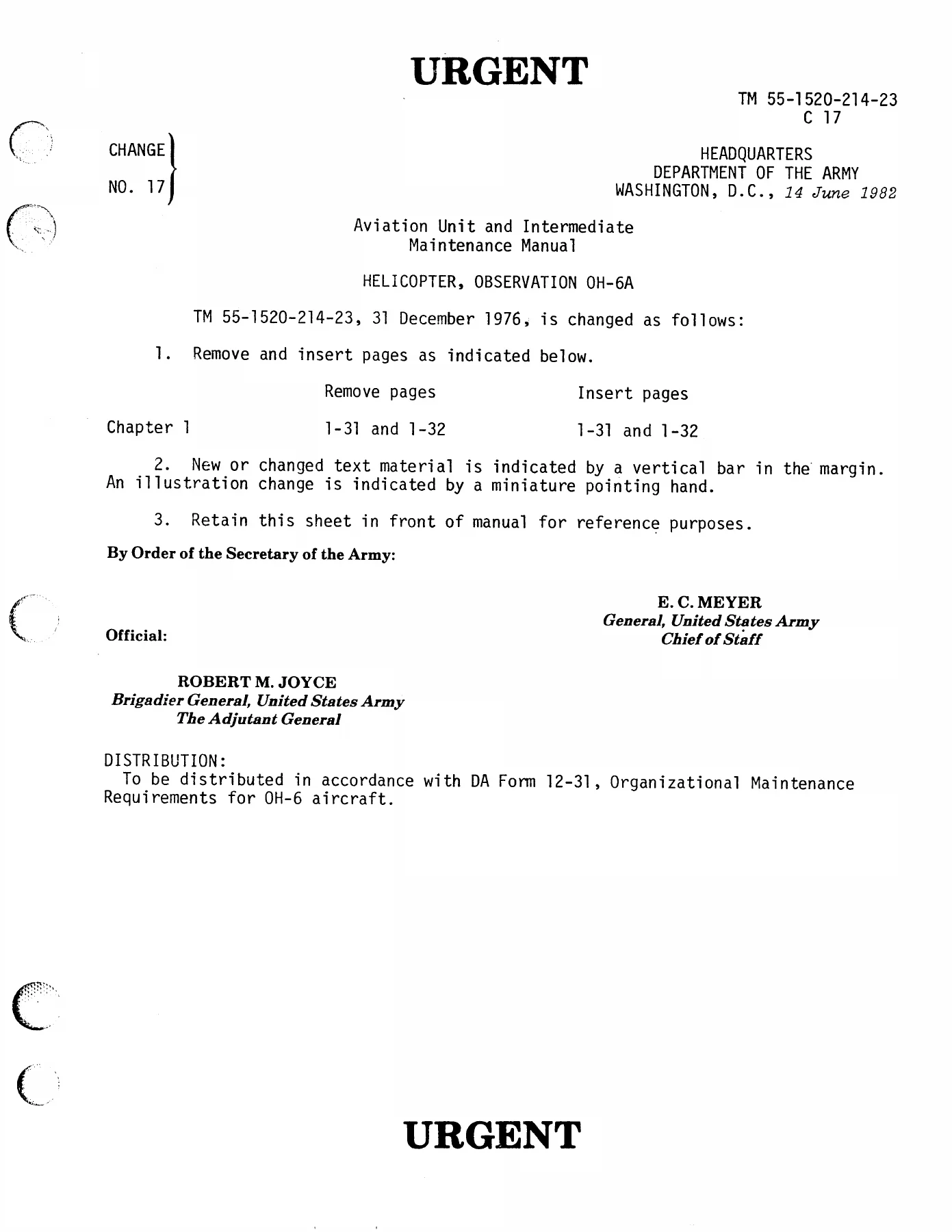
Hughes OH-6A Cayuse Helicopter Aviation Unit and Intermediate Maintenance Manual TM 55-1520-214-23 — PDF page 28 preview
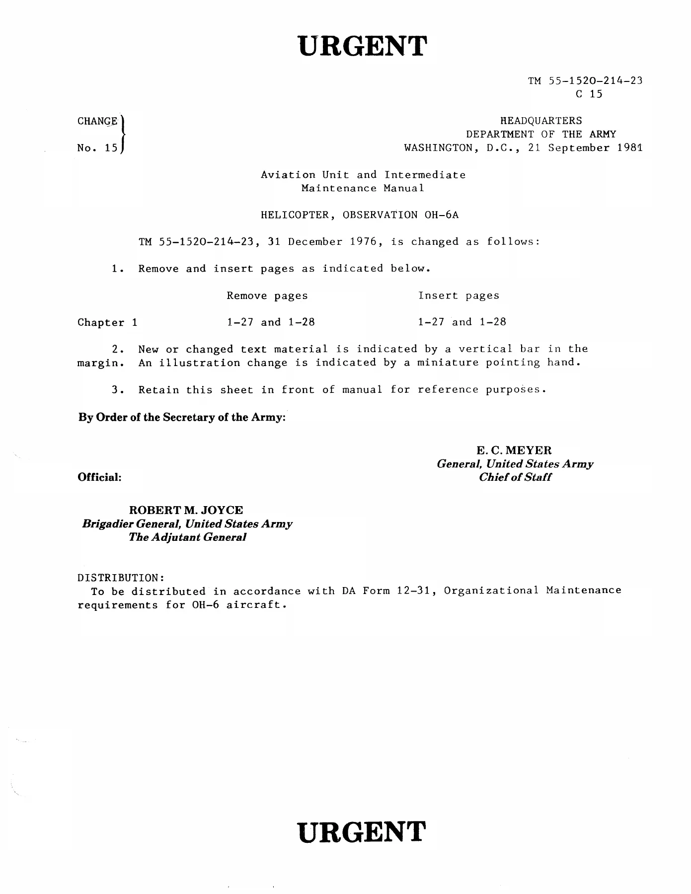
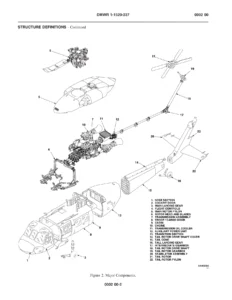
Hughes OH-6A Cayuse Helicopter Aviation Unit and Intermediate Maintenance Manual TM 55-1520-214-23 — PDF page 30 preview
Hughes OH-6A Cayuse Helicopter Aviation Unit and Intermediate Maintenance Manual TM 55-1520-214-23 — PDF page 58 preview

Together, these technical divisions provide an exhaustive resource enabling intermediate repair facilities and flight line maintainers to perform everything from routine 25-hour/30-day battery checks and 150-hour transmission fluid changes to complete teardown and replacement of dynamic flight assemblies.

Professional Capability and Instant Delivery

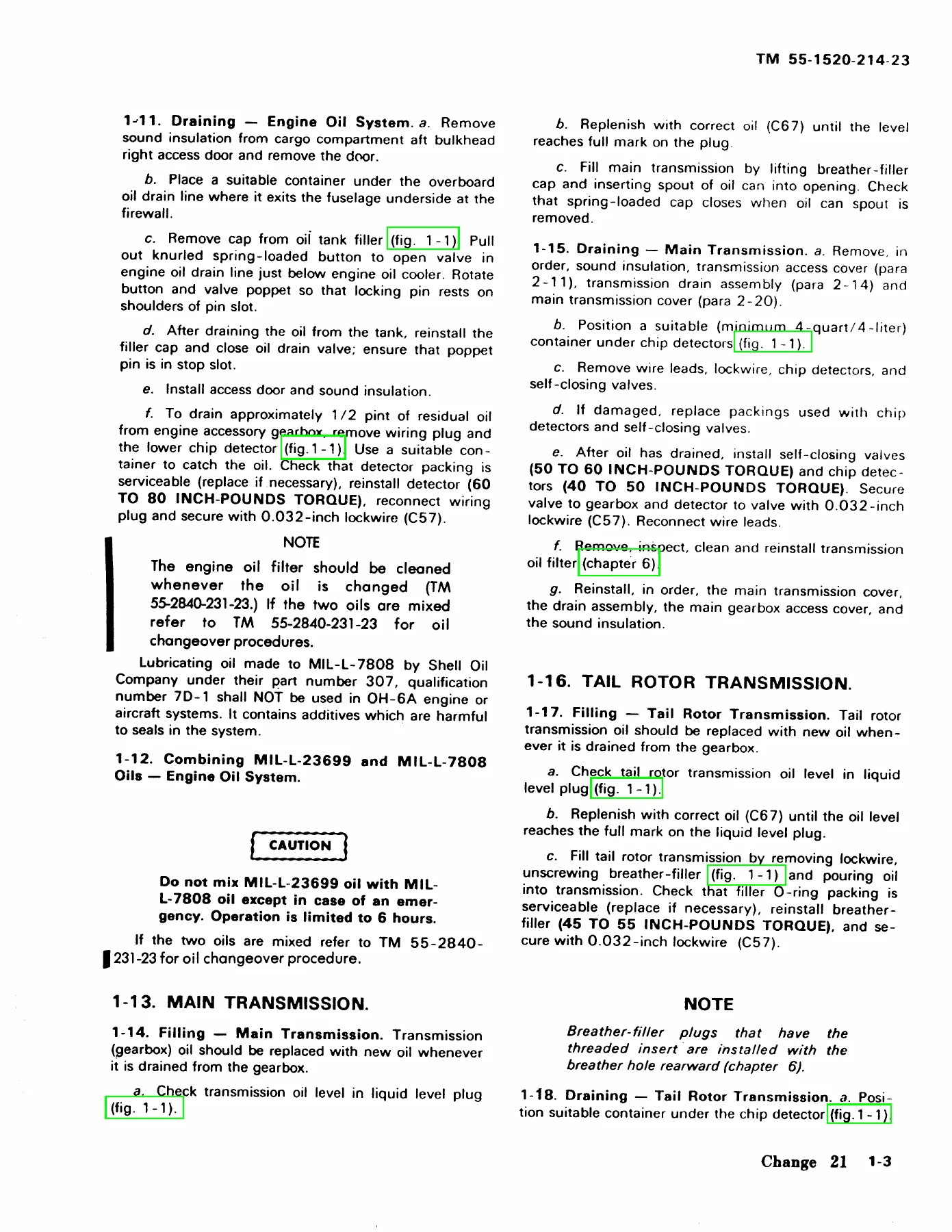
Working with authentic maintenance procedures ensures airworthiness, operational reliability, and maximum safety for both flight crew and ground personnel. The Hughes OH-6A Cayuse Helicopter Aviation Unit and Intermediate Maintenance Manual TM 55-1520-214-23 gives technicians the exact engineering tolerances, torque limits (such as chip detector tightening torques of 40 to 50 in-lb and self-closing valves at 50 to 60 in-lb), and structural guidelines needed to keep this historic observation helicopter flight-ready.

This manual is supplied as an instant PDF download immediately upon checkout, allowing rapid viewing on laptops, tablets, or shop desktop workstations without shipping wait times. The high-clarity digital pages are fully printable, letting you print specific wiring foldouts, inspection checksheets, or mechanical overhaul diagrams directly for use in the hangar or flight line.
Reviews

There are no reviews yet.

Be the first to review “Hughes OH-6A Cayuse Helicopter Aviation Unit and Intermediate Maintenance Manual TM 55-1520-214-23”

What Our Customers Say

★★★★★ Live reviews from customers
Loading customer reviews...
0
    0
    Your Cart
    Your cart is emptyReturn to Shop
    🛒
    Recently Purchased
    🕒 verified order