Skyjack SJ6826 RT & SJ6832 RT Rough Terrain Scissor Lift Service Manual (157951AF) – 2023 PDF
$34.95 Original price was: $34.95.$19.95Current price is: $19.95.
Complete 2023 Skyjack service manual for the SJ6826 RT and SJ6832 RT Compact Rough Terrain scissor lifts (document 157951AF) covering scheduled maintenance, function tests, hydraulic and electrical schematics, troubleshooting and full repair procedures.
Description
Skyjack SJ6826 RT & SJ6832 RT Rough Terrain Scissor Lift Service Manual – 157951AF
This is the full Skyjack service manual for the SJ6826 RT and SJ6832 RT Compact Rough Terrain Series scissor lifts, published under document number 157951AF with a 2023 date. It is the workshop-level document used to maintain, test, diagnose and repair these two machines, and it applies to units in the serial range 37 002 788 through 37 004 670 for both models.
File Details
- Manual type: Service & Maintenance Manual
- Brand: Skyjack
- Models covered: SJ6826 RT, SJ6832 RT (Compact Rough Terrain Series)
- Document number: 157951AF
- Publication year: 2023
- Language: English
- Page count: 156 pages
- File format: PDF
Chapters Covered
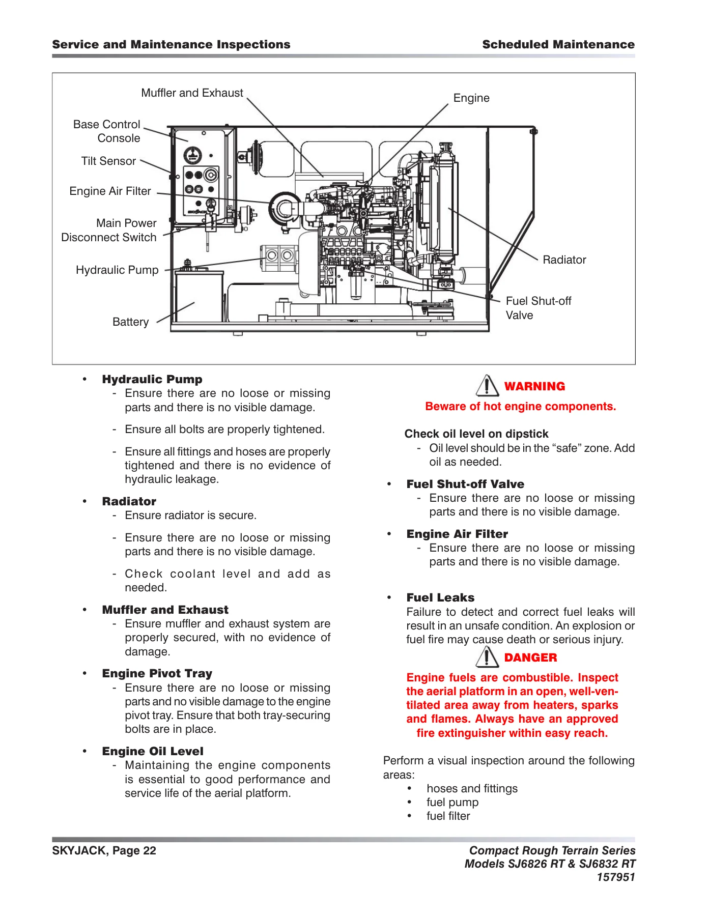
- Section 1 – Scheduled Maintenance
- Operator’s responsibility for maintenance
- Aerial platform definition, purpose and use of equipment
- Manuals, operator duties, service policy and warranty
- Electrocution hazard and minimum safe approach distance
- Safety precautions and jobsite inspection
- Maintenance and inspection schedule
- Owner’s annual inspection record
- Replacement parts and maintenance hints
- Hydraulic system and component maintenance and repair
- Railing maintenance and repair
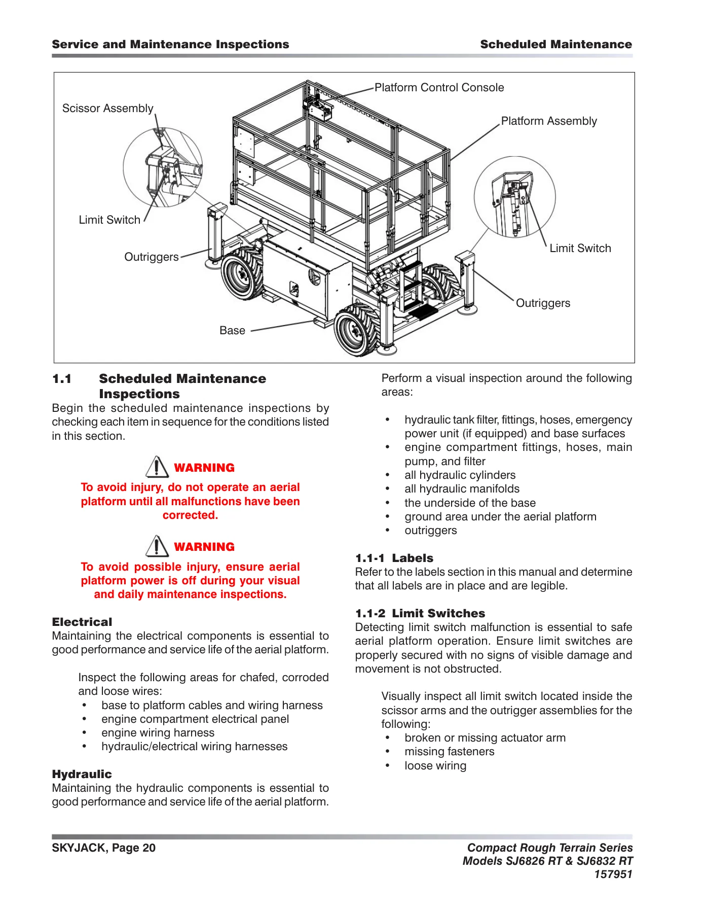
- 1.1 Scheduled maintenance inspections
- 1.2 Function tests
- Section 2 – Maintenance Tables and Diagrams
- Specifications and features
- Floor loading pressure (LCP and OUP)
- Maximum platform capacities
- Fluids table
- Torque specifications
- Torque specifications for fasteners (imperial and metric)
- Torque specifications for hydraulic couplings and hoses
- Section 3 – System Component Identification and Schematics
- Hydraulic symbol chart
- Electrical symbol chart
- Hydraulic schematic parts list
- Electrical parts list
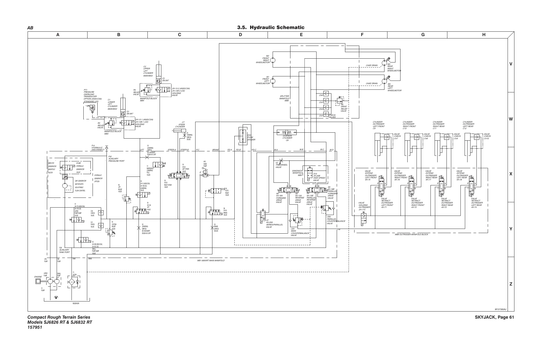
- Hydraulic schematic
- Hydraulic manifolds and ports identification
- Control box with rotary switches wiring diagram
- Control box with toggle switches wiring diagram
- Outrigger / hydraulic generator control console wiring diagram
- Scissor arm control cable wiring diagram
- Main manifold harness wiring diagram
- Kubota engine wiring diagrams (dual fuel and diesel)
- Outrigger harness wiring diagram
- Hydraulic generator electrical panel assembly
- Flashing light relay harness
- Electrical panel wiring diagram
- Electrical schematics by engine and control box configuration
- Section 4 – Troubleshooting
- Electrical troubleshooting (4.1 series: no power, engine crank and start faults, glow plugs, choke, throttle, drive and steer, brakes, lift and lower circuits, hydraulic generator, outriggers)
- Hydraulic troubleshooting (4.2 series: pump, steering, drive speeds, brakes, lift and lower circuits, outriggers)
- Outrigger control module flash code diagnostics
Complete PDF Bookmark TreeComplete Bookmarks
The complete bookmarks in the βSkyjack SJ6826 RT & SJ6832 RT Rough Terrain Scissor Lift Service Manual (157951AF) – 2023 PDFβ are as follows:
Table of Contentsp. 3+Section 1 – Scheduled Maintenancep. 5
+Operatorβs Responsilbility for Maintenancep. 7
Aerial Platform Definitionp. 7Purpose of Equipmentp. 7Use of Equipmentp. 7Manualsp. 7Operatorp. 7Service Policy and Warrantyp. 7Optional Accessoriesp. 7Scope of this Manualp. 8Operator Safety Remindersp. 8Electrocution Hazardp. 9Safety Precautionsp. 10Maintenance and Inspection Schedulep. 14Ownerβs Annual Inspection Recordp. 14Replacement Partsp. 14Maintenance and Service Safety Tipsp. 14Hydraulic System & Component Maintenance and Repairp. 15Maintenance Hintsp. 16Railing Maintenance and Repairp. 16+Service and Maintenancep. 17
About this Sectionp. 17Service Bulletinsp. 17Maintenance and Inspectionp. 17Maintenance Instructionsp. 17+Tablesp. 18
Table 1.1 Ownerβs Annual Inspection Recordp. 18Table 1.2 Maintenance and Inspection Checklistp. 19+Service and Maintenance Inspectionsp. 20
1.1 Scheduled Maintenance Inspectionsp. 201.2 Function Testsp. 31+Section 2 – Maintenance Tables and Diagramsp. 41
+Tablesp. 42
Table 2.1 Specifications and Featuresp. 42Table 2.2 Floor Loading Pressurep. 44Table 2.3 Maximum Platform Capacities (Evenly Distributed)p. 45Table 2.4 Fluids Tablep. 46Table 2.5 Torque Specificationsp. 47Table 2.6 Torque Specifications for Fasteners (Imperial)p. 48Table 2.7 Torque Specifications for Fasteners (Metric)p. 49Table 2.8 Torque Specifications for Hydraulic Couplings & Hosesp. 50+Section 3 – System Component Identification and Schematicsp. 51
+Chartsp. 52
3.1. Hydraulic Symbol Chartp. 523.2. Electrical Symbol Chartp. 533.3. Hydraulic Schematic Parts Listp. 54+Parts Listp. 54
3.4. Electrical Parts Listp. 56+Diagrams and Schematicsp. 61
3.5. Hydraulic Schematicp. 613.6. Hydraulic Manifolds And Ports Identificationp. 623.7. Control Box with Rotary Switches Wiring Diagramp. 643.8. Control Box with Toggle Switches Wiring Diagramp. 653.9. Outrigger/Hydraulic Generator Control Console Wiring Diagramp. 663.10. Scissor Arm Control Cable Wiring Diagramp. 673.11. Main Manifold Harness Wiring Diagramp. 683.12. Kubota Engine Wiring Diagram (Dual Fuel System)p. 693.13. Kubota Engine Wiring Diagram (Diesel Fuel System)p. 703.14. Outrigger Harness Wiring Diagramp. 713.15. Hydraulic Generator Electrical Panel Assemblyp. 723.16. Flashing Light Relay Harnessp. 733.17. Electrical Panel Wiring Diagramp. 743.18. Electrical Schematic (No Option with Kubota Dual Fuel Engine and Rotary Switch Control Box)p. 753.19. Electrical Schematic (All Option with Kubota Dual Fuel Engine and Rotary Switch Control Box)p. 763.20. Electrical Schematic (All Option with Kubota Diesel Engine and Rotary Switch Control Box)p. 773.21. Electrical Schematic (No Option with Kubota Dual Fuel Engine and Toggle Switch Control Box)p. 783.22. Electrical Schematic (All Option with Kubota Dual Fuel Engine and Toggle Switch Control Box)p. 793.23. Electrical Schematic (All Option with Kubota Diesel Engine and Toggle Switch Control Box)p. 80Introductionp. 83+Section 4 – Troubleshooting Informationp. 81
+Electrical Systemp. 84
4.1-1 All Controls Inoperativep. 844.1-2 No Power To Platformp. 844.1-3 All Functions Inoperative from The Platformp. 854.1-4 Engine Will Not Crank from Platform or Base Control Consolep. 854.1-5 Engine Cranks But Will Not Start – Kubota Dieselp. 864.1-6 Engine Cranks But Will Not Start – Kubota Dual Fuelp. 864.1-7 Glow Plugs Inoperative from Engine Controls or Platform (Diesel Models)p. 874.1-8 Choke Inoperative from Engine Controls or Platform (Kubota Dual Fuel)p. 874.1-9 High Throttle Inoperativep. 884.1-10 High Throttle On Demand Inoperative (Kubota Dual Fuel)p. 894.1-11 Drive and Steer Inoperative (Machines without outriggers option)p. 894.1-12 Drive and Steer Inoperative (Machines with outriggers option)p. 904.1-13 Brakes Will Not Releasep. 914.1-14 Steer Right Inoperativep. 914.1-15 Steer Left Inoperativep. 914.1-16 Reverse Drive Inoperativep. 924.1-17 Forward Drive Inoperativep. 924.1-18 First Drive Speed and Steering Inoperativep. 934.1-19 Second Drive Speed Inoperativep. 934.1-20 Third Drive Speed Inoperativep. 944.1-22 High Drive Speed Inoperativep. 954.1-21 Up Circuit Inoperative from Platformp. 954.1-22 Up Circuit Inoperative from Base Control Consolep. 964.1-23 Up Circuit Inoperative from Platform or Base Control Console (without Outriggers)p. 964.1-24 Platform will Not Lift from Platform or Base Control Console with Outriggers Retracted (Lift Operates Correctly with Outriggers Extended)p. 964.1-25 Platform will Not Lift from Platform or Base Control Console with Outriggers Extendedp. 974.1-26 Platform will Not Lift from Platform or Base Control Console with Outriggers Extended or Retractedp. 984.1-27 Down Circuit Inoperative from Platformp. 984.1-28 Down Circuit Inoperative from Basep. 994.1-29 Hydraulic Generator Inoperativep. 994.1-30 Hydraulic Generator will not Shut Off from Generator Switchp. 1004.1-31 All Outriggers Inoperative (Auto-Level and Manual)p. 1004.1-32 All Outriggers Inoperative (Auto-Level and Manual from Platform Controls)p. 1014.1-33 All Outriggers Inoperative (Base Controls only)p. 1014.1-34 All Outriggers Inoperative (Auto Level only)p. 1014.1-35 All Outriggers Inoperative (Auto Level only)p. 1024.1-36 Left Front Outrigger Inoperative Manuallyp. 1044.1-37 Right Front Outrigger Inoperative Manuallyp. 1044.1-38 Right Rear Outriggers Inoperative Manuallyp. 1044.1-39 Left Rear Outriggers Inoperative Manuallyp. 1044.1-40 Individual Outrigger Functions Inoperative (Auto-Level)p. 1054.1-41 Auto-Level Inoperativep. 1054.1-42 Auto All Up Inoperative (Retract)p. 105+Hydraulic Systemp. 106
4.2-1 All Functions Inoperativep. 1064.2-2 Steering Inoperativep. 1064.2-3 Lift, Steer and First Drive Speed Inoperativep. 1064.2-4 Second Drive Speed Inoperativep. 1064.2-5 Drive Inoperativep. 1064.2-6 Drive Sluggishp. 1074.2-7 Reverse Drive Inoperativep. 1074.2-8 Forward Drive Inoperativep. 1074.2-9 Drive Inoperative When in Low Drivep. 1074.2-10 Drive Inoperative When in High Drivep. 1074.2-11 Brakes Will Not Releasep. 1074.2-12 Up Circuit Inoperativep. 1074.2-13 Down Circuit Inoperativep. 1084.2-14 Hydraulic Generator Inoperativep. 1084.2-15 All Outriggers Inoperativep. 1084.2-16 Left Front Outriggers Inoperativep. 1084.2-17 Right Front Outriggers Inoperativep. 1084.2-18 Right Rear Outriggers Inoperativep. 1084.2-19 Left Rear Outriggers Inoperativep. 1094.2-20 Outriggers Drift Inp. 109+Section 5 – Proceduresp. 111
+Generalp. 113
5.1-1 Safety and workmanshipp. 113+Platformp. 114
5.2-1 Adjust the gate spring hingep. 1145.2-2 Platform mounting hardwarep. 114+Scissorsp. 115
5.3-1 Replace and adjust high speed cutout limit switch (LS5)p. 1155.3-2 Test the high speed cutout limit switchp. 116+Enginep. 117
5.4-1 Kubota dual fuel DF972 resistance checksp. 1175.4-2 Kubota dual fuel DF972 engine throttle settingp. 1185.4-3 Kubota diesel D902 engine throttle settingp. 1195.4-4 Replace the fuel filter element – Kubota D902p. 121+Basep. 126
5.5-1 Inspect and torque the wheel bolts and nutsp. 1265.5-2 Install and torque the wheelsp. 1265.5-3 Reconnect the platform control box for use from the groundp. 1275.5-4 Grease pointsp. 1285.5-5 Electronic tilt switch setup procedurep. 129+Hydraulicsp. 132
5.6-1 Tightening and torque recommendations for hydraulic couplings and hosesp. 1325.6-2 Do a check of the holding valvep. 1335.6-3 Set the system pressurep. 1345.6-4 Set the lift pressurep. 135+Outriggersp. 136
5.7-1 Outrigger mechanical limit switch wiring diagramp. 1365.7-2 Replace and adjust the Outrigger upper limit switches (LS61, LS62, LS63, LS64)p. 1375.7-3 Replace and adjust the Outrigger lower limit switches (LS65, LS66, LS67, LS68)p. 138+EZcal Diagnostic Toolp. 139
5.8-1 Hand held EZcal calibration and diagnostic tool key functionsp. 1395.8-2 Flash the controllerp. 1405.8-3 Outrigger codesp. 141+OCM1 Control Modulep. 142
5.9-1 Auto-leveling outrigger PC board layoutp. 1425.9-2 Outrigger control module (OCM1) instructionsp. 1435.9-3 Auto-leveling outrigger settings and error codesp. 1455.9-4 Auto-leveling outrigger error code breakdownp. 146+GP-106 Control Modulep. 147
5.10-1 Set up the GP-106 outrigger controllerp. 1475.10-2 GP-106 Outrigger controller pin reference tablep. 148+GP-108 Control Modulep. 149
5.11-1 Set up the GP-108 outrigger controllerp. 1495.11-2 GP-108 outrigger controller pin reference tablep. 1515.11-3 LED Error codesp. 153 - Section 5 – Procedures
- Safety and workmanship
- Platform gate hinge and platform mounting hardware
- High speed cutout limit switch (LS5) replacement, adjustment and test
- Kubota dual fuel DF972 resistance checks and throttle setting
- Kubota diesel D902 throttle setting
- Fuel filter element replacement and bleeding the fuel system
- Fan belt replacement and adjustment
- Air cleaner element, oil filter cartridge and engine oil service
- Radiator coolant check, drain and refill
- Wheel bolt and nut torque, wheel installation
- Reconnecting the platform control box for ground-level service
- Grease points
- Electronic tilt switch setup and reprogramming
- Hydraulic coupling and hose torque practice
- Holding valve check
- System pressure and lift pressure setup
- Outrigger limit switch replacement and adjustment
- EZcal diagnostic tool, outrigger codes and controller flashing
- Outrigger control module (OCM1) menus and error codes
- GP-106 and GP-108 outrigger controller setup and pin reference tables
Across its five sections the manual moves from routine upkeep to component-level repair. The scheduled maintenance portion defines what has to be checked daily, quarterly, annually and bi-annually, then walks through function tests that confirm the platform raises, lowers, steers, drives, brakes and levels as designed. From there the tables give the numbers a technician needs to work to – capacities, fluid types, fastener and hydraulic coupling torque values, floor loading pressure and machine weights. The schematics section supplies the hydraulic and electrical maps for the machine, including manifold port identification and the various engine and control-box configurations. The troubleshooting section is organised as numbered fault charts, each listing probable causes alongside the remedy, so a technician can work from symptom to failed wire, relay, coil, switch or valve. Finally, the procedures section gives step-by-step instructions with torque values and adjustment figures for the work that keeps these lifts in service.
What This Manual Covers in Depth
Because it is written for both models, the Skyjack SJ6826 RT and SJ6832 RT service manual separates the shared content from the model-specific detail. Where a specification or adjustment differs between the SJ6826 RT and the SJ6832 RT, the manual states the figure for each – for example the lowering orifice diameter and the working and elevated platform heights. Coverage extends to the Kubota diesel and Kubota dual fuel engine variants, to machines with and without the outrigger option, and to both rotary switch and toggle switch platform control boxes, with dedicated electrical schematics for each combination.
Safety material is included up front rather than buried: the minimum safe approach distance table for energized power lines, electrocution hazard warnings, jobsite inspection guidance and the operating precautions that apply before any maintenance or repair is attempted.
Who This Manual Suits
Owners and operators of an SJ6826 RT or SJ6832 RT who are responsible for the inspection schedule will find the checklists and the owner’s annual inspection record useful for keeping a documented maintenance history. Service technicians and workshops working on these scissor lifts get the fault charts, wiring and hydraulic diagrams, pressure setting procedures and torque tables needed to diagnose and repair rather than replace by guesswork. Fleet maintenance departments can standardise inspection and repair practice across both models using one document.
Why It Matters
These are mobile elevating work platforms that carry people at height, so incorrect adjustment or an unchecked fault is not a minor inconvenience. Working from the manufacturer’s stated pressures, torque values, limit switch settings and diagnostic sequences is what keeps the machine operating within the limits it was designed for. The troubleshooting charts in particular shorten diagnosis by pointing to the specific wire numbers, relays, diodes and coils involved in each fault rather than leaving a technician to trace the whole circuit.
IMAGES PREVIEW
Instant PDF Delivery
The manual is supplied as a PDF that is available to download immediately after purchase – no shipping, no waiting for a parcel, no binder to lose. Keep it on a laptop or tablet in the workshop, print the pages you need for a particular job, and print extra copies of the maintenance and inspection checklist for each service interval. Whether you are servicing an SJ6826 RT or an SJ6832 RT, this 2023 Skyjack service manual gives you the complete reference in one file.
What Our Customers Say
π Related Products
Discover more professional manuals for your equipment

LiuGong CLG922E Excavator Service Manual 201503001 - Cummins QSB6.7 Workshop Repair Guide

Doosan DX700LC Excavator Shop Manual 950106-00013E 2010 Repair Guide

JLG E450AJ PVC 2101 Service & Maintenance Manual 2021 - PDF Download


Reviews
There are no reviews yet.