
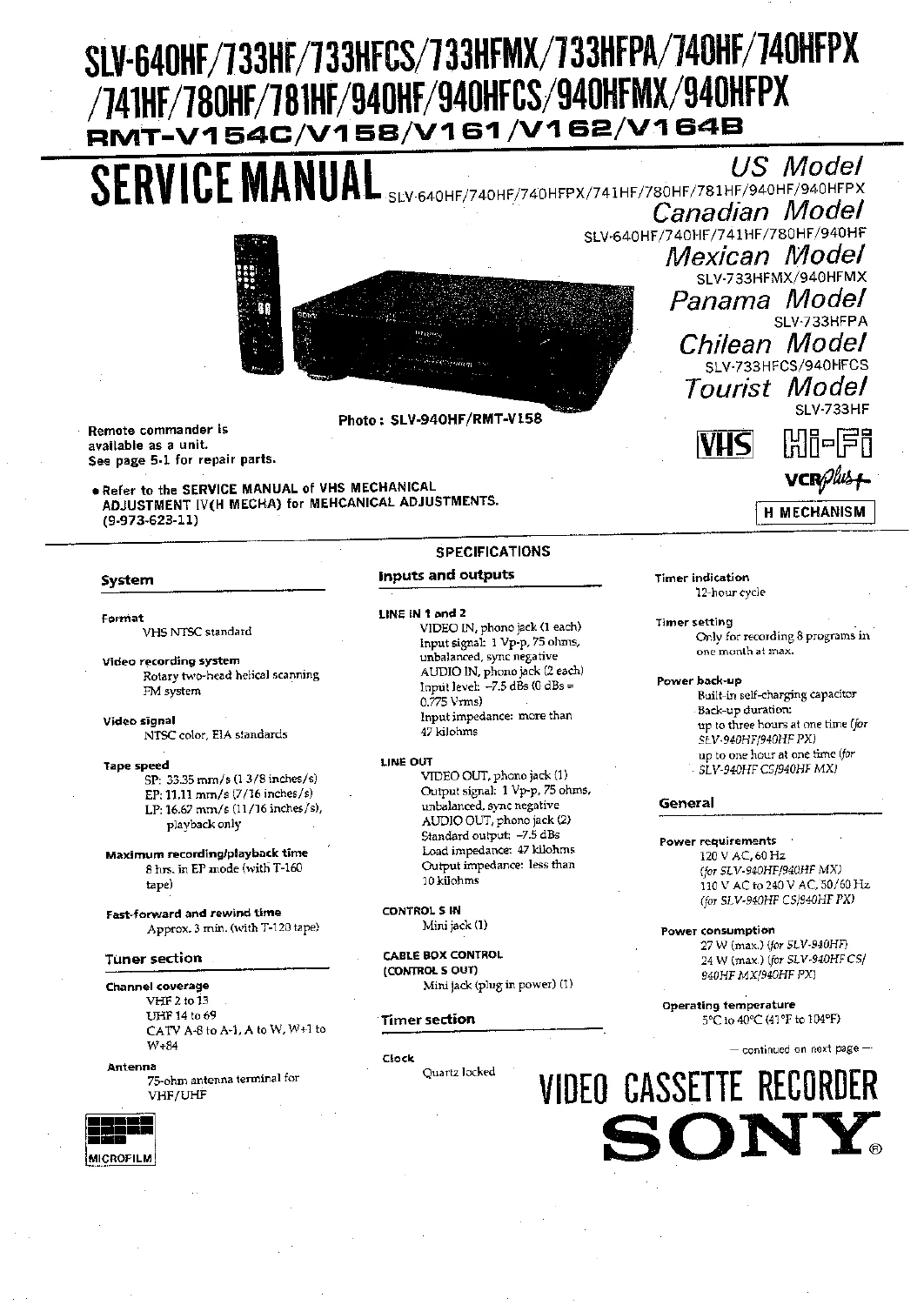
Sony SLV Series VHS VCR Service Manual – SLV-640HF, 733HF, 740HF, 780HF, 940HF H Mechanism Repair Guide
Original price was: $34.95.$19.95Current price is: $19.95.
Complete Sony SLV Series H Mechanism VHS VCR service manual covering SLV-640HF through SLV-940HFPX models – disassembly, block diagrams, schematics, electrical and mechanical adjustments, exploded views and full parts lists.
Description
Sony SLV Series VHS VCR Service Manual – H Mechanism Models
This Sony SLV Series VHS VCR Service Manual covers the H Mechanism video cassette recorders built for the US, Canadian, Mexican, Panamanian, Chilean and Tourist markets, spanning the SLV-640HF, SLV-733HF, SLV-733HFCS, SLV-733HFMX, SLV-733HFPX, SLV-740HF, SLV-740HFPX, SLV-741HF, SLV-780HF, SLV-781HF, SLV-940HF, SLV-940HFCS, SLV-940HFMX and SLV-940HFPX. It is written for the person who actually opens the deck: board-level schematics, signal-flow block diagrams, alignment procedures and exploded parts views all sit in one document rather than being scattered across supplements.
File Details
- Manual type: Service Manual (with VHS Mechanical Adjustment Manual IV supplements)
- Brand: Sony
- Series: SLV Series VHS Video Cassette Recorder, H Mechanism
- Language: English (safety notices also given in French)
- Page count: Approximately 200 pages
- File format: PDF
- Document content: Service notes, disassembly, block diagrams, printed wiring boards, schematics, repair parts list, IC pin functions, adjustments, mechanical adjustment supplements
Chapters Covered
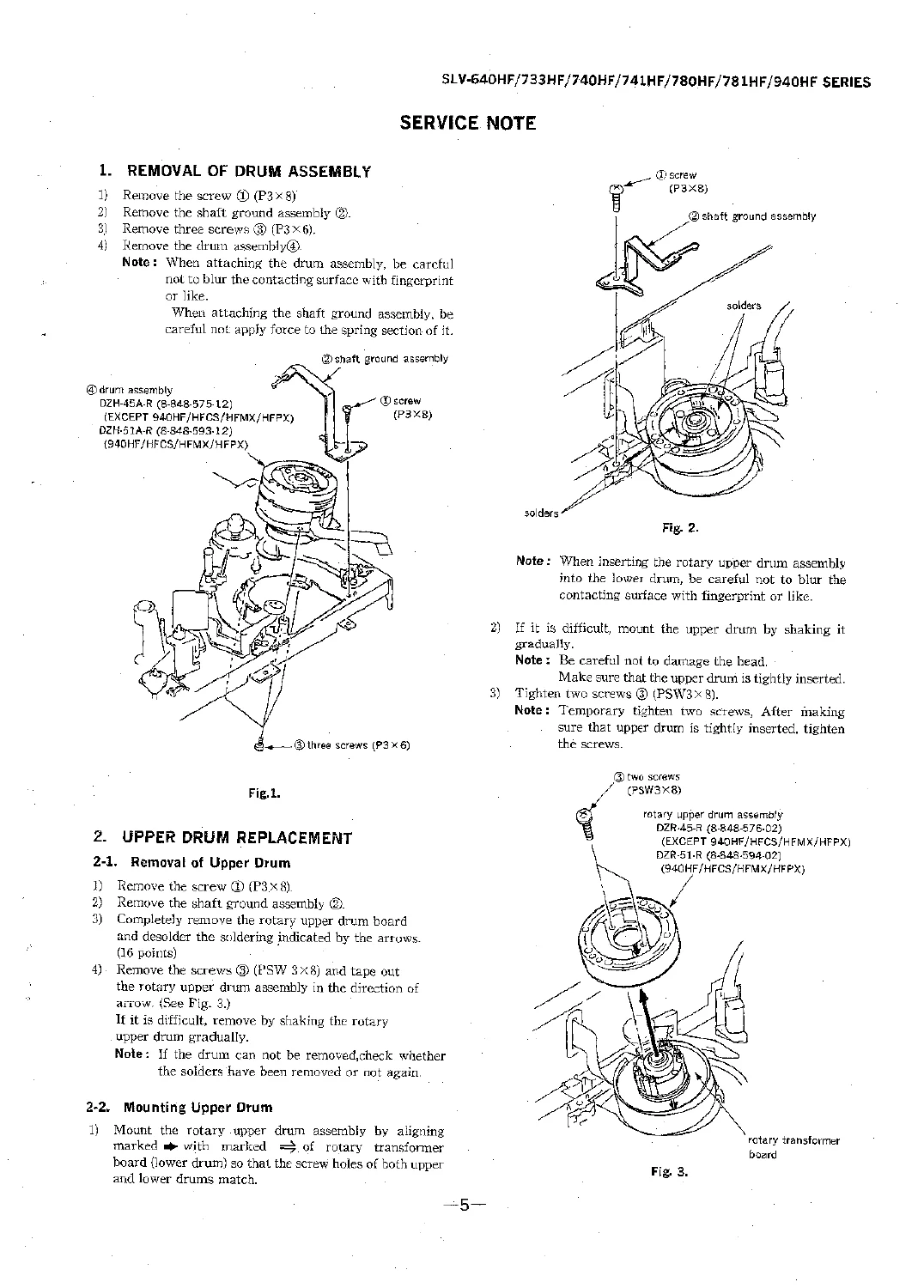
- Service Note – Removal of drum assembly, upper drum replacement, periodic check and replacement, cleaning of the rotating head disk assembly, tape movement system and drive system
- 1. General – Unpacking, setting up the remote commander, hookups, selecting a language, setting the clock, presetting channels, cable box control, VCR Plus+, advanced options, playing a tape, recording TV programs, timer recording, checking and changing timer settings, playing at various speeds, adjusting the picture, index search, editing with another VCR, insert editing, synchronized editing, general setup information, index to parts and controls
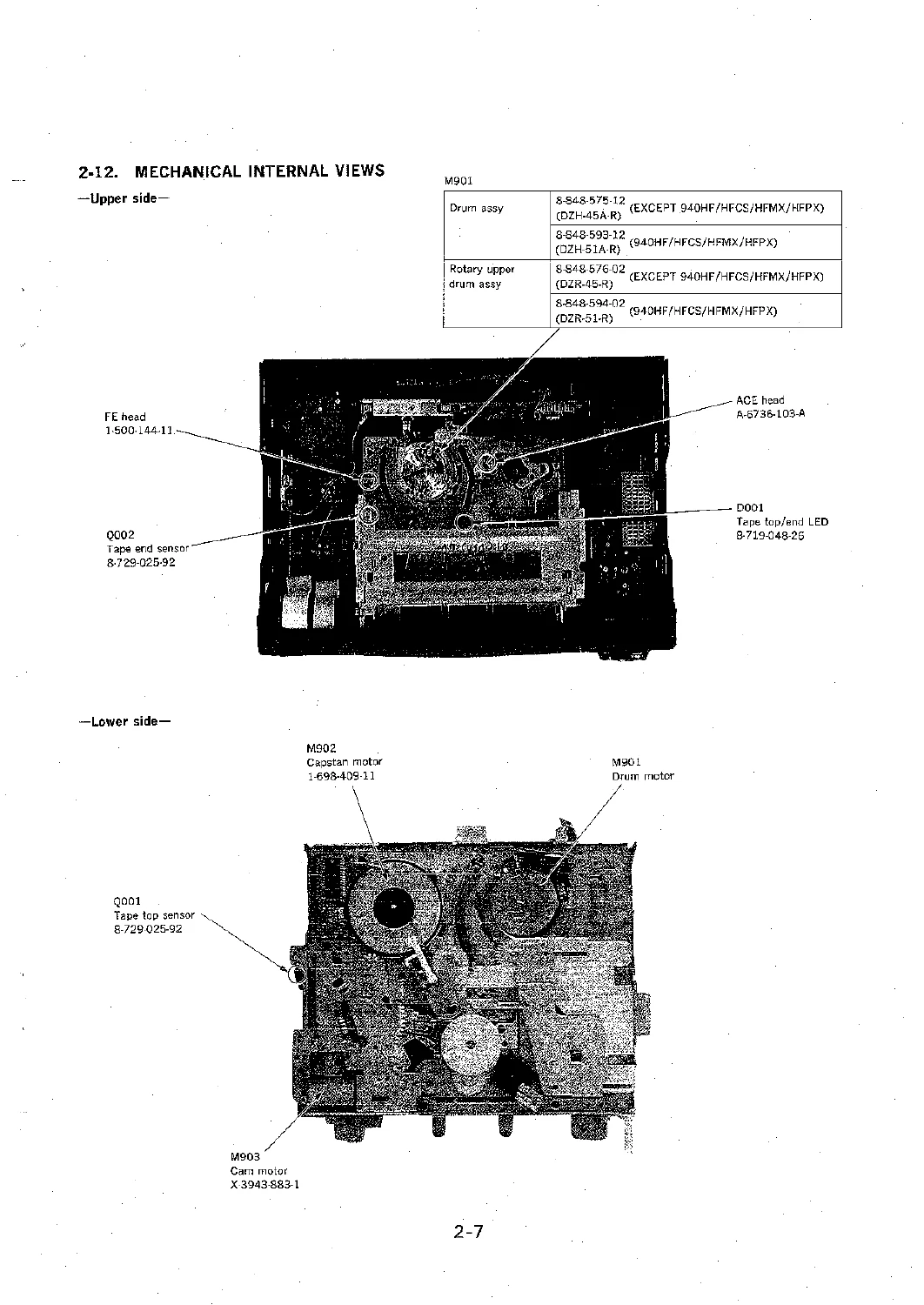
- 2. Disassembly – Upper case, front panel assembly, control switch block, MF-253/274 board, HI-5/19 board, bottom plate, PS-327/349 board, ED-40/43 and HF-34 boards, RV-36/45 board, MA-214 board, MD block assembly, mechanical internal views, circuit boards location
- 3. Block Diagrams – Overall, video, servo and system control, timer/tuner/mode control, audio, tuner, power
- 4. Printed Wiring Boards and Schematic Diagrams – Frame schematic, RV-36/45 board, MA-214 (servo/syscom) and DG-97/95 board, MA-214 (input/output, tuner), ED-40/43 board, HF-34 and MF-253/274 boards, PS-327/349 board
- 5. Repair Parts List – Exploded views for case assembly, front panel assembly, chassis assembly and mechanical deck assemblies, electrical parts lists per board, hardware list
- 6. Interface and IC Pin Function – System control to video, servo peripheral, mechanism, system control peripheral, audio, and HF modulator/input section interfaces; CXPS7240 497A and MF89065FFG-36 port function descriptions
- 7. Adjustments – Mechanical adjustments, electrical adjustments, equipment required, equipment connection, input signal check, alignment tape, specified input-output levels, power supply check, output voltage check, servo system adjustment, clock adjustment, video system adjustment, X’tal OSC check, SYNC AGC check, white clip/dark clip check, Y FM carrier frequency check, playback Y level check, audio system adjustment, VCO frequency adjustment, deviation check, band pass filter adjustment, AF switching position adjustment, ACE head adjustment, recording bias adjustment, E-E output level check, overall output level and distortion factor check, overall noise level check, adjustment parts location diagram
The manual is organised the way a repair actually happens. You start with the disassembly sequence to get the cabinet and boards out, then use the board location diagram and block diagrams to trace where a signal should be going, then drop into the printed wiring board and schematic pages for component-level work. The parts list gives you the reference numbers and Sony part numbers for what you are about to order, and the adjustment chapter tells you what to measure, on which pin, with which instrument, and what the reading is supposed to be.
Alignment data in this volume is unusually specific. Playback Y level, SYNC AGC, white clip and dark clip percentages, Y FM carrier frequency, the 5.5H RF switching position, Hi-Fi VCO frequencies at 1.3 MHz and 1.7 MHz, deviation, band pass filter balance, recording bias at 40 Hz versus 7 kHz, and clock accuracy are all called out with tolerance bands rather than vague guidance. The servo and system control section covers the CXPS7240 497A microprocessor port by port, and the timer/tuner section does the same for the MF89065FFG-36, which is what you need when a fault sits between the mechanism and the logic rather than inside either one.
Model differences matter on this series, and the manual handles them properly. Several boards exist in two versions depending on whether the machine is a 733HF/HFCS, 740HFPX or 940HFCS/HFPX variant – MF-253 versus MF-274, HI-5 versus HI-19, PS-327 versus PS-349, RV-36 versus RV-45, ED-40 versus ED-43, DC-57 versus DC-65. Each disassembly step and each schematic page states which board applies to which model, so you are not left guessing whether the board in front of you matches the diagram you are reading.
What This Manual Lets You Do
With this Sony SLV Series service manual on hand you can strip a machine down to the chassis, replace an upper drum, set the tape path, run the full electrical alignment, and reassemble it correctly. You can trace a video or Hi-Fi audio fault from the head amplifier through to the output jacks using the block diagrams and schematics, then confirm the repair against the published tolerance values instead of guessing. You can look up the exact part number for a mechanical deck component, a sensor, a motor or a board before ordering, and you can check the critical safety-related components that are marked in the parts list and schematics so replacements meet the original specification.
Getting the alignment right is the difference between a VCR that plays and one that eats tapes. The tracking, X-value, ACE head height and tilt, guide roller height, tension regulator and torque figures in this manual are what keep the tape running where it should, and the adjustment sequence is laid out in the order it must be performed. The same applies on the electrical side: the recording bias and VCO adjustments directly determine whether Hi-Fi audio comes back clean or distorted.
IMAGES PREVIEW
The manual is delivered as an instant PDF download – no shipping, no waiting for a disc. It opens on a workshop PC, laptop, tablet or phone, and any page or diagram you need at the bench can be printed and marked up without worrying about damaging an original. Whether you are servicing a single SLV-940HF for a customer, restoring a SLV-733HF for yourself, or working through a shelf of these H Mechanism decks, the same file covers all of them.


Reviews
There are no reviews yet.