
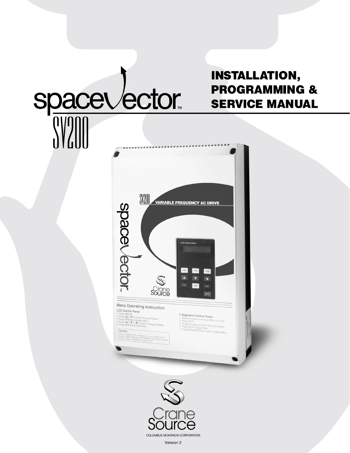
SpaceVector SV200 Series Drive Installation, Programming & Service Manual
Original price was: $34.95.$21.95Current price is: $21.95.
Complete installation, programming and service manual for the SpaceVector SV200 Series PWM drive used in overhead material handling. Covers 230 V and 460 V classes from 3 HP to 30 HP, with keypad programming, full function code library, wiring diagrams and fault code troubleshooting.
Description
SpaceVector SV200 Series Drive – Installation, Programming & Service Manual
The SpaceVector SV200 Series is a PWM drive engineered specifically for the overhead material handling industry, and this is the complete installation, programming and service reference for it. The document covers the full SV200 lineup in both the 230 V and 460 V classes, from the 3 HP frame up through the 30 HP frame, and it is written for the technician who mounts the drive, wires the power and control circuits, programs the function codes, and keeps the equipment running in crane and hoist service.
Anyone searching for a SpaceVector SV200 Series drive installation, programming and service manual will find the practical answers here: what wire gauge belongs on which terminal, how the 120 VAC interface card connects to the pushbutton pendant, how to walk the keypad through the function code tree, which fault code means the DC bus is over voltage, and exactly what the factory macro settings change when a hoist or traverse application is selected.
File Details
- Manual type: Installation, Programming & Service Manual
- Brand: Columbus McKinnon Corporation / SpaceVector
- Series: SV200
- Drive classes covered: 230 V and 460 V, 3 HP through 30 HP
- Part numbers covered: 446485-10 through 446485-17 (230 V class) and 446485-20 through 446485-27 (460 V class)
- Language: English
- Pages: 112
- Format: PDF
Chapters Covered
- Chapter 1 – Installation: inspection of the drive, mounting clearances and enclosure dimensions, wiring the power leads, dynamic braking resistor wiring, 120 VAC interface card connection, pushbutton pendant control wiring, control terminal descriptions, precautionary checks before operation
- Chapter 2 – Start Up Programming: keypad layout, keypad operation, jump code navigation, viewing functions within a group level, changing control from pendant to keypad, initial setup programming, macro quick set application selection, speed selection programming, drive operation checks
- Chapter 3 – Programming: passwords and group access levels, entering and changing a password, customizing function data, establishing motor parameters including rated slip, rated current and no-load current
- Chapter 4 – Troubleshooting: monitoring frequency, current and speed, monitoring fault trips, fault code descriptions with causes and solutions, problem flowcharts for motor-does-not-run, speed deviation and motor overheating, testing power components, pushbutton pendant test, multi-function output test
- Chapter 5 – Function Code Information: User level functions, Service level functions and Advanced level functions covering drive mode, frequency reference source, energy save, analog frequency control, maximum and minimum operating frequency, frequency to bypass, DC injection braking, motor data, drive and motor protections, stall prevention, instantaneous power failure and speed search, restart after reset, carrier frequency, closed loop speed control, rotation direction prevention, jog frequency, frequency detection, speed display scaling, option card settings and reverse plugging
- Chapter 6 – Maintenance: routine inspection, visual inspection, high-voltage service precautions
- Appendix: sample traverse wiring diagram, sample hoist wiring diagram with analog control, and timing diagrams for 2 speed, 2 step infinitely variable, 3 speed, 3 step infinitely variable and 5 speed control
What the SV200 Manual Gives You
This is not a generic VFD pamphlet. The SV200 was programmed from the ground up for crane and hoist duty, and the manual reflects that. The macro quick set programming chapter alone saves hours on a new installation: you select Hoist with LB, Hoist without LB or Traverse, and the drive rewrites a whole block of related parameters – accel and decel patterns, torque boost values, multi-function input assignments, stop mode, stall prevention and overcurrent limit operation time – in one step. The manual documents every one of those cascading changes in reference tables so you can see exactly what moved and why.
Beyond initial setup, the function code chapter is the real meat. It splits the drive into User, Service and Advanced access levels and lists the code number, display name, description, range and factory default for every parameter. That includes analog input scaling, filter gain, bias and polarity; frequency jump bands for resonance avoidance; DC injection braking timing; electronic thermal protection levels; stall prevention modes for acceleration, steady speed and deceleration; and speed search behaviour after an instantaneous power failure.
Wiring, Dynamic Braking and Pendant Control
Installation coverage is unusually thorough for a drive of this class. You get the arrangement of the power terminal strip, the recommended wire gauges by drive class, fuse and moulded-case circuit breaker selection tables, and the grounding practice that avoids ground loop problems when several drives share a panel. Dynamic braking resistors are treated as a required component for hoisting and traverse duty, and the manual explains the consequences of a bad connection – rising DC bus voltage and an over voltage fault – plus where to place the resistor so its heat does not cook the drive.
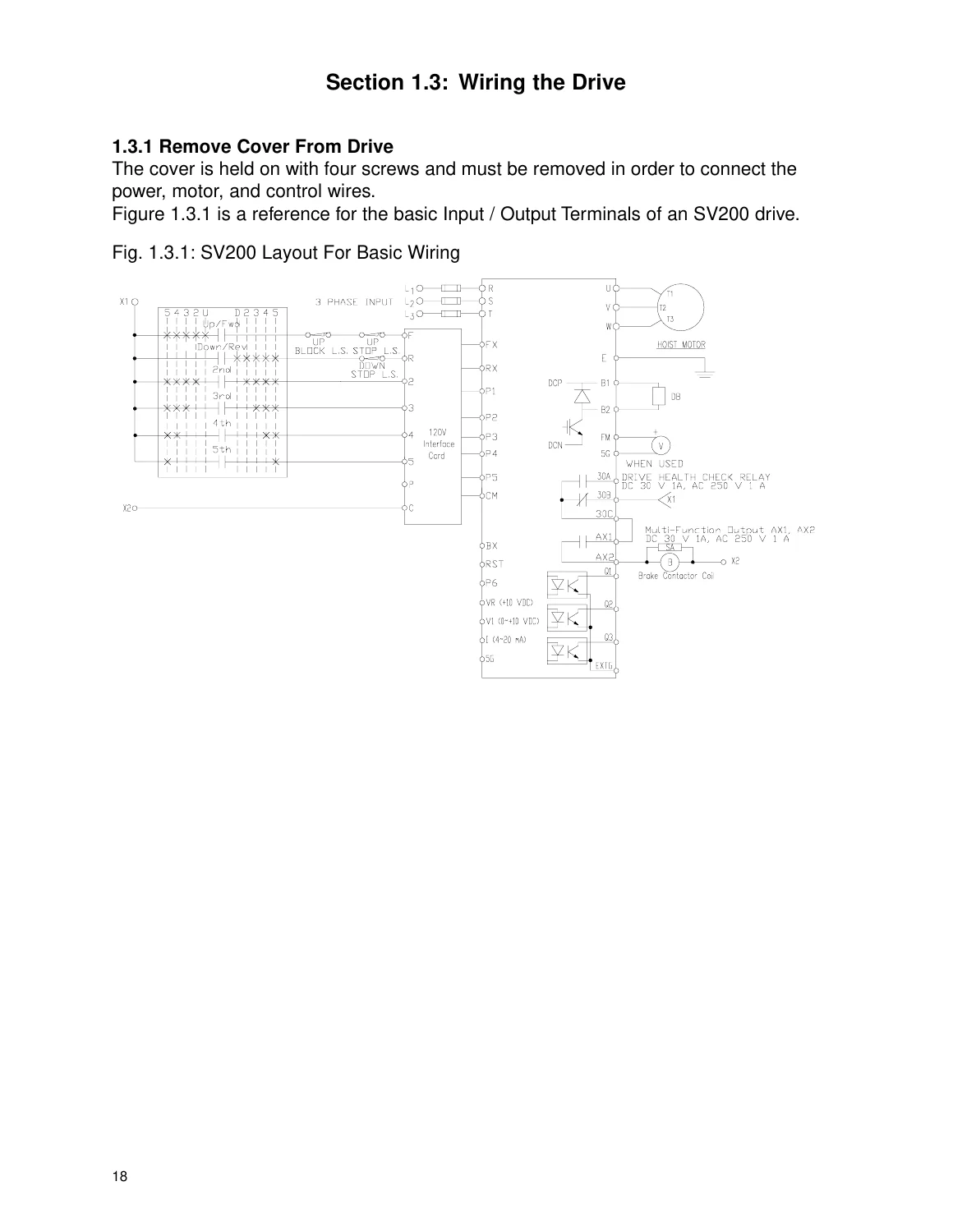
The 120 VAC interface card section shows how the card plugs into the control terminal strip and how the pushbutton pendant wires up for raise/forward traverse, lower/reverse traverse and up to five speed steps. A separate test procedure lets you read the live status of every pendant input from the keypad, so you can prove the interface card and the control board independently.
Diagnostics and Fault Codes
Troubleshooting is built around the drive’s own fault history. Fault code USE 14 shows the current trip with the frequency and current recorded at the moment it happened, and the two previous trips are held in Last Fault 1 and Last Fault 2. Each fault – OC Trip, GF Trip, OV Trip, OL Trip, Phase Loss, Fuse Open, Over Heat, ETH, EXT Trip, LV Trip and BX – is listed with the likely causes and the corrective steps, from extending acceleration time to reducing torque boost to checking motor windings for a ground fault. Flowcharts walk through the motor-does-not-run, wrong-speed and overheating scenarios in a logical sequence.
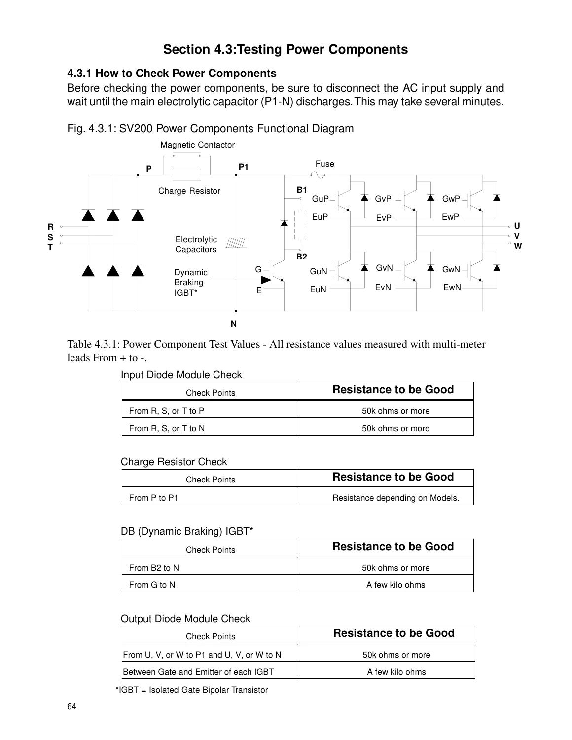
For component-level work, the manual includes a functional diagram of the drive’s power section and resistance test values for the input rectifier, the charge resistor, the dynamic braking IGBT and the output diode module, measured with a standard multimeter.
Why This Manual Matters
An SV200 that trips on over voltage every time the hoist lowers, or that will not hold speed under load, usually has a parameter problem rather than a hardware failure. Guessing at function codes on a live crane is a fast way to create a bigger fault. With the correct function code references, the brake release frequency and dwell timing tables, and the macro setting charts in hand, a technician can put the drive back into a known state instead of chasing symptoms.
The same manual supports commissioning too: motor parameter calculation from nameplate data, slip frequency formulas, minimum drive phase loss detection current, electronic thermal protection level calculation and the drive model selection cross-reference that links each part number to its factory default rated current and no-load current.
IMAGES PREVIEW
Instant PDF Delivery
This SV200 Series drive installation, programming and service manual arrives as an instant PDF download after payment – no shipping, no waiting on a paper copy. Open it on a laptop, tablet or phone at the panel, search it for a specific function code, or print the wiring and fault code pages you need for the job. Everything from the 230 V and 460 V specification tables to the keypad flowcharts is in one file you keep.
Reviews
There are no reviews yet.