


Still Wagner FM Type 447 Workshop Manual – FM12 FM14 FM17 FM20 Electric Forklift Repair PDF
Original price was: $29.95.$18.95Current price is: $18.95.
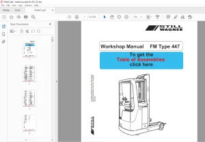
Complete Still Wagner FM Type 447 workshop manual for FM12, FM14, FM17 and FM20 electric forklift trucks. Covers travel drive, steering, brakes, electrical system, hydraulics and service software across 199 pages.
Description
Still Wagner FM Type 447 Workshop Manual
This is the full workshop manual for the Still Wagner FM Type 447 series of electric industrial trucks. It is the reference document that the Still Wagner service organisation uses to specify, maintain and repair the FM-group vehicles, and it covers the FM12 (1.2 t), FM14 (1.4 t), FM17 (1.7 t) and FM20 (2.0 t) capacity trucks in a single volume. Every system on the truck is broken down into its assemblies with the technical data, adjustment values, removal and installation sequences, and testing routines needed to carry the work out correctly.
Because the manual is written for the FM group as a whole, the same procedures and specifications apply across all four capacity ratings unless a specific variant is called out. That makes this a practical single-source document whether you are working on one truck or a mixed fleet.
File Details
- Manual type: Workshop Manual
- Brand: Still Wagner
- Model series: FM Type 447
- Models covered: FM12, FM14, FM17, FM20
- Language: English
- Page count: 199 pages
- File format: PDF
- Document number: 8054226
- Issue: 05/01
- Publisher: STILL WAGNER GmbH & Co. KG, Trainingcenter, Reutlingen-Mittelstadt
Chapters Covered
- Chapter A – Travel drive: drive motor general and technical data, motor connection specifications, carbon brush monitoring, temperature monitoring, speed sensor terminals and testing, replacing the carbon brushes, changing the drive wheel, removing and installing the drive motor, mast hitch and half mast hitch, removing/installing the gear, commissioning the gear, changing the gear oil, drive motor maintenance
- Chapter B – Steering system: block diagram, steering unit general and technical data, function, connections, error codes, removal, installation, dismantling the drive unit, setpoint potentiometer (general, connections/signals, testing, removal, installation), adjusting the turning force of the steering wheel, actual value potentiometer (general, connections/signals, testing, removal, installation), adjustment of the entire steering system
- Chapter C – Brake system: general, electro-magnetic brake (function, removal, changing the brake disk, adjusting the brake clearance, adjusting the braking moment, releasing the brake mechanically, checking the brake coil), hydraulic/mechanical brake (function, plan of the hydraulic braking system, removal, adjusting the brake clearance, adjusting the brake pedal, bleeding/filling the brake system, main brake cylinder, special base valve), generator drive motor brake, measuring the brake deceleration
- Chapter M – Electrical system: guide to components (basic equipment and optional extras), block diagram, travel and pump controller (FPS) general, guide to components, main current connections, control current connections, guide to wiring, logic board and main current circuits, DC/DC converter, control of the drive motor, functional principle of the main current circuits for travel, generator braking and hydraulics, safety circuit (general, roll-away monitor, error code specification)
- Chapter N – Hydraulic system: block diagram, functions (lifting/lowering main lift, reach, tilting/transverse shift/additional hydraulics), chassis valve block, reach carriage valve block, additional hydraulics valve block, pre-pressure valves for reach, line break protection, load holding valve, pump unit (general, technical data, removal, pump motor, carbon brush monitoring, temperature monitoring, removing the motor, replacing the carbon brushes, hydraulic pump), tank display and tank, runback filter
- Chapter R – Lubrication plan: lubrication plan, lubricants, taking out of service and disposal
- Chapter V – Service software: Servicemaster menu guide, commissioning the steering, commissioning the hydraulics, loading parameters, diagnosis (error memory, list of errors, setpoint signals, input switching signals, LAS software update), WinPulsE menu guide, changing parameters, changing configuration, reading in the accelerator pedal, test function, error codes
In total this is a complete service reference for the FM Type 447 truck. A technician gets the drive and steering systems documented down to potentiometer resistance values and error codes, the brake system with its three-part layout fully explained, the electrical architecture with the FPS and LAS modules described and their error codes itemised, and the hydraulic system with the valve blocks, pump unit and line break protection. The service software chapter means the same book also supports steering teaching-in, hydraulic commissioning and parameter changes through Servicemaster and WinPulsE.
What This Manual Enables You To Do
With the Still Wagner FM Type 447 workshop manual on hand, the jobs that would otherwise require guesswork become procedure-driven. You can remove and refit the drive motor using the correct rope and crowbar method, change the drive wheel to the specified 140 Nm tightening torque, adjust the electro-magnetic brake clearance to 0.2-0.35 mm, and set the braking moment against the factory dimension. The steering chapter takes you through setpoint and actual value potentiometer replacement, resistance checks around 1325 ohms at centre, and the full teaching-in routine, including the A/D converter calibration and flutter adjustment.
On the electrical side the manual is equally specific. The main current circuits for travel, generator braking and hydraulics are described at MOSFET level, the roll-away monitor is explained, and the FPS error codes FE01 through FE43 are listed with their causes. The hydraulic chapter gives the valve block variants, the diaphragm sizes that must not be altered, the pressure relief valve setting procedure based on measured operating pressure plus ten percent, and the maximum lowering speed check against the 60 cm/sec limit.
Getting the procedures and specifications right matters on equipment like this. A drive wheel nut torqued by feel, a brake clearance set too wide, a lowering speed left above the permissible value or a steering system not re-commissioned after a potentiometer change will all come back as faults, premature wear or, in the case of the brake system, a safety problem. The manual removes that risk by giving the actual values and the actual sequence.
The lubrication plan adds the routine side of ownership, covering the toothed gears, bolster bearings, chains, idling wheel bearings, mast profiles and sliding surfaces with their intervals and the correct lubricant types.
IMAGES PREVIEW
Instant PDF Delivery
The manual is delivered as an instant PDF download after payment. There is no shipping and no waiting, and the file can be opened on a workshop laptop, tablet or phone and printed if you prefer a paper copy at the machine. Whether you are servicing an FM12, FM14, FM17 or FM20, the same document covers the job end to end.
Reviews
There are no reviews yet.