
Takeuchi TB290-2 Hydraulic Excavator Workshop Repair Manual – Book No. CM4E001
Original price was: $39.95.$23.95Current price is: $23.95.
Complete 620-page Takeuchi TB290-2 hydraulic excavator workshop manual (Book No. CM4E001) covering serial numbers 190500001 and up – service data, hydraulic and electrical systems, disassembly and assembly, troubleshooting, error codes and the full air conditioner section.
Description
Takeuchi TB290-2 Hydraulic Excavator Workshop Repair Manual – Book No. CM4E001
This is the full workshop manual for the Takeuchi TB290-2 hydraulic excavator, issued under Book No. CM4E001 and written for the machines from serial number 190500001 onward. It is a 620-page service document that walks a technician through the TB290-2 from top to bottom: the Yanmar 4TNV98CT-WTB diesel engine, the load-sensing hydraulic system, the undercarriage and travel motors, slew equipment, the working attachment, the operating devices and the cab air conditioning circuit.
Unlike an operator booklet, this Takeuchi TB290-2 workshop repair manual is built around procedures. It gives the standard and allowable values you measure against, the order in which components come apart, the torques that put them back together, and the diagnostic flow that isolates a fault before anything is removed from the machine.
File Details
- Manual type: Workshop Manual
- Brand: Takeuchi
- Model: TB290-2 hydraulic excavator
- Book No.: CM4E001
- Applicable serial number: 190500001~
- Language: English
- Page count: 620
- File format: PDF
Chapters Covered
- 1. Safety – safety alert symbol, safety labels, safety precautions, cautions when working, handling of seals, pressure adjustment for hydraulic devices
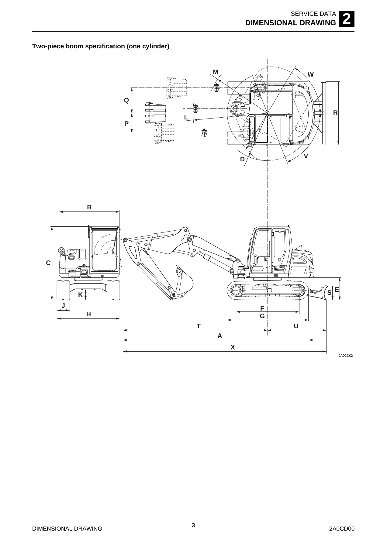
- 2. Service Data – completed machine dimensions, main unit dimensions, specification table, performance, engine, hydraulic equipment, control equipment, switch layout, lighting and warning equipment, slewing equipment, lower machinery, backhoe attachment, working ranges, hydraulic cylinder data, digging force, blade data, table of masses, fuel and lubricant table, volume table, performance evaluation standard, table of hydraulic pump assignment, tightening torque
- 3. Function – hydraulic pump, gear pump, control valve, sub control valve for 2nd service and slew, pilot valves (control lever, swing, blade, travel), proportional control solenoid valve, emergency shut-off valve, solenoid valve, selector valve, cylinders, travel motor, slew motor, swivel joint
- 4. Disassembly and Assembly – service standards, engine, hydraulic pump, fuel tank, battery, travel system, slew equipment, upper frame, operating device, attachments, hydraulic tank, gear pump, control valve, pilot valve, proportional control solenoid valve, emergency shut-off valve, solenoid valve, selector valve, cylinders, travel motor, slew motor, swivel joint
- 5. Troubleshooting – general, travel, shoe tension, slew, boom, arm, bucket, swing, blade, service, hydraulic pump, gear pump, control valve, pilot valve, solenoid valve, cylinders, travel motor, slew motor
- 6. Other – maintenance software manual, air conditioner, table of vehicle error codes, engine error code list
Read end to end, the manual is organised as a single service reference rather than a collection of notes. The Service Data chapter fixes the baseline – dimensions, masses, capacities, relief pressures, cylinder speeds and the allowable wear limits used during evaluation. The Function chapter explains how each hydraulic and electrical assembly actually works, which is what makes the later troubleshooting charts usable. The Disassembly and Assembly chapter carries the hands-on content for every major assembly, and the Troubleshooting chapter turns symptoms into a step-by-step test sequence that checks pilot pressure, main pressure and component leakage in a logical order.
What the TB290-2 Workshop Manual Covers in Detail
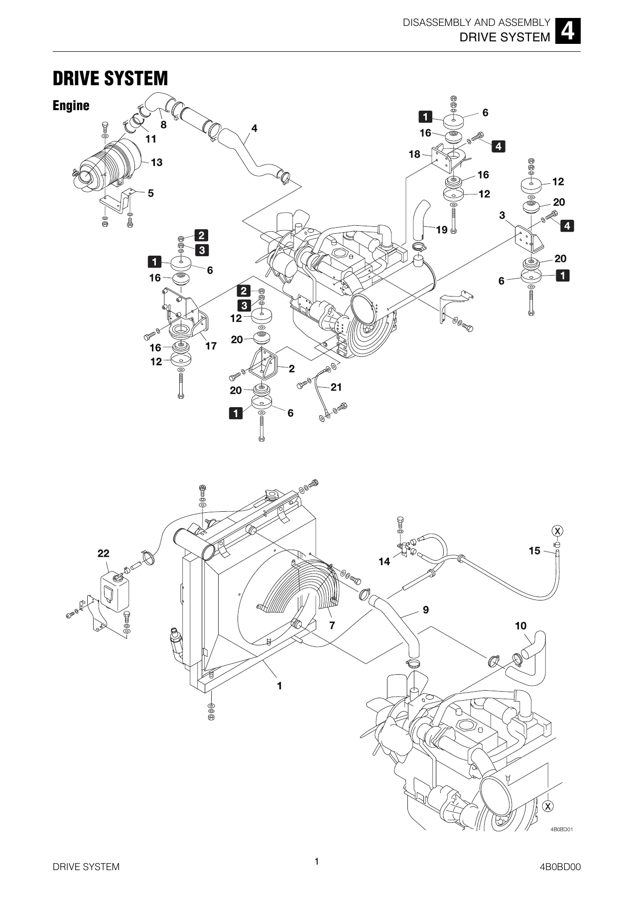
The engine content is built around the Yanmar 4TNV98CT-WTB, the four-cylinder water-cooled direct-injection diesel used in this machine. Removal and installation of the engine and radiator are described, including the clearance to be set between the cooling fan and the shroud, along with the fuel tank, sedimenter and fuel pump layout.
On the hydraulic side the Takeuchi TB290-2 service manual goes deep. The variable-displacement piston pump and the double gear pump are covered in both function and overhaul form, including the horsepower control regulator, the load sensing control regulator, the power shift piston and the feedback lever. The main control valve, the sub control valve for 2nd service and slew, the pilot valves, the proportional control solenoid valves, the emergency shut-off valves and the selector valve all receive their own sections with construction diagrams, disassembly sequences and inspection criteria.
Undercarriage and travel content covers crawler removal and installation for rubber, steel and segmented rubber crawlers, the reducing valve adjustment when switching crawler types, carrier and track rollers, idler and track adjuster, sprocket and the travel motor with its brake valve, relief valves, 2nd-speed switching mechanism, parking brake and two-stage planetary reduction gears. Slew equipment covers the slew motor, relief and make-up valves, timer valve, parking brake and reduction gears, plus the slew bearing and swivel joint procedures.
Diagnostics, Error Codes and Electrical Reference
The troubleshooting chapter is where this manual saves the most time in the field. It starts from the symptom – engine will not start, engine speed cannot be increased, all attachments and travel motors inoperable, travel motors inoperable, machine veers to one side, shoe not installed tautly, machine will not slew, slew slow and weak, slew stop flow excessive, boom will not rise or drop, boom drops temporarily, arm will not push or pull, large arm natural drop, bucket will not dig, swing inoperative, blade inoperative, 1st and 2nd service inoperative, quick-hitch will not lock or unlock – and drives each one down to a measurable cause with the correct pressure gauge connection point shown.
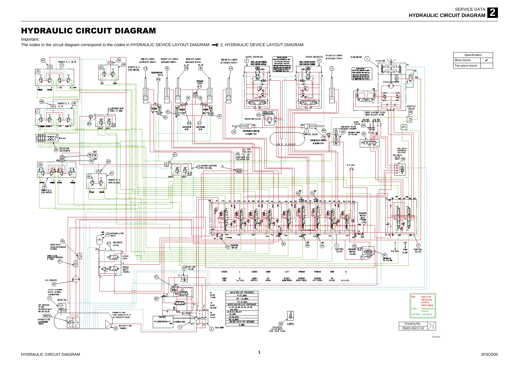
Supporting that are the hydraulic circuit diagrams, the hydraulic device layout diagram, the electrical circuit diagrams and the wire colour and wire type tables. The vehicle error code table and the engine error code list give the fault code, the detection port, the evaluation condition, the limit behaviour, buzzer behaviour and return conditions, so a code can be traced straight back to the circuit that produced it.
Air Conditioning and Maintenance Software
The air conditioner section covers the swashplate compressor, magnetic clutch, condenser, receiver dryer, expansion valve, pressure switches, heater core and blower. It includes the inspection and maintenance table, the refrigerant volume check table, compressor removal, condenser and receiver dryer service, evacuation, air-tightness checks, refrigerant charging, and a gauge manifold troubleshooting guide that interprets normal and abnormal high-side and low-side readings.
The maintenance software manual covers the PLUS+1 Service Tool connection method and the available screens – machine status, inputs, outputs, CAN, feedback, error codes, vehicle status, engine status, DPF record, AUX1 and AUX2 settings, grip pattern, lift alarm, hourmeter and engine auto stop.
Why Working From the Correct Procedures Matters
On a compact excavator the cost of guessing is high. A relief pressure set by feel rather than to the specified value changes cycle times and can load the engine or damage the pump. A crawler tensioned without following the grease discharge procedure is a safety risk. A cylinder reassembled with the piston nut at the wrong torque or without the set screw swaged can fail under load. A slew motor reassembled without matching the relief valve or the swash plate thickness can leak or lose braking performance.
This Takeuchi TB290-2 hydraulic excavator workshop repair manual removes that guesswork. It provides the tightening torques for hydraulic hose ends, pipe joints, O-ring seal joints and JIS strength category 10.9 bolts; the standard and allowable values for pin and bushing clearance; the wear limits for pump parts, cylinder rods and bushings; the correct sequence for bleeding air from hydraulic circuits and cylinders; and the correct method for releasing residual pressure before a hose is disconnected.
IMAGES PREVIEW
Instant PDF Delivery
The manual is delivered as an immediate PDF download once payment is complete – no shipping, no waiting, no physical binder to lose. It opens on a laptop, desktop, tablet or phone and can be printed in full or page by page for the workshop bench. Whether you are servicing the TB290-2 in a dealer workshop, running a fleet, or maintaining a single machine on site, this workshop manual gives you the manufacturer’s own procedures, values and diagnostic logic for the whole excavator in one document.


Reviews
There are no reviews yet.