
Takeuchi TL130 Crawler Loader Workshop Manual CT8E002 – PDF Download
Original price was: $63.95.$39.95Current price is: $39.95.
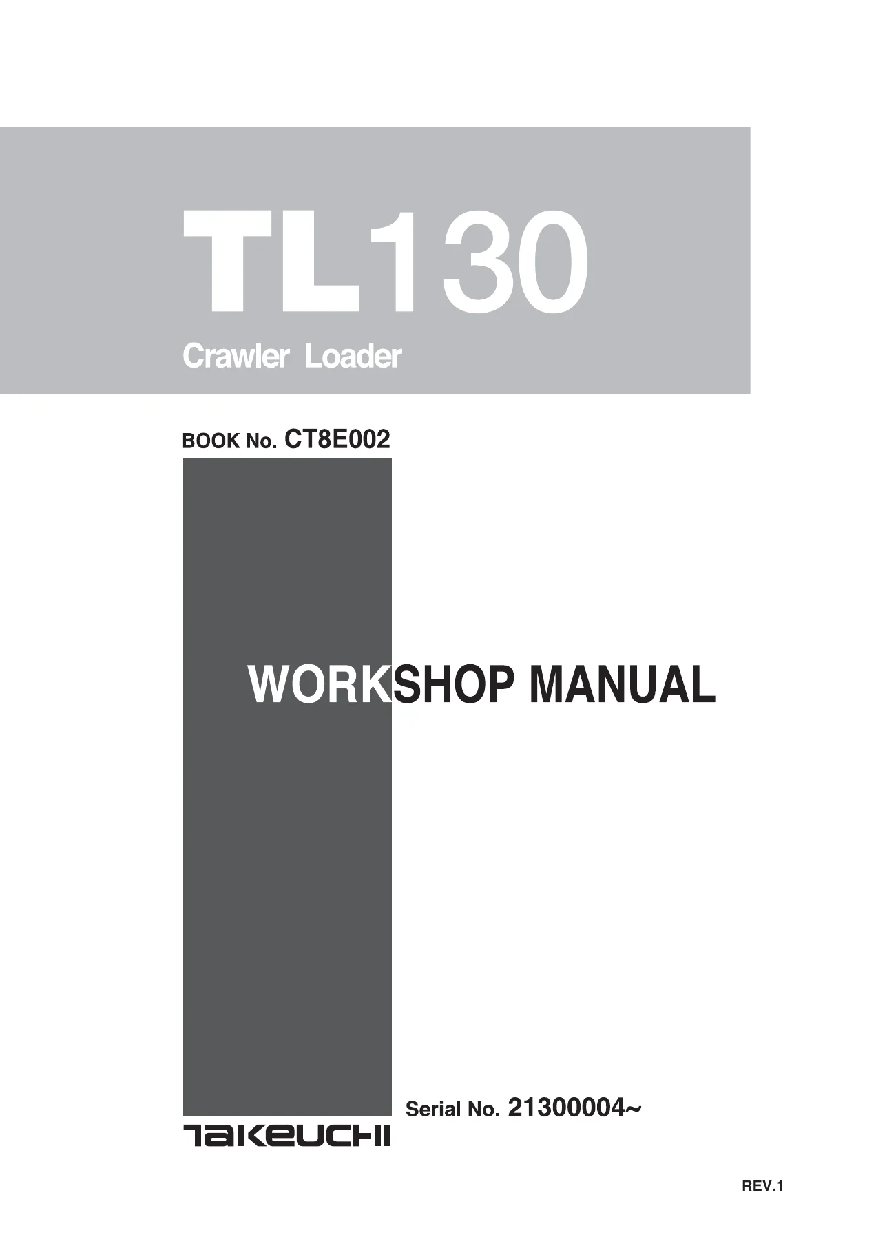
Complete 712-page Takeuchi TL130 Crawler Loader Workshop Manual (Book No. CT8E002) for serial number 21300004 and up. Full service, repair, hydraulic teardown, troubleshooting and Yanmar engine coverage in a single instant-download PDF.
Description
Takeuchi TL130 Crawler Loader Workshop Manual — Book No. CT8E002
This is the complete Takeuchi TL130 Crawler Loader Workshop Manual, published under Book No. CT8E002 and written for machine serial number 21300004 and up. Across 712 pages it delivers the full service, repair and overhaul reference for the TL130 — general safety and torque standards, complete machine specifications, system configuration, hydraulic unit teardown, structured troubleshooting, and the Yanmar engine service section. If you are pulling a travel motor, rebuilding an arm or bucket cylinder, chasing a slow lift arm, resetting main relief pressure, or diagnosing a crawler that veers to one side, the procedures, tolerances and reference values you need are all here.
File Details
- Manual type: Workshop Manual
- Brand: Takeuchi
- Model: TL130 Crawler Loader
- Document number: Book No. CT8E002
- Serial number coverage: 21300004~
- Language: English
- Page count: 712
- File format: PDF
Chapters Covered
- I. GENERAL
- II. SPECIFICATIONS
- III. MACHINE CONFIGURATION
- IV. HYDRAULIC UNITS
- V. TROUBLESHOOTING
- VI. ENGINE
I. GENERAL
The opening chapter sets the ground rules for working on a TL130. It covers the safety alert symbol and signal-word system (DANGER, WARNING, CAUTION, IMPORTANT), personal protective equipment, fire extinguisher and first-aid location, the DO NOT OPERATE tag, correct tool use, anti-explosive lighting, work-area preparation, machine blocking, hot and pressurized component handling, accumulator handling, grease-under-pressure warnings on the track adjuster, battery hazards, waste disposal, and welding repair guidance. The back half of the chapter gives you the full disassembly and assembly cautions, handling of seals, and — critically — the tightening torque tables: hydraulic hoses (union nut and taper thread), bite-type pipe fittings for steel pipe, joints for piping (steel and cast steel), O-ring seal type joints, UNF thread joints, and bolts and nuts for ISO strength category 10.9 in both coarse and fine pitch. General, special and thread-locking points are separated so you know where molybdenum disulfide grease or Three Bond #1324 applies.
II. SPECIFICATIONS
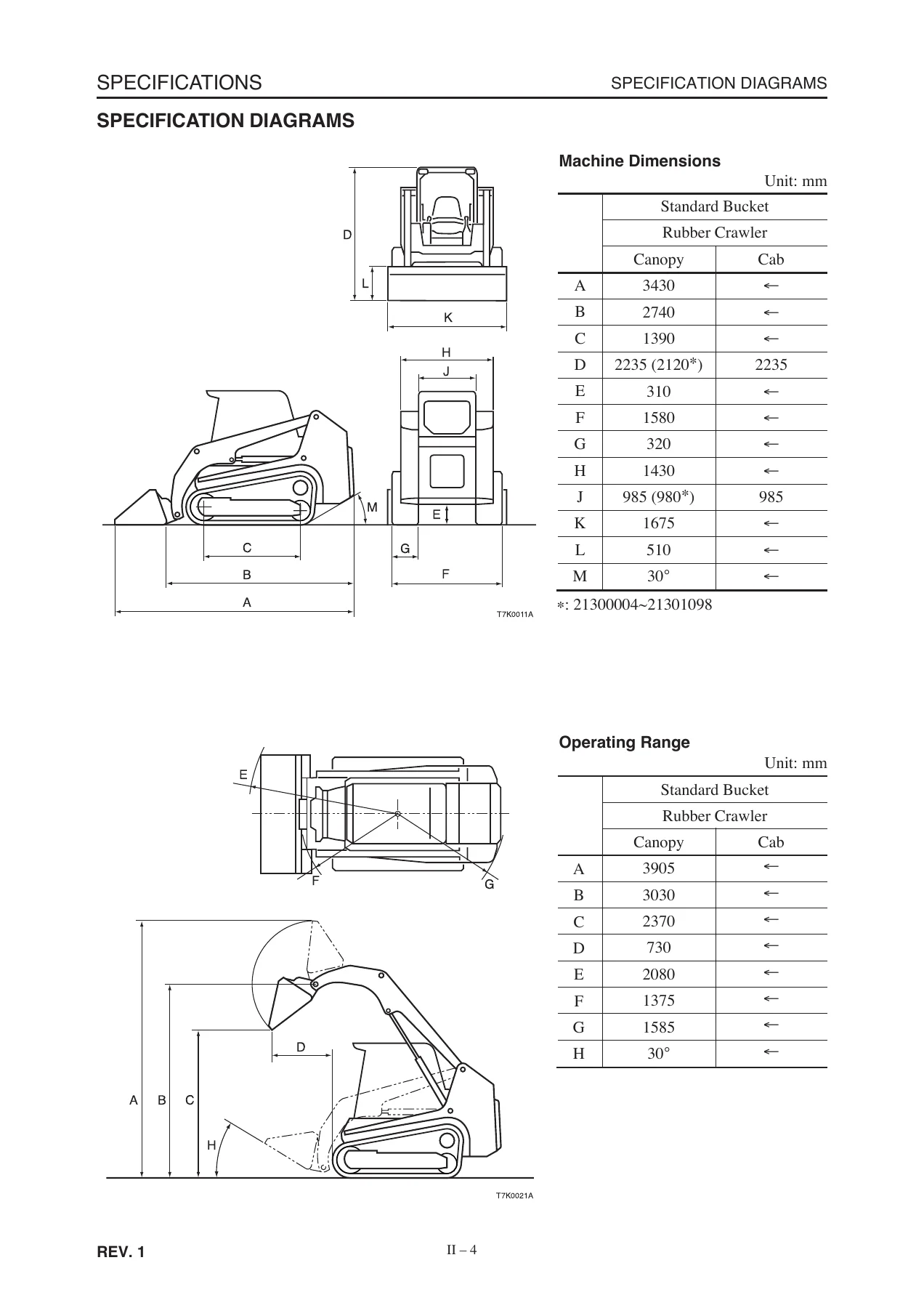
This chapter carries the full specification set: specification diagrams with machine dimensions (overall length, width, height, ground clearance, clearance radii, crawler width, bucket width, departure angle), working range diagrams (maximum lift height to bucket pin, dumping height, dump angle, rollback, reach), specification tables covering rated capacity, machine mass, travel speed, gradeability, ground pressure, tipping load and cycle times, plus the engine, HST pump, gear pump, control valve, sub control valve, pilot valve, auxiliary pilot valve, self-level valve, cylinder and travel motor data. Unit weight (dry mass) tables are broken out by serial range. Recommended lubricants, servicing standards, standards for judging performance and a reference value table with engine speed, hydraulic pressure, travel speed, cylinder speed, natural drop and lever operating force are all provided. A dedicated methods-for-inspecting-performance section explains how to measure travel, lift arm, bucket, charge and pilot pressures, and how to adjust the relief valves.
III. MACHINE CONFIGURATION
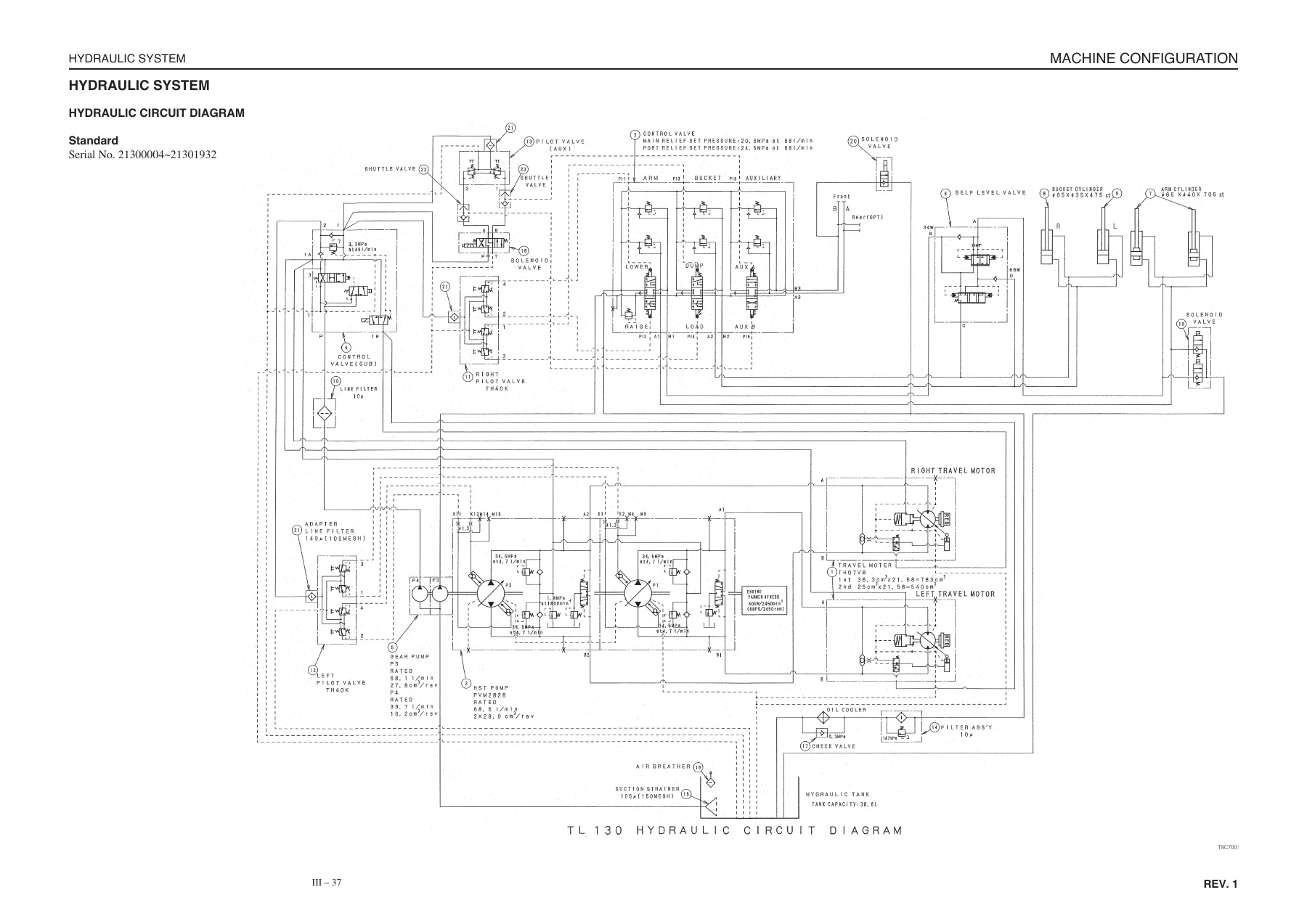
Here the TL130 is broken down by system: the travel system (track roller A and B, idler, track adjuster, travel motor and sprocket with exploded views and torque callouts), the frame and covers, the control system (hydraulic pilot unit, pilot valves, control valve, sub control valve, solenoid valve, HST pump, shuttle valve), attachments (lift arm, quick attachment, bucket, cylinders with pipe routing), the hydraulic system (circuit diagrams for both serial ranges, hydraulic tank, suction pipe, strainer, air breather, sight gauge and an air-bleeding procedure for the pump and cylinders), the electrical system (full wiring diagrams for both serial ranges plus harness, fusible link, fuse and relay layouts), and the air conditioner system.
IV. HYDRAULIC UNITS
This is the teardown and rebuild chapter, and it is deep. It walks through operation, construction, disassembly, assembly, inspection and adjustment for the gear pump, control valve, control valve (sub), pilot valve, pilot valve (auxiliary), self-level valve (both serial ranges), cylinders (arm and bucket), and the travel motor including its 2-speed control valve, parking brake and reduction gears. Each unit gets its own inspection criteria tables, wear limits, service standards and troubleshooting charts. The HST pump section covers the flushing valve, charge check valve, high-pressure relief valve, charge relief valve, servo piston torque adjustment, neutral adjustment, and displacement limiter adjustment. Cylinder work includes special tool dimensions, seal fitting directions, piston nut and set screw torques, natural drop limits and air-bleeding procedures.
V. TROUBLESHOOTING
Rather than a generic fault list, this chapter is organized by complaint. It starts with cautions in troubleshooting and repairs — what to ask the owner, how to reproduce the fault, why to find the true cause before disassembly. Then it moves through overall machine (complete failure of all systems, all systems working but with insufficient power), machine travel (travel train fault, speed falls and machine veers to one side, unusually high travel temperature, will not travel in second speed), lift arms (cylinders fail to move, movement slow or lacks power, momentary drop when slowly pulling the lever, excessive natural drop), and bucket (cylinders fail to move, slow or lacking power, excessive natural drop). Each tree sends you to the correct pressure check, relief valve replacement test, spool inspection, or cylinder leak test, and points back to the relevant section of the manual.
VI. ENGINE
The final chapter covers the Yanmar engine fitted to the TL130 — the 4TNE98-TBL in earlier serials and the 4TNV98-YTBL from 21301933 onward — using the Yanmar TNV series direct injection service material. That includes engine nomenclature and specifications, fuel/lubricating oil/cooling water requirements, periodic maintenance schedules, troubleshooting, complete engine disassembly and reassembly, cylinder head, gear train and camshaft, cylinder block, lubrication system, cooling system, fuel injection pump and governor, turbocharger, starting motor and alternator, electric wiring, service standards and tightening torques for bolts and nuts.
Serial Number and Engine Variant Coverage
Several sections of this manual are split by serial number, and you should confirm your machine’s number against the identification plate before using a value. The main engine break is 21300004~21301932 (Yanmar 4TNE98-TBL) versus 21301933~ (Yanmar 4TNV98-YTBL). Additional sub-ranges include 21300004~21301908, 21300004~21300311, 21300004~21300570, 21300004~21300594, 21300004~21300742, 21300004~21301932, 21301933~21302134 and 21302135~, which affect items such as the engine foot, canopy/cab specification, travel motor mass, quick attachment mass, self-level valve and radiator drain valve. The hydraulic circuit diagrams are also provided separately for 21300004~21301932 and 21301933~.
Why This Manual Matters
The TL130 is a compact crawler loader with a hydrostatic travel system, pilot-operated joystick controls, a self-leveling bucket circuit, and a two-speed piston travel motor with an integrated parking brake. Getting any of those systems wrong — a misadjusted neutral on the HST pump, a self-level valve spool installed backwards, a cylinder rod cover tightened without the correct seal direction, or a relief setting guessed rather than measured — leads to track drift, overheating, cylinder creep, or a machine that will not travel in second speed. This workshop manual gives you the actual set pressures, the neutral adjustment procedure using the M4/M5 and M14/M15 gauge ports, the servo piston rotational torque, the self-level valve flow-split adjustment, and the cylinder natural-drop limits, so the job is done to the same standard the machine was built to. It also carries the full tightening torque system — hydraulic hoses, bite-type pipe fittings, O-ring seal joints, UNF joints and ISO 10.9 bolts and nuts — so nothing gets over- or under-torqued.
IMAGES PREVIEW
Instant PDF Delivery
The Takeuchi TL130 Crawler Loader Workshop Manual is delivered as an instant-download PDF after checkout — no shipping, no waiting, no binder to lose. Open it on a laptop in the shop, a tablet on the machine, or a phone at the parts counter, and print the pages you need for the job in front of you. With 712 pages covering general standards, specifications, machine configuration, hydraulic units, troubleshooting and the Yanmar engine, this is the single reference you keep for the life of the machine.
Reviews
There are no reviews yet.