

Tandy 200 Portable Computer Service Manual 26-3860 – PDF Repair & Schematic Guide
Original price was: $29.95.$17.95Current price is: $17.95.
Complete Tandy 200 (Catalog 26-3860) service manual PDF – disassembly, theory of operation, troubleshooting flowcharts, parts lists, exploded views and full schematic diagrams for the 80C85A-based portable.
Description
Tandy 200 Service Manual – Catalog Number 26-3860
The Tandy 200 Portable Computer is the 40 x 16 character successor to the Radio Shack TRS-80 Model 100, and this service manual is the bench document written for technicians who keep those machines running. It covers the 26-3860 platform from the LCD case down to the DC/DC converter, with the theory, the test points, the part numbers and the schematic sheets needed to diagnose and repair the hardware rather than just describe it.
File Details
- Manual type: Service manual (field and repair-center level)
- Brand: Tandy / Radio Shack
- Model: Tandy 200 Portable Computer
- Catalog number: 26-3860
- Language: English
- File format: PDF
- Page count: 118 pages
- Contents: Seven sections plus three appendices
Chapters Covered
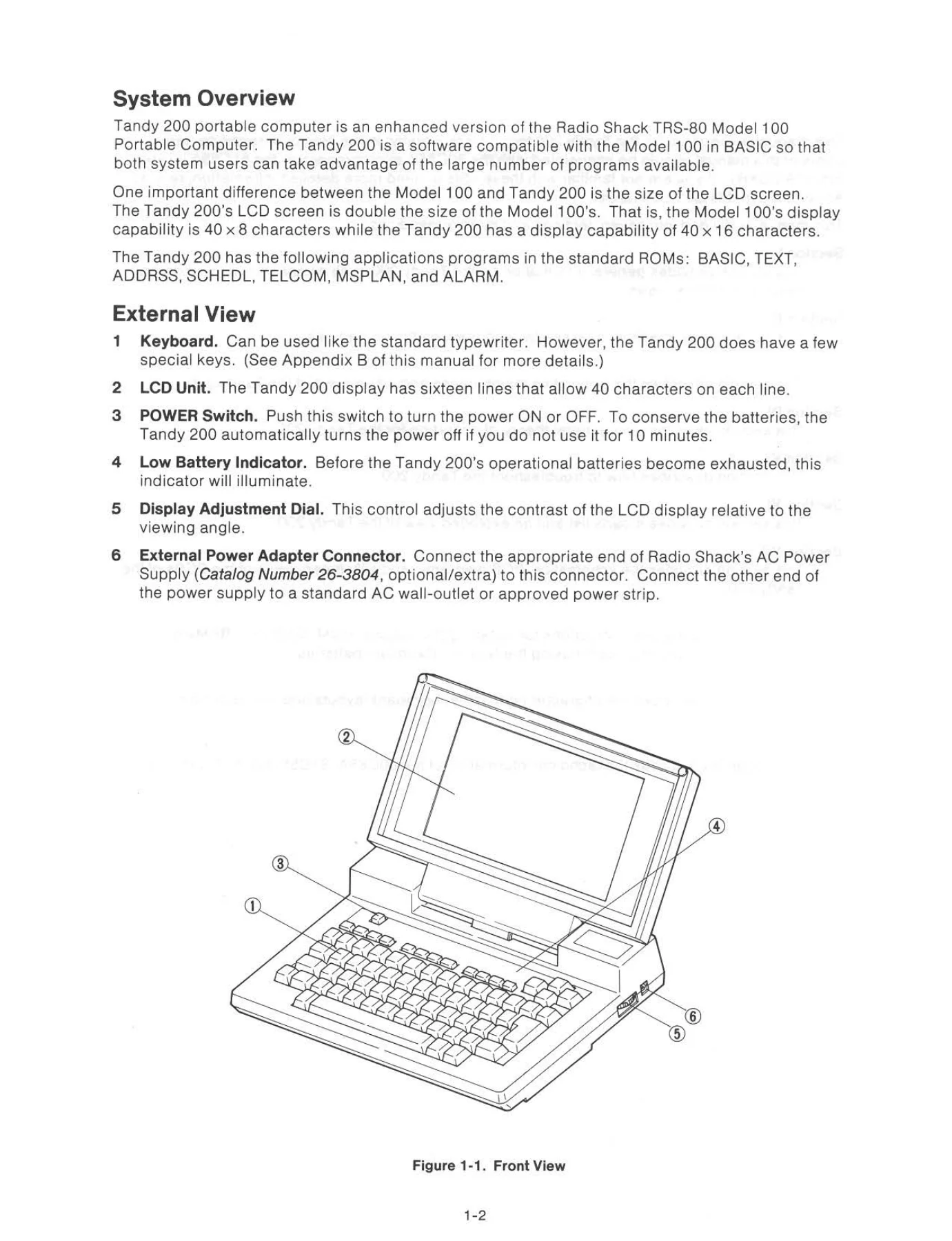
- Introduction – system overview, external view, internal view, specifications
- Disassembly Instructions – LCD case unit, LCD PCB, top case, keyboard PCB, memory PCB, main PCB
- Preventive Maintenance – cleaning the body and LCD display, MODEM transmitting level adjustment
- Theory of Operation – general, block diagram, CPU, memory, address decoding and bank selection, I/O map, keyboard
- Theory of Operation – cassette interface (write, read, remote), printer interface, bar code reader interface
- Theory of Operation – buzzer control, clock control, serial interface, LCD, power supply and auto power ON/OFF
- Troubleshooting – general guidance, troubleshooting guide, checking procedure, check list
- Parts List / Exploded View – main PCB assembly, LCD PCB assembly, memory PCB assembly, keyboard assembly, mechanical and assembly parts
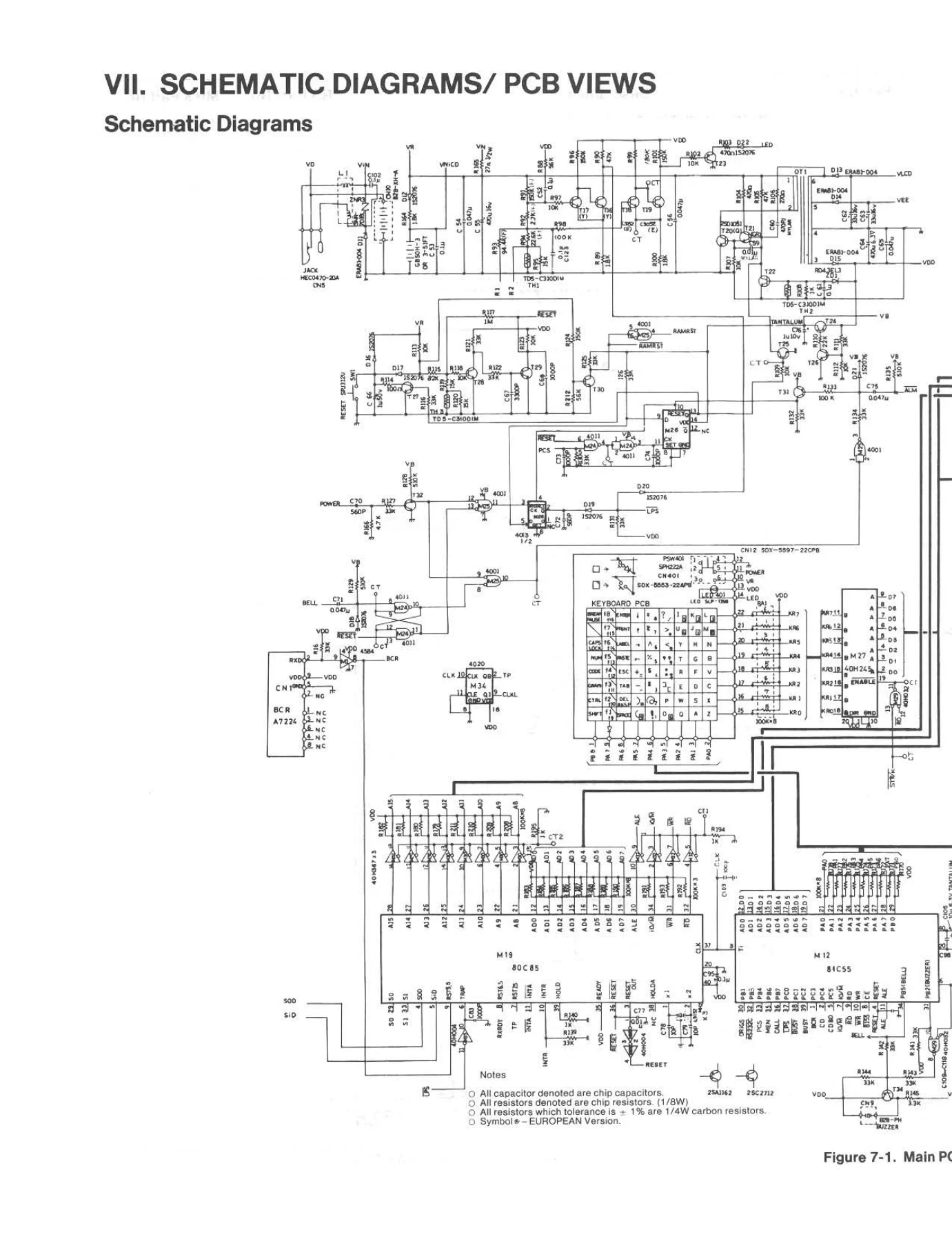
- Schematic Diagrams / PCB Views – main PCB, LCD PCB and memory PCB schematics plus top and bottom PCB views
- Appendix A – installation of optional RAMs and ROM, installation of nickel-cadmium batteries
- Appendix B – keyboard layout, connector pin assignments, character code table
- Appendix C – 80C85A, 81C55, 82C51A and basic construction of the LCD
What the Theory of Operation Section Gives You
Section IV is the core of this Tandy 200 service manual. It walks the whole signal chain in order: the 80C85A CPU running at 2.4576 MHz and how the multiplexed AD0-AD7 bus is split from A8-A15 by the ALE signal inside the SLA5080F0U gate array; the memory map covering the 40K-byte BASIC and application ROM, the 32K-byte MSPLAN ROM and the standard 24K-byte static RAM, plus the optional 32K ROM and dual 24K RAM packages; and the I/O address decoding circuit that assigns the 81C55 PIO, the 82C51A USART, the tone dialer data write, bank selection status, keyboard return and the LCD.
From there it works through the keyboard scan logic with the condition of a pressed “T” key drawn out, the cassette interface split into write, read and remote circuits with each stage shown, the Centronics printer interface and its STROBE / BUSY handshake, the bar code reader input and its RST 5.5 interrupt, the buzzer control circuit for both the BEEP and SOUND commands, and the RP5C01 timer IC that keeps the clock and alarm alive on backup power.
The serial section is covered in unusual depth for a portable of this era – RS-232C/MODEM selection, the RS-232C interface itself, the MC14412 MODEM IC and its peripheral circuit, the transmission filter with its 1200 Hz centre frequency, the three-stage reception filter with separate originate and answer intermediate frequencies, the MODEM connector interface with its RY2 and RY3 relays, and the TCM5089 tone signal generator for pulse and tone dialing.
LCD, Power Supply and Power Sequencing
The LCD chapter explains the HD61830B controller, the HD61103 common drivers and the six HD61100 segment drivers, the 1/64 duty 1/9 bias drive scheme, and the driving waveform for illuminated and non-illuminated dots with the V1 through V6 bias voltage formulas. The power section documents the DC/DC converter built around OT2 and T20/T21, the low power detection circuit that lights the low battery LED at 4.2 V and gives roughly twenty minutes before shutdown, the reset circuit with its RESET and RAMRST signals, and the four separate power-up and power-down paths – the POWER switch, the ALM signal from the timer, and the PCS signal from software.
Disassembly, Troubleshooting and Board-Level Repair
Section II takes the unit apart in the order a technician actually works: LCD case unit, then LCD PCB, then top case, keyboard PCB, memory PCB and finally the main PCB, with the cautions about screw lengths and the reminder that the MODEM switch knob is simply inserted into the slider and easy to lose. Section III covers cleaning and the MODEM transmit level adjustment procedure using a 600-ohm dummy load between pin 3 and pin 7 of CN3, an AC voltmeter, and VR1 trimmed for -14 to -17 dBm on two separate carrier commands.
Section V is a numbered troubleshooting tree with fourteen entry points: no operation at all, wake-up failure, LCD failure, dead keys, buzzer, clock, reset, memory protection, printer, cassette, bar code reader, RS-232C, MODEM and a final system recheck. Each branch names the specific transistors, ICs and connectors to probe, gives the expected supply voltages for VDD, VEE, VLCD and VB, and lists the clock frequencies to confirm. A separate check list walks through wake-up, buzzer and LCD, clock setting, keyboard, warm and cold start, printer, cassette and comms testing.
Parts, Exploded Views and Schematics
Section VI lists capacitors, diodes, coils, integrated circuits, transformers, resistors, variable resistors, crystal oscillators, zener diodes and surge absorbers by reference number with RS part numbers and manufacturer part numbers, alongside an exploded view and the keytop, keyboard, connector and hardware kits. Section VII provides the schematic diagrams for all three PCBs plus top and bottom PCB views. Appendix B gives the full connector pin assignments for the system bus, RS-232C, printer, cassette, MODEM and bar code reader connectors together with the character code table; Appendix C reproduces the manufacturer technical data for the 80C85A, 81C55 and 82C51A with pin configurations, register maps, mode instruction bit assignments and machine cycle charts, plus an explanation of twisted nematic LCD construction and operation.
Who This Tandy 200 Service Manual Is For
This is written for the technician working in the field or in a repair center, and it assumes familiarity with the 80C85A microprocessor, the 81C55 PIO and the 82C51A USART. Anyone restoring a 26-3860, chasing a dead LCD, rebuilding a failed DC/DC converter, replacing the nickel-cadmium backup battery, adjusting the MODEM transmit level or simply replacing a cracked keytop will find the procedure, the value and the part number here.
Why It Matters and How You Get It
IMAGES PREVIEW
Working on a Tandy 200 without the correct reference means guessing at supply rails, bias voltages, filter centre frequencies and connector pinouts – and this machine has four separate supply voltages, three board assemblies and a gate array in the address path, so guessing gets expensive. This Tandy 200 service manual gives you the exact test points, the exact adjustment targets, the exact part references and the actual schematic sheets the unit was built from. Buy the download and the complete 118-page PDF is available immediately after payment – no shipping, no waiting, readable on a laptop, tablet or phone at the bench, and printable if you prefer paper schematics next to the unit while you work.



Reviews
There are no reviews yet.