
Toshiba Nemio 10 20 30 Diagnostic Ultrasound Service Training Manual
Original price was: $49.95.$29.95Current price is: $29.95.
Service training material for Toshiba Nemio 10, Nemio 20 and Nemio 30 diagnostic ultrasound systems, covering system configuration, transducers, operation and presets, peripherals, disassembly, circuit-board functions, power supply architecture, software handling, service diagnostics, logs, backup/restore functions and troubleshooting procedures.
Description
The Toshiba Nemio 10 20 30 Diagnostic Ultrasound Service Training Manual provides technical service training and system-reference material for the Nemio diagnostic ultrasound platform. It identifies the three Nemio models, explains differences in configuration and upgrade paths, and then moves into operation, hardware architecture, board-level functions, disassembly, software handling, diagnostic service functions and troubleshooting. The material is particularly useful when a technician needs to understand how major assemblies interact, gain access to replaceable hardware, run built-in diagnostics, review service information or trace faults through the system.
File Details
- Manual type: Service training material
- Brand: Toshiba
- Models: Nemio 10, Nemio 20, Nemio 30
- Language: English
- Page count: 168 pages
- File format: PDF
Nemio System Coverage
The training begins by distinguishing the three system versions. Nemio 20 and Nemio 30 are presented as color units, while Nemio 10 is shown as a B/W unit. The Nemio 10 standard configuration includes a B/W abdominal system, two active transducer connectors, a 12-inch interlaced B/W monitor, B/W printer mounting kit, built-in floppy disk drive, a 63-frame image memory kit, peripheral cables and a local language kit. Options shown for Nemio 10 include a third transducer connector for linear/convex probes, built-in magnetic optical disk drive, PWD, 255-frame image memory, footswitch, THI, ECG/PCG and IDUS as a future-release item.
The material also describes system upgrade relationships. Nemio 10 can be upgraded to Nemio 20 using the UIUG-551A upgrade kit, whose composition is shown as the CFPR PWB, ECDC PWB, color monitor, peripheral unit rack, MO drive with accessories and THI disk. Installation time is stated as about four hours. Nemio 20 can be upgraded to Nemio 30 with upgrade kit UIUG-550A.
Transducers, Controls and Presets
The Toshiba Nemio 10 20 30 Diagnostic Ultrasound Service Training Manual includes a substantial operational section because service work on these systems requires familiarity with the control panel, presets and configuration menus. The material covers the main and sub panels, trackball-centered operation, exchangeable key-tops, programmable controls, pop-up menus and user-function key assignments.
Connectable M- and F-series transducers shown for the first release include PLM-1204AT, PLM-1202S, PLM-703AT, PLM-805AT, PLF-308P, PSM-20CT, PSM-25AT, PSM-37AT, PSM-50AT, PSM-70AT, PSM-37CT, PVM-375AT, PVM-575AT, PVM-662AT, PVF-381MT, PVM-651VT, PVM-740RT, PVL-715RT, PVF-745V, PEF-510MA, PC-19M, PC-50V, PVF-738H, PVF-738F, PLM-503AT, PVF-620ST and PEF-708FA. Probe categories illustrated include sector, convex, linear, endovaginal/endorectal, multiplane TEE and pencil transducers.
Preset coverage includes system configuration, special configuration, time correction, scale set, image-process presets, needle-adapter settings and exam presets. The exam-preset material includes region selection, condition settings, measurement-item registration, auto-measurement registration, OB items and hospital-name settings. Separate procedures explain custom key registration and returning system settings to factory preset defaults.
Peripherals and External Connections
Peripheral coverage includes video recorder, color printer, B/W printers and the system I/O panels. The Sony SVO-9500MD(P) video recorder is discussed together with remote-control requirements and service preset communication settings. The Mitsubishi CP-770DW SCSI digital color printer is also covered, including the system setting used to enable the SCSI color printer. Rear-panel illustrations identify connections for audio, S-video, VGA, RGB, Ethernet, USB, VCR remote, serial and SCSI functions, along with workstation-related connections.
Disassembly and Hardware Access
A major section of this Nemio service training material is devoted to physical access and disassembly. Illustrated procedures show how to reach the rear PWB rack, access the PSEL, PCNT and ECG boards, remove the main panel, remove the monitor, take off the side covers and foot-rest, reach the power-supply assemblies, remove the MO drive and remove the Mother PWB.
The PWB rack is shown as containing ten boards. Main-panel removal includes access to the CTPN panel-control board, main-panel PWB, sub panel and replaceable rotary encoders. Power-supply disassembly identifies five field-replaceable units: the RGLT regulator PWB, PWX power transformer, SWRG switching regulator, HVPS high-voltage power supply and LNF line filter. Step-by-step illustrations show removal of the SWRG PWB, HVPS PWB, RGLT PWB and line filter, including prerequisite disassembly where required.
System Architecture and Board-Level Functions
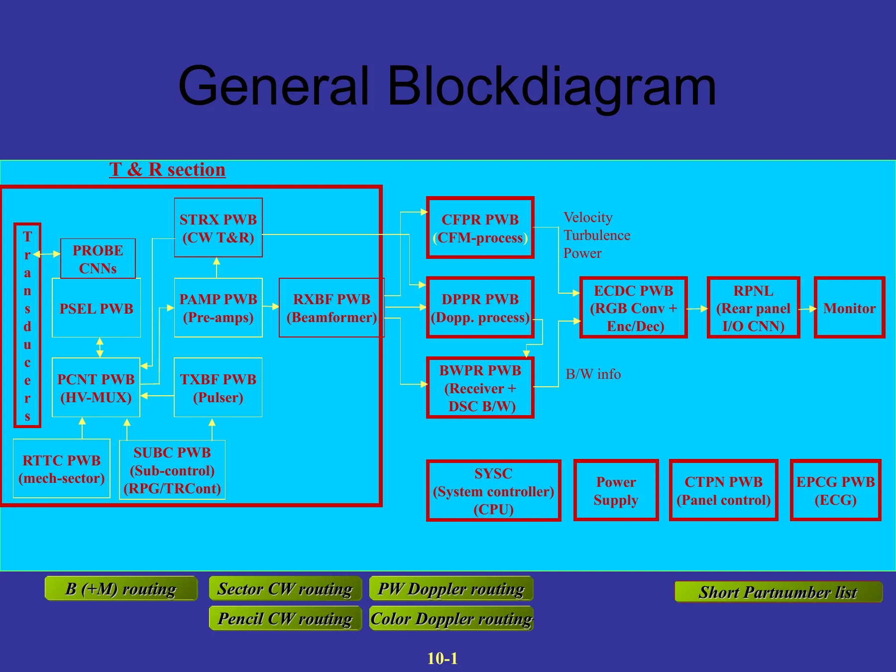
The hardware section uses block diagrams, board photographs and functional explanations to trace signal flow through the ultrasound system. A general block diagram identifies the transmit/receive section, probe connectors, PSEL probe selector, PCNT probe control, TXBF transmit beamformer, PAMP pre-amplifier, RXBF receive beamformer, BWPR black-and-white processor, CFPR, DPPR, ECDC encoder/decoder, RPNL rear-panel board, SUBC sub-control board, SYSC system-control board, power supply, CTPN panel control and EPCG ECG/PCG board.
Separate diagrams cover B(+M) routing and the T&R section. The PSEL explanation details probe selection, relay switching and connector arrangements. The PCNT section explains its interface role between the Mother PWB and PSEL PWB, its high-voltage switches, HVSW multiplexer control and fault-detection functions for high-voltage leakage and over-high-voltage conditions. The TXBF section describes transmission of 64 high-voltage pulses, Z-converter power, HVSW multiplexer control and high-voltage fault detection.
The PAMP section explains echo pre-amplification and the differences between configurations with and without phased-array sector and CW options. RXBF coverage explains A/D conversion, digital receive delay and the use of RXBF A and B with phased-array sector probes versus RXBF B with linear/convex probes. The BWPR chapter describes receiver functions such as echo filtering, log amplification and detection, echo enhancement, AGC and DR, together with DSC functions including persistence, lateral filtering, M-Max processing, image memory and M-mode image memory.
The ECDC board section covers combining B/W and color information into RGB signals, interlaced and non-interlaced analog RGB conversion, color-bar generation, video encoding/decoding and video selection. Video specifications are also included. The RPNL section explains its role as a connector board for video, audio and control signals and identifies the RPNL JIG service tool, part number 55400ARPJG.
Additional board explanations cover SUBC control functions, the SYSC CPU board, EPCG ECG/PCG processing and the CTPN control-panel interface. The SYSC section identifies Flash ROM system software, LAN, USB, serial, floppy-disk and SCSI control, real-time clock and a RISC SH4 microprocessor. Procedures are included for SYSC replacement-related configuration and Nemio 10 compatibility settings.
Power Supply and Software Handling
The power-supply diagrams trace AC input through the line filter, transformer and switched regulator to the regulator and high-voltage supply. Input values shown include 100, 115 or 230 V, with additional transformer information for 100/120 V and 220/240 V configurations. The training identifies regulator outputs and illustrates the individual power-supply assemblies, including HVPS outputs shown as HV+185V and HV-12V.
Software handling explains that system software is stored in Flash ROMs on the SYSC PWB. System or optional software can be loaded from MO or floppy disks. The version-up procedure includes inserting the appropriate media, powering the system while holding the FREEZE button and allowing the software to load automatically. The material states that loading from MO takes about 10 minutes, while loading from floppy disks on Nemio 10 takes about half an hour.
Service Diagnostics and Maintenance Functions
The built-in service software is a central part of this manual. The maintenance section covers site, system, hardware/software and configuration information; error logs and service history; diagnostic self-tests; backup and restore of user data; optional software installation; and monitor color-adjustment patterns. The system information section also includes an inspection-schedule function that can produce a preventive-maintenance message after 600 hours of system use when activated.
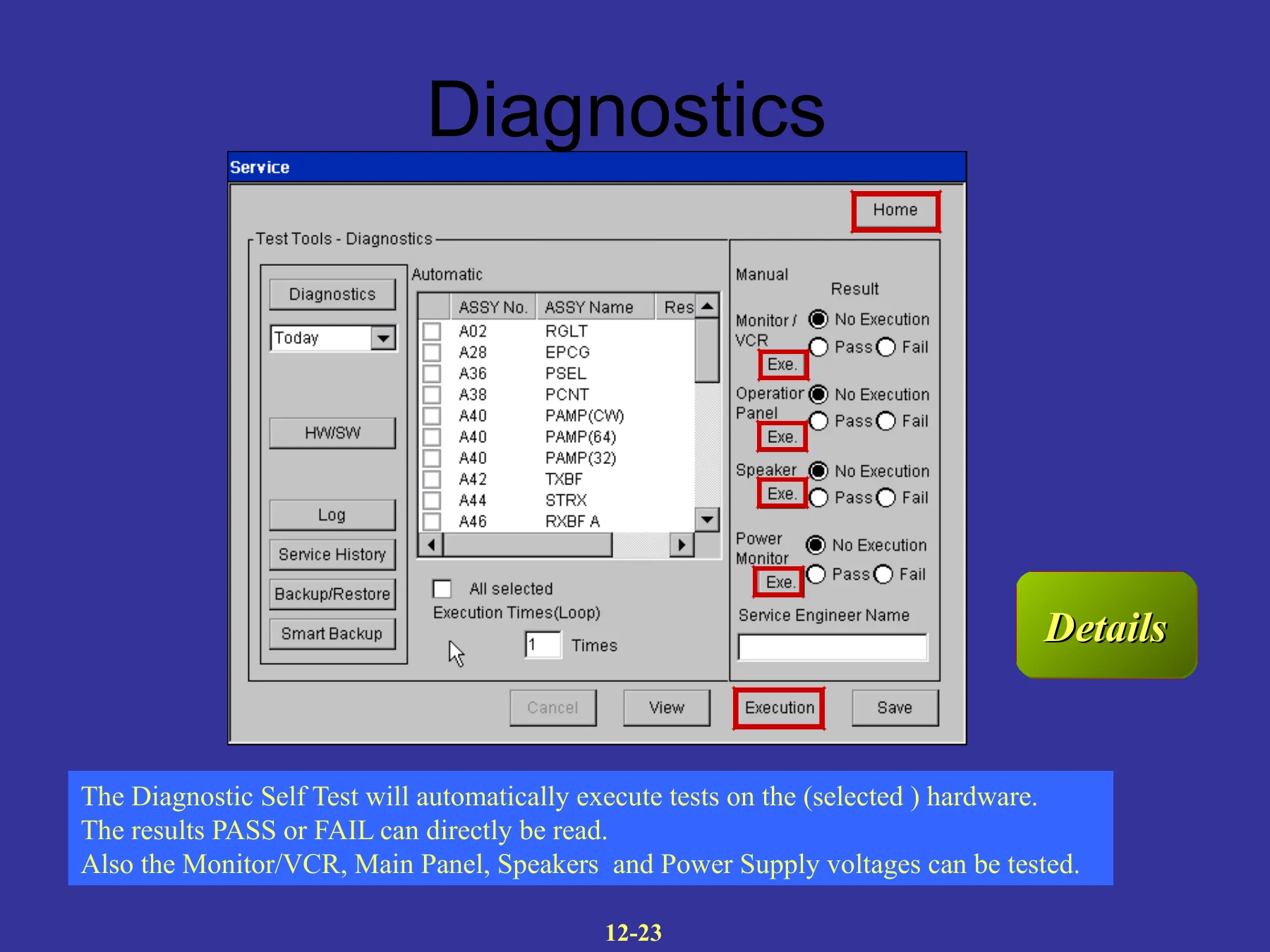
Diagnostic self-tests can be run on selected hardware with PASS or FAIL results. The training also shows tests for the monitor/VCR, operation panel, speakers and power-supply voltages. It states that the diagnostic tests take about four minutes and describes prompts that appear during testing, including switching on the lamp beneath the monitor and connecting an array transducer to port A.
Service logs include the Key History Log, Error Log, system use time and transducer use time. The Key History Log can store 1000 key strokes for analysis of bugs or system hang-ups, with results downloadable to MO or floppy. The Image Data Viewer allows intermittent failure images stored by the customer to be reviewed by the service engineer. System Test Results and System Maintenance Results can also be retained and transferred. Service History fields support preventive or corrective maintenance records, hardware/software/probe classifications, recurrence information and service completion status.
Chapters Covered
- Nemio system introduction and model differences
- Nemio 10, Nemio 20 and Nemio 30
- M- and F-series transducers
- Operation panel and image storage features
- Standard configurations and options
- Nemio 10 configuration
- Image memory, PWD, THI, ECG/PCG and other options
- Transducers
- Sector, convex and linear probes
- Endovaginal/endorectal, multiplane TEE and pencil probes
- Upgrades
- Nemio 20 to Nemio 30
- Nemio 10 to Nemio 20
- Easy operation
- Main and sub panel operation
- Pop-up menus and system presets
- Custom keys and factory defaults
- Peripherals
- Video recorder
- Color and B/W printers
- I/O panels
- Disassembly
- PWB rack and probe-control boards
- Main panel, monitor, covers and foot-rest
- Power-supply parts, MO drive and Mother PWB
- System hardware and block diagrams
- Transmit and receive routing
- PSEL, PCNT, TXBF, PAMP and RXBF boards
- BWPR, ECDC, RPNL, SUBC and SYSC boards
- EPCG, CTPN and power-supply circuits
- Software handling
- Flash ROM software
- MO and floppy software loading
- New service functions
- Service information and configuration
- Diagnostic self-tests
- Logs, service history and failure-image viewing
- Backup/restore and color-adjustment patterns
- Troubleshooting
- Power-supply troubleshooting
- Minimum system configuration
- Probe Selector test
- PAL/NTSC setting
- Nemio reset procedure
- Miscellaneous reference
- Workstation functions
- Hardware codes
- Backup/Restore file details
- Nemio 10/20/30 probe-port arrangements
Taken as a whole, the document combines operating familiarity with detailed service access, signal-flow explanations, component identification, diagnostic software and troubleshooting. It allows a technician to move from identifying a Nemio configuration through accessing internal boards, understanding the function of key PWBs, checking service logs and diagnostic results, and isolating faults such as power-supply or probe-path problems.
Service and Troubleshooting Reference
For practical fault work, the training includes a dedicated troubleshooting section. Power-supply diagnosis starts with the 3.3 V rear-panel indicator and explains how its state can help narrow the suspected fault to the RGLT PWB, SWRG, line filter or transformer. The Power Monitor function can automatically measure DC voltages. A minimum operating hardware configuration is identified as SYSC PWB, ECDC PWB, SUBC PWB and RPNL PWB.
The Probe Selector test provides a specific procedure using a convex probe, preferably PVM-375AT, along with service configuration and TESTPRO functions. The accompanying signal-flow diagram states that the receive circuits of the PSEL, PCNT, PAMP and RXBF PWBs are tested, while the probe and relay switches themselves are not. The troubleshooting material also provides commands for switching between PAL and NTSC operation and gives the key combination used to reset the Nemio without a normal power-off/power-on cycle.
Use the Toshiba Nemio Training Manual for Service Work
The Toshiba Nemio 10 20 30 Diagnostic Ultrasound Service Training Manual supports technicians working on system configuration, internal hardware access, PWB replacement, signal-path understanding, power-supply diagnosis, software loading, service-menu operation, self-test execution, log review and system troubleshooting. Having the correct Nemio board functions, service procedures, menu paths and diagnostic references together is especially useful when fault isolation depends on understanding how several assemblies interact rather than replacing parts without a defined test path.
IMAGES PREVIEW
The manual is supplied as an instant PDF download after purchase. There is no physical shipping. The PDF can be opened on compatible computers, tablets and phones and can be printed for workshop or service-bench reference.
Reviews
There are no reviews yet.