
Toyota 8FBES15U 8FBE15U 18U 20U Forklift Repair Manual Volume 2 – Controller, Display & Troubleshooting PDF
Original price was: $39.95.$23.95Current price is: $23.95.
Toyota 8FBES15U, 8FBE15U, 8FBE18U, 8FBE20U and 8FBEH18U forklift Repair Manual Volume 2 in PDF. Covers the controller system, multi-function display, complete diagnosis code troubleshooting and the wiring/connector appendix – 703 pages of Toyota electric forklift service procedures.
Description
File Details
- Manual type: Repair Manual (Service Manual), Volume 2
- Brand: Toyota
- Models covered: 8FBES15U, 8FBE15U, 8FBE18U, 8FBE20U, 8FBEH18U
- Language: English
- Page count: 703 pages
- File format: PDF
- Document date: September 2015
- Publisher: Toyota Material Handling Company, A Division of Toyota Industries Corporation
This is the second volume of the Toyota service documentation for the 8FBE15U to 20U series. Where Volume 1 handles the mechanical side of the truck, this volume is dedicated entirely to the electrical and electronic control architecture – the main controller, the motor drivers, the display, and the diagnostic logic that ties them together. For anyone servicing a Toyota 8FBES15U, 8FBE15U, 8FBE18U, 8FBE20U or 8FBEH18U electric forklift, this is the volume that explains how the truck thinks, how it reports faults, and how to bring it back into specification.
Chapters Covered
- Controller – General, Electrical Components Layout Drawing, Layout of Controller Cables, Specifications, Components, Before Inspection, Connector Inspection, Disassembly Procedure, Main Controller, Drive and Pump Motor Driver, Contactor Panel (Standard), Contactor Panel (UL-EE Specification), Fan, Display, Combination Switch, Accelerator Sensor (Potentiometer), Brake Sensor (Potentiometer), Brake Switch Adjustment, OCL Measurement
- Display – General, General Functions, Service Functions, Multi-function Display ASSY
- Troubleshooting – Before Troubleshooting, SST, Diagnosis Code List, When Error Code Is Displayed, When No Error Code Is Displayed
- Appendix – SST List, Service Standards, Connector Drawing, Electric Wiring Diagram
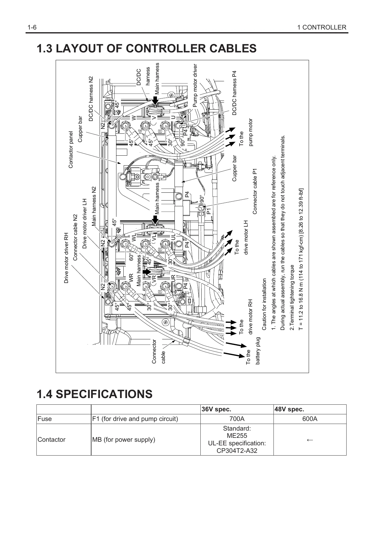
Read together, those four chapters form a complete electrical service path. The Controller chapter opens with system configuration and the CAN communication layout that links the main controller, drive/pump motor drivers and multi-function display, then walks through component locations, cable routing, board-level connector pin assignments, and the disassembly sequence for the main controller, motor drivers, contactor panels and cooling fans. It also covers the peripheral input devices – combination switch, accelerator potentiometer, brake potentiometer and stop lamp switch – with adjustment values and matching procedures.
What the Controller Section Gives You
The connector inspection chapter is where most real-world diagnosis starts. Toyota lists the SST shorting harness (09230-13240-71 for CN101 to CN104), the conditions for each measurement, and the standard voltage or resistance expected at every pin on CN101, CN102, CN103 and CN104, split between Conventional Lever and Mini Lever variants. Accelerator and brake potentiometer signal voltages, lift and tilt lever neutral voltages, attachment lever outputs, seat switch state, parking brake switch, direction switch and the CAN1H/CAN1L lines are all documented with the expected readings, so a technician can trace a fault back to a specific wire or sensor rather than guessing at a board replacement.
The main controller and motor driver sections cover removal and installation with torque values, connector pin assignments, and the DC/DC converter, cover and bracket sequence. The contactor panels are treated separately for the Standard and UL-EE specifications, including the F1 fuse selection, fuse installation direction and lapping sequence, the harness angles, and an insulation resistance test procedure that must be carried out after reassembly. The fan section, combination switch disassembly, accelerator and brake sensor calibration, and the OCL measurement procedure for the drive circuit close out the chapter.
Display and Service Functions
The Display chapter explains the multi-function display that first appeared with CAN communication on this model change. It covers the initial screen after key-on, the status indicators (OPS, parking brake, low speed turtle, spanner, overheat, battery discharge level, speedometer, power meter, direction and mast tilt), and the administrator-level settings reached with a password. The service functions section is the part a working technician will live in: analyzer (DIAG MEMORY, DIAG MEMORY QR, I/O TEMP/VOLT, I/O TRAVELING, I/O M.HANDLING, I/O STEERING, I/O OTHERS, ACTIVE TEST, VERSION), tuning menus for travel and material handling behaviour, option set menus for specification configuration, matching procedures for the accelerator, brake, SAS, lever and OCV systems, and the others menu for meter start, demo mode, default set, service password and LCD contrast.
Diagnosis Codes and Wiring
The Troubleshooting chapter is built around a full diagnosis code list and then a step-by-step page for every code. It covers controller, driver, motor, sensor, solenoid, contactor, communication and display faults with probable causes, related circuit diagrams, measurement terminals and judgment tables. Alongside the codes it explains connector handling, wire harness and connector inspection, short circuit testing and the SSTs used for accurate troubleshooting. When no error code is displayed, the manual includes a phenomena-based table that maps vehicle behaviour – vehicle does not run, load handling cannot be performed, steering is heavy, OPS does not operate, buzzer and auxiliary equipment faults – to likely failed portions and the correct check.
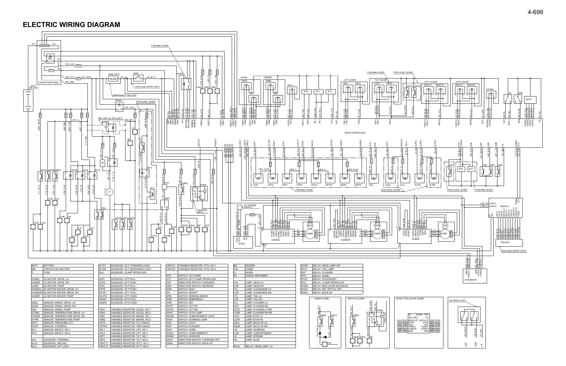
The Appendix is where the heavy reference material sits: the SST list, service standards for the controller, accelerator potentiometer and brake potentiometer, a connector drawing covering the whole truck harness, and the complete electric wiring diagram with a connecting diagram. Those two large schematic pages are the ones you will keep open while tracing a fault through the truck.
Who This Volume Is For
This is the volume for the technician who already has the truck on the bench or in the bay and needs the electrical answers rather than the mechanical ones. It is written around Toyota’s own service procedures and specifications, which means the diagnostic logic, matching routines, connector standards and torque values are the ones the truck was designed to be serviced with. Fault finding on a CAN-based AC electric forklift without the correct reference voltages and matching procedures is slow work; with this manual in hand, a controller fault, a communication error between a motor driver and the main controller, a potentiometer drift or a stored diagnostic code can be worked through in sequence instead of by parts swapping.
Because this is Volume 2, it should be used alongside Volume 1 for any job that crosses between the mechanical and electrical systems. The content in this file is dedicated to the controller, display, troubleshooting and appendix material only.
Why This Manual Matters
Toyota’s controller system on the 8FBE15U to 20U series uses microcomputer-assisted inverter control with CAN communication between the main controller, the drive and pump motor drivers, and the multi-function display. The pump motor driver also handles power steering, and the display now sits on the CAN bus, which is what enables features such as the PIN code entry system and shock sensor. That architecture means the correct diagnostic code, the correct matching value and the correct connector pin voltage are not optional extras – they are the difference between a repair that holds and a fault that comes back. This manual gives you those values in the form Toyota published them.
IMAGES PREVIEW
Instant PDF Delivery
The Toyota 8FBES15U, 8FBE15U, 8FBE18U, 8FBE20U and 8FBEH18U forklift Repair Manual Volume 2 is delivered as a PDF download immediately after purchase. There is no shipping and nothing to wait for. The file can be viewed on a laptop, tablet or phone in the workshop, searched for a specific diagnosis code or connector number, and printed for the pages you want on the bench. If you service Toyota electric forklifts, keeping the controller, display and troubleshooting volume on hand is the fastest way to move from a fault code to a fixed truck.
Reviews
There are no reviews yet.