
Toyota 8FGF 8FDF15-30 Forklift Troubleshooting and Wiring Manual CE112 2015
Original price was: $39.95.$23.95Current price is: $23.95.
Toyota 8FGF/8FDF15-30 Troubleshooting and Wiring Manual (CE112, 2015) — 549-page PDF covering error code diagnostics and complete electrical wiring diagrams for 4Y, 1DZ-II, 1DZ-III, and 1ZS engine forklifts.
Description
Toyota 8FGF 8FDF15-30 Forklift Troubleshooting and Wiring Manual — CE112
This Toyota 8FGF 8FDF15-30 Forklift Troubleshooting and Wiring Manual (Publication No. CE112, dated January 2015) is the diagnostic companion for the 8FGF and 8FDF 15 through 30 series forklifts. It combines the complete error code troubleshooting procedures with the full electrical wiring diagrams, making it the reference technicians reach for when a fault code appears on the combination meter or when a circuit needs to be traced from fuse to ground. The manual covers gasoline, LPG, and diesel engine variants, with dedicated troubleshooting paths for the 4Y, 1DZ-II, 1DZ-III, and 1ZS engines.
File Details
- Manual type: Troubleshooting and Wiring Manual
- Publication number: CE112
- Edition/date: January 2015 (1st Printing)
- Brand: Toyota Industrial Equipment / Toyota Material Handling Company
- Models covered: 8FGF15~30, 8FDF15~30 series forklifts
- Engines covered: 4Y, 1DZ-II, 1DZ-III, 1ZS
- Language: English
- Pages: 549
- File format: PDF
Chapters Covered
- 1 TROUBLESHOOTING
- 1.1 Before Troubleshooting — connector handling, wire harness and connector inspection, continuity inspection, short circuit check, visual and contact pressure checks
- 1.2 Diagnosis Code List — detection ECUs (SAS/OPS, DISP, METER, ENG, ASC), error code tables with indication, memory, spanner, and detection ECU columns
- 1.3 Warning List — wrench lamp and OPS lamp warnings, overheat, high/low battery voltage, swing lock control, tilt restrictions
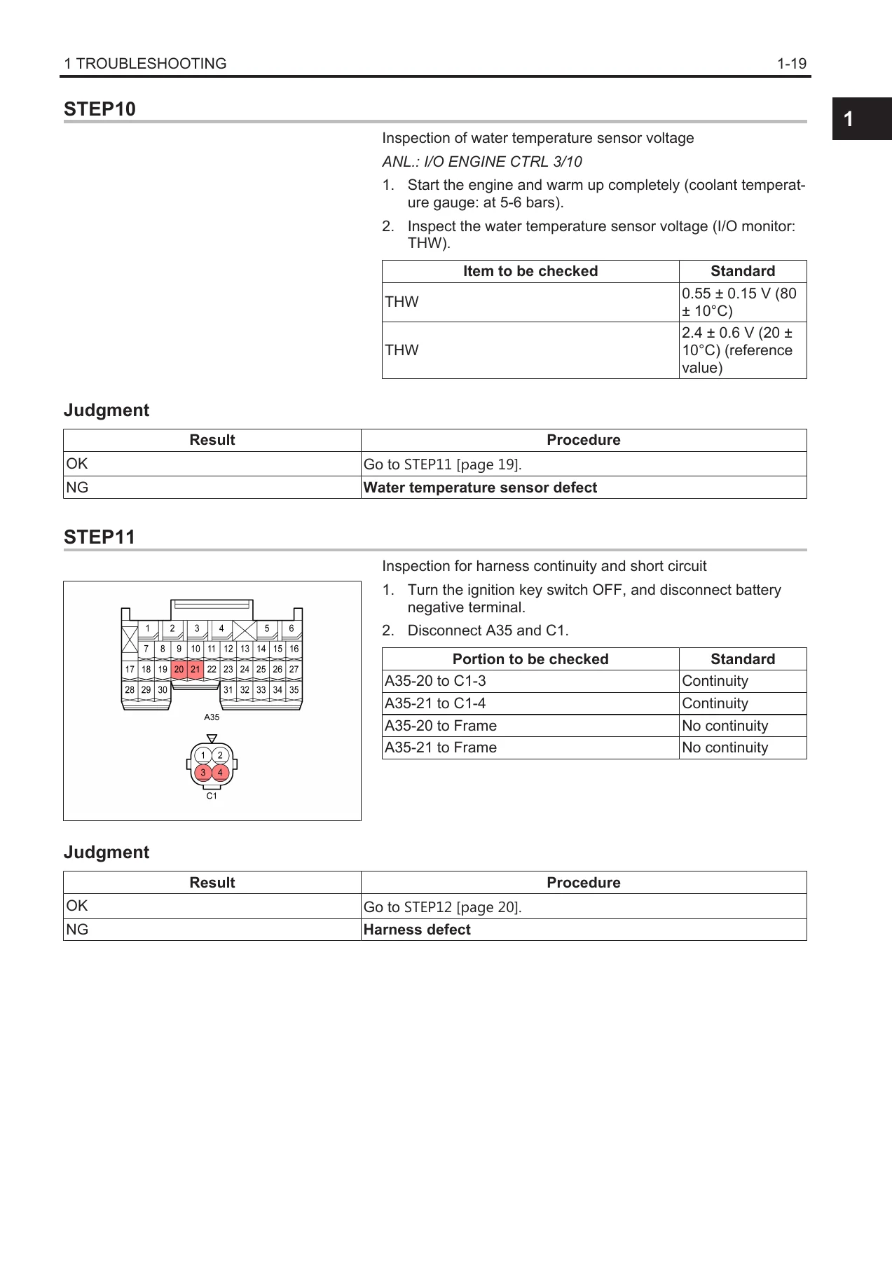
- 1.4 When Error Code Is Displayed — step-by-step troubleshooting for every code with connector diagrams, resistance/voltage standards, and judgement tables
- 1.5 When No Error Code Is Displayed
- 1.6 Error Code List — engine diagnosis code comparison table (1ZS)
- 2 WIRING DIAGRAM
- 2.1 Introduction — how to read electrical wiring routings, relay locations, system circuits, ground points, fuses for power supply, connector list, abbreviations, glossary of terms and symbols
- 2.2 Electrical Wiring Routings — engine room (4Y-E, 4Y-M, 1DZ, 1ZS), instrument panel, front body, mast area, rear body (No.1 and No.2)
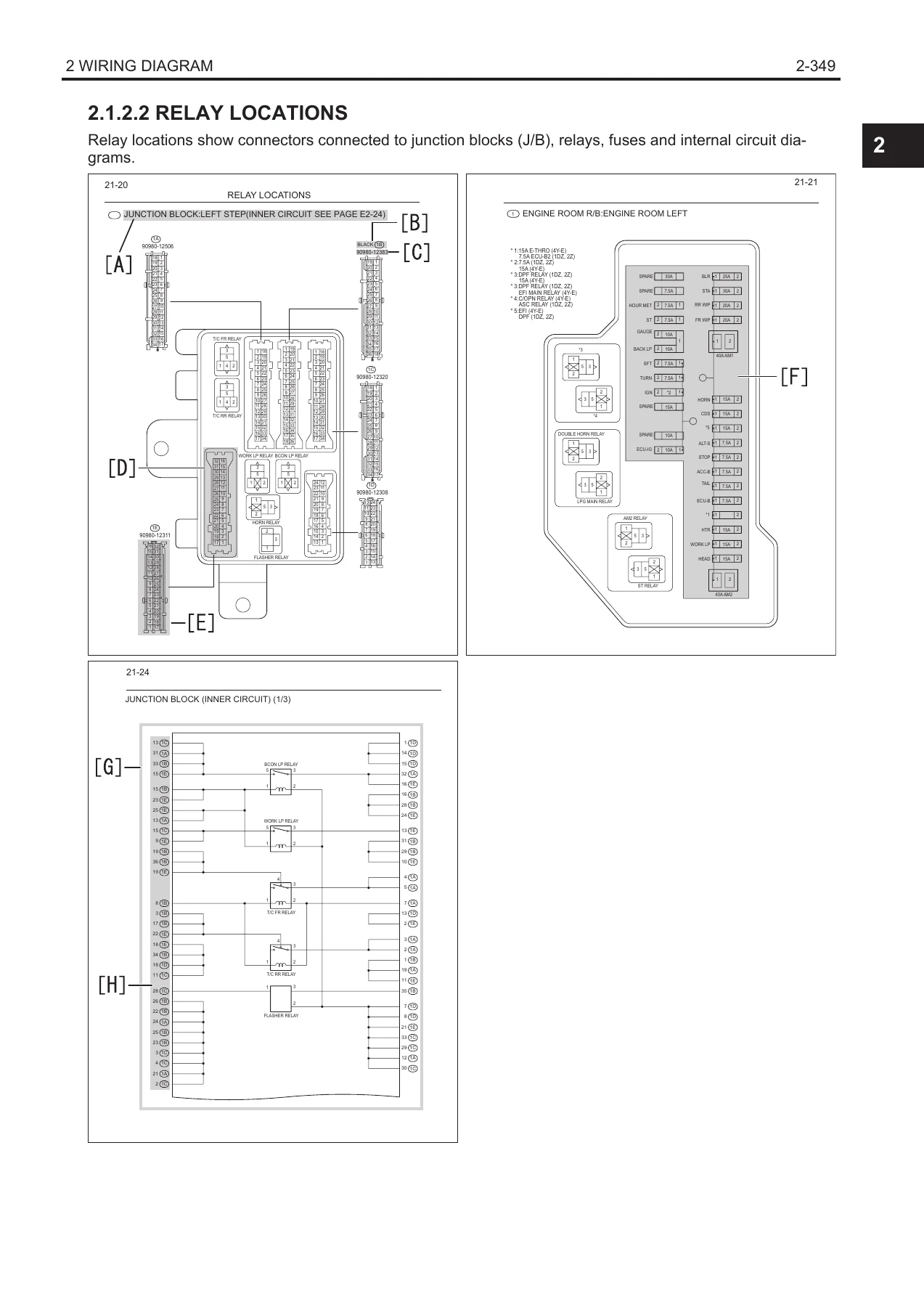
- 2.3 Relay Locations — fusible link block assy, engine room R/B, J/B, CAN joint connector, junction connectors, inner circuit diagrams
- 2.4 System Circuit — power source, engine, chassis, body, instrument panel, lighting system, heater system, communication system
- 2.5 Ground Points
- 2.6 Fuses for Power Supply
- 2.7 Connector List
The troubleshooting section walks through every stored fault code — from fuel feedback control errors on the 4Y engine through common rail pressure faults on the 1ZS diesel — with step-by-step inspections, connector reference diagrams, resistance and voltage standards, and judgement tables that tell you exactly what a good reading looks like versus a defective component. Each error code entry names the probable cause, shows the related circuit diagram with connector pinouts, and ends with a clear OK/NG judgement path.
The wiring diagram section is equally thorough. System circuits cover the complete electrical architecture: power distribution from the fusible link block through the engine room relay block, the engine control circuits for each engine family, the SAS/OPS system, power shift transmission, EZ pedal, working lamps, lighting, wipers, heater, and CAN communication. Wiring routings show harness positions, ground point locations, and connector numbers for the engine room, instrument panel, front body, mast area, and rear body. Relay locations include internal circuit diagrams for the J/B and CAN joint connector.
Diagnostic Error Codes Covered
The Toyota 8FGF 8FDF15-30 troubleshooting manual’s error code list spans the full range of systems on these forklifts. Engine-related codes include fuel feedback control, intake air temperature and pressure sensors, water temperature sensor, throttle position sensor with motor, electronic throttle, fuel control module, ignition signal, fuel specification determination, air flow meter, atmospheric pressure sensor, fuel temperature sensor, EGR position and motor, variable nozzle turbocharger, crank and cam position sensors, common rail pressure, supply pump, and EDU/injector circuits. SAS/OPS codes cover the matching connector, speed sensor, yaw rate sensor, swing lock solenoid, load sensor, tilt angle sensor, tilt switches, lift lower lock solenoid, tilt control solenoid, lifting height switch, lift switches, backward tilt lock solenoid, tire angle sensor, steering-wheel angle sensors, knob position compensation solenoid, seat switch, brake switch, and CAN communication errors. ASC codes cover motor relay, NMR switch, idle switch, and crank position sensor. Accelerator pedal position sensor codes for both engine ECU and ASC variants are included, along with multi-function display and combination meter error codes.
Wiring Diagrams and Electrical Systems
Every system circuit in this Toyota forklift wiring manual is drawn with wire colours, connector codes, terminal numbers, and junction block references so you can trace a circuit from the battery positive terminal through fuses, relays, switches, and components to the ground point. The power source section shows power distribution from the fusible link block and engine room relay block to every fused circuit. Engine control diagrams are separated by engine family so you can work on the 4Y gasoline/LPG system, the 1DZ-II and 1DZ-III diesel systems, or the 1ZS common rail diesel without wading through irrelevant circuits. The CAN communication diagrams show the twisted wire pairs and joint connectors for the 4Y-E, 1ZS, 1DZ, and 4Y-M networks.
Ground point tables and fuse-to-system tables make it quick to identify which ground or fuse feeds a faulty circuit — particularly useful when a code points to a sensor but the real problem is a shared ground or blown fuse. The connector list at the end of the wiring section gives connector shapes, terminal numbers, part numbers, and colours for every connector referenced in the diagrams.
The relay locations chapter includes design drawings and internal circuit diagrams for relays, relay blocks (R/B), junction blocks (J/B), fusible links (F/L), and junction connectors (J/C). This lets you test a relay in place or identify which internal junction block circuit a wire belongs to before disassembling anything.
Why This Manual Matters for 8FGF/8FDF15-30 Owners and Technicians
Diagnosing a forklift fault code without the correct procedure wastes time and risks replacing good components. This Toyota 8FGF 8FDF15-30 troubleshooting manual gives you the exact inspection sequence for each code, the voltage and resistance standards to measure against, and connector pinout diagrams so you can identify the right terminal every time. The wiring diagrams let you trace circuits visually rather than guessing at harness routing, and the connector list ensures you order the correct replacement terminals and housings.
For workshops maintaining mixed fleets of 8FGF and 8FDF 15 to 30 series forklifts, this manual covers all four engine variants in a single volume. You get the diagnostic logic for the SAS/OPS system, the engine control systems, the transmission and EZ pedal circuits, lighting, wipers, heater, and CAN communication — all in one place. The step-by-step judgement tables mean even a complex intermittent fault can be isolated methodically.
Whether you are chasing a spanner lamp on a 4Y-powered LPG truck, diagnosing a common rail pressure fault on a 1ZS diesel, or tracing a short in the lighting circuit, this manual provides the procedures and reference data to get the job done correctly.
Get Instant Access to the Toyota 8FGF/8FDF15-30 Troubleshooting and Wiring Manual
IMAGES PREVIEW
This CE112 manual is delivered as an instant PDF download — no shipping, no waiting. Open it on any computer, tablet, or smartphone, print the pages you need for the workshop, and keep the full manual on hand for every diagnostic session. With 549 pages of troubleshooting procedures, wiring diagrams, connector data, and system circuits covering the 8FGF and 8FDF 15 through 30 series forklifts, it is a practical reference that earns its place in any service department or owner-operator’s tool collection.
Reviews
There are no reviews yet.