
Volvo Penta 8.1Gi-B/C/D/E/F & 8.1GXi-A/B/C/D/E Engine Workshop Manual 7743378 (2004)
Original price was: $32.95.$18.95Current price is: $18.95.
Workshop manual VPA 7743378 (10-2004) for Volvo Penta 8.1 liter Gi-B/C/D/E/F and GXi-A/B/C/D/E stern-drive engines. Covers engine mechanical overhaul, steering, throttle and shift cables, cooling, engine R&I, tune-up, storage, and troubleshooting.
Description
Volvo Penta 8.1Gi-B/C/D/E/F & 8.1GXi-A/B/C/D/E Engine Workshop Manual 7743378 (2004)
This workshop manual is written for the Volvo Penta 8.1 liter gasoline stern-drive engines identified on the cover as 8.1Gi-B/C/D/E/F and 8.1GXi-A/B/C/D/E. Publication marking throughout the book is VPA 7743378 10-2004. The book is the engine volume: mechanical rebuild, power steering, throttle and shift cables, raw-water and closed cooling, engine removal and installation, plus general service, storage, and safety. It is not the separate EFI diagnostic book or the Electrical/Ignition/Fuel service manual that the text points to when ignition modules, injector diagnostics, or fuel-cell pump testing are required.
File Details
- Manual type: Engine workshop manual
- Brand / models: Volvo Penta 8.1Gi-B, 8.1Gi-C, 8.1Gi-D, 8.1Gi-E, 8.1Gi-F, 8.1GXi-A, 8.1GXi-B, 8.1GXi-C, 8.1GXi-D, 8.1GXi-E
- Language: English
- Page count: 260
- File format: PDF
- Document number / date: VPA 7743378, 10-2004
- Cover marking: Workshop Manual, Engine, C 2(0)
What These 8.1 Liter Engines Are
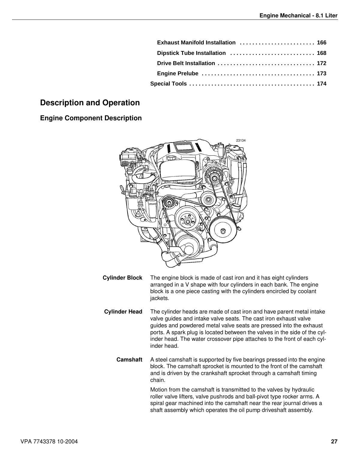
Section 2 describes a cast-iron V8 with four cylinders in each bank and coolant jackets cast around the bores. Displacement is given as 8.1 L / 496 CID, bore 107.950 mm (4.250 in.), stroke 111.00 mm (4.370 in.), compression ratio 9.1:1, firing order 1-8-7-2-6-5-4-3, and spark-plug gap 1.52 mm (0.060 in.). The crankshaft is cast nodular iron on five bearings, with the number-five rear bearing carrying thrust. A powdered-metal crankshaft-position reluctor is pressed onto the rear of the crankshaft.
Two piston constructions appear in the same book. On 8.1Gi-B/C/D/E and 8.1GXi-A/B/C/D the piston pin is a floating fit in the piston and a press fit in the forged-steel rod; the piston and rod are serviced only as an assembly. On 8.1Gi-F and 8.1GXi-E the pin is full-floating and retained by two snap rings in the piston. Both families use coated pistons with two compression rings and one oil-control ring. The later F/E specification block also lists RPO L18 and VIN G.
The valve train is ball-pivot with hydraulic roller lifters, tubular pushrods, and 1.70:1 rocker arms. Lifters hold net lash, so the manual does not call for periodic valve-clearance adjustment. Cylinder heads are cast iron with parent-metal intake seats and pressed powdered-metal exhaust seats. The intake manifold is one-piece cast aluminum carrying the throttle body, an eight-injector fuel rail, and a MAP sensor. PCV is a fixed orifice cast into the manifold; there is no serviceable PCV valve.
Chapters Covered
- General Information — Tuning the Engine; Engine Compression Testing and Test Conclusion; Ignition and Fuel System Components; Intake Manifold Vacuum Testing; Gasoline Requirements and Gasoline Containing Alcohol; Crankcase Oil; Draining and Filling the Engine Crankcase; Steering System Lubrication; Power Trim/Tilt Fluid Level; Off-Season Storage; Preparation for Boating After Storage; Engine Break-in; Submerged Engine; 20-Hour Check; Belt Tension; Positive Closed-Type Ventilation System; Troubleshooting — System Isolation and Engine Troubleshooting Guides
- Engine Mechanical – 8.1 Liter — Description and Operation (engine components, pistons and connecting rods, lubrication); Replacing Engine Gaskets; Use of RTV and Anaerobic Sealer; Diagnostic Information & Procedures (base engine, engine noise, valve train, drive-belt chirp/squeal/whine/rumble/vibration/fall-off/wear/tensioner); Specifications 8.1Gi-B/C/D/E, 8.1GXi-A/B/C/D; Specifications 8.1Gi-F, 8.1GXi-E; Repair Instructions from draining fluids through drive belt, balancer, flywheel, pilot bearing, dipstick, exhaust manifold, coolant crossover, circulation pump, intake manifold, rocker covers, cylinder heads, lifters, oil pump drive, oil pan, oil pump, front cover, timing chain and sprockets, camshaft, pistons and rods, rear seal, crankshaft, oil-filter adapter, block plugs, and cam bearings; clean/inspect, cylinder boring and honing, bearing measurement, valve-guide reaming and seat grinding, reassembly through engine prelube; Special Tools
- Steering System — Special tools; Power Steering System description, pump and system operation, pump removal and installation; Hydraulic fluid, level check, air purge, belt adjustment; Steering cylinder removal, servicing, installation; Cable installation; Lubrication and hoses; System diagnosis, twin-engine tie-bar adjustment, diagnosis chart
- Throttle & Shift Control System — Installation of shift and throttle cables; Check remote-control shift-cable stroke; Installation of SAE cables to engine/drive; Throttle cable to engine; Neutral start switch tests (electrical and mechanical); Removal of SAE remote-control cables from engine and sterndrive
- Cooling System — Raw-water cooled engines; Closed cooling engines; Cooling system troubleshooting and isolating a cooling problem; Hoses, clamps, drain plugs, thermostat, manifolds and elbows, circulating pump, supply pump, impeller removal and installation; Draining engine block or exhaust manifold and supply pump; Thermostat replacement; Sterndrive and transom-bracket cooling schematic; 8.1 Gi/GXi and 8.1Gi/GXi (F) engine cooling diagrams
- Engine Removal and Installation — Special tools and sealants; Engine removal; Exhaust pipe replacement; Engine installation and alignment; Connect exhaust hose, throttle cable, and fuel supply; Rear engine mounts; Determining minimum engine height
- Safety — Part A: marine products and people who use them (shift, throttle, steering, fuel and electrical); Part B: marine products and people who fix them (handling engines, lead-acid batteries, gasoline, hazardous products)
Taken together, the Volvo Penta 8.1Gi-B/C/D/E/F & 8.1GXi-A/B/C/D/E Engine Workshop Manual 7743378 (2004) is the book a shop uses to keep the 8.1 liter block, heads, valve train, cooling circuit, steering pump and cylinder, and control cables inside published limits. Tune-up order, compression and vacuum interpretation, oil and fuel rules, winterization, break-in, and system-isolation charts sit in Section 1 so a technician can decide whether the next step is a mechanical teardown or a referral to the EFI or electrical manuals.
Service Limits and Workshop Data Printed in the Book
Fastener and engine tables are split by suffix. Table 13 (Gi-B/C/D/E and GXi-A/B/C/D) and Table 15 (Gi-F and GXi-E) give metric and English tightening values, including angle-torque sequences. Examples from the earlier group: connecting-rod nut 30 Nm + 90° (22 ft. lb. + 90°); crankshaft balancer bolt 255 Nm (189 ft. lb.); main-bearing cap bolts first pass 30 Nm then 90°; cylinder-head bolts first pass 30 Nm, second pass 30 Nm + 120°, then a final angle that changes with long, medium, and short bolts; flywheel bolts 100 Nm (74 ft. lb.); oil-pump bolt 75 Nm (56 ft. lb.); spark plugs 20 Nm (15 ft. lb.).
Lubrication figures in Table 14 include oil capacity without a filter change of 7.57 liters / 8.0 US quarts (the general-information capacity table also lists 9.0 qts / 8.5 liters with filter). Minimum oil pressure is listed as 34 kPa (5 psi) at 1000 r/m and a maximum figure of 69 kPa (10 psi) at 2000 r/m in that same table; the oil-pressure diagnosis text also cites a high-rpm check of 166 kPa (24 psig) minimum at 4000 RPM. The oil pump is gear driven and the filter is full flow.
Cylinder-bore production diameter is 107.950–107.968 mm (4.2500–4.2507 in.), with a 0.030 in. oversize bore of 108.712–108.7298 mm. Crankshaft main-journal diameter for journals 1–4 is given as 68.805–69.822 mm in Table 14 and 69.805–69.822 mm in the F/E table; crankpin diameter is 55.854–55.870 mm. End play, bearing clearances, cam lobe lift, and valve face/seat angles (45° face, 46° seat) are tabulated so a machine shop can accept or reject parts without guessing.
Fuel, Oil, Storage, and Break-In Rules
The book specifies unleaded gasoline only: inside the U.S. minimum (R+M)/2 AKI = 87, outside the U.S. minimum RON = 90. It warns that octane 86 AKI (89 RON) and lower is treated as misuse. Ethanol is limited to no more than 10% when the boat fuel system is compatible; methanol is prohibited. Factory fill is API Service SH. Multi-viscosity oils such as 10W-30 or 10W-40 are not recommended for this marine application. Viscosity is chosen by lowest anticipated temperature: SAE 30 at 32°F (0°C) and above, SAE 20W-20 from 0°F to 32°F, SAE 10 below 0°F. Synthetic Volvo Penta oil is on a 200-hour or annual drain; other oils are 100 hours or annual. Oil is withdrawn through the dipstick/withdrawal tube so it does not drain into the bilge.
Off-season storage is a nine-step sequence that includes a stabilizer-plus-two-cycle-oil storage mix run at about 1500 RPM, oil and filter change, sterndrive lubricant change to GL-5 synthetic 75W-90, cooling-system drain with the engine level, and (carbureted models only) fogging. Electric fuel pumps must not be run dry more than 20 seconds. Break-in is the first 20 hours, with staged throttle use and a mandatory oil and filter change at the end; factory break-in oil is not to be dumped early. The 20-hour check list covers oil, trim fluid, fuel filter, flame arrestor, steering ram grease, shift system, exhaust clamps, belts, mounts, and sterndrive oil.
Cooling, Steering, Controls, and Engine Swap
Raw-water engines use a crankshaft-driven impeller supply pump and a centrifugal circulating pump. Closed-cooling layouts and separate Gi/GXi versus Gi/GXi (F) flow diagrams are included. Drain-plug reinstall torque after winterizing is given as 29 N·m (22 lb. ft.). Power steering uses Volvo Penta Power Trim/Tilt & Steering Fluid (GM power-steering fluid or Dexron II also accepted), with pump service, cylinder rebuild, cable anchor-nut torque of 120 in. lb. (14 N·m), and a twin-engine tie-bar procedure. Shift-cable pull/push direction is specified by propeller rotation on SX and DP-S drives. Engine R&I covers when the sterndrive must come off (less than 6 in. / 15.2 cm bulkhead clearance), alignment tool 3851083-0, and minimum engine height so water cannot run back into the manifolds.
Diagnostics You Can Run From This Volume
Section 1 compression testing disables ignition by unplugging the crankshaft-position sensor and disables injectors by pulling relay F3, then cranks at wide-open throttle. The lowest cylinder must be within 75% of the highest; a worked example uses 140 PSI high / 105 PSI low, and Table 1 lists matching min/max pairs. Vacuum at idle is expected at 14–19 in. Hg (47–64 kPa), with a gauge-pattern table for late timing, leaks, worn rings, sticking or burned valves, weak springs, restricted exhaust, and head-gasket leak. Symptom charts cover will-not-crank, cranks-no-start, cold and hot hard start, rough running, noises and vibration, overheat, dies-out, will-not-reach-RPM, lubrication faults, and low battery after storage. Drive-belt diagnosis in Section 2 separates chirp, squeal, whine, rumble, vibration, belt throw, wear, and tensioner faults. Serpentine belts on fuel-injected models are not tensioned; replace when the indicator lines up with the single mark on the housing.
Use This Manual to Complete the Job Correctly
The Volvo Penta 8.1Gi-B/C/D/E/F & 8.1GXi-A/B/C/D/E Engine Workshop Manual 7743378 (2004) supports cylinder-head and short-block work, bearing and ring measurement, cam and timing-chain service, cooling-system drain and impeller replacement, power-steering pump and cylinder work, cable rigging, engine alignment after a swap, seasonal storage, and first-principles diagnosis of compression, vacuum, oil pressure, and belt noise. Published torque sequences, bore and journal limits, oil and fuel rules, and cooling diagrams keep a 496-cid marine V8 from being assembled or winterized by guesswork. After payment you receive an instant PDF download — no shipping wait — that you can open on a shop computer, tablet, or phone and print the pages needed on the bench.

Reviews
There are no reviews yet.