
Volvo Penta D4 D6 Electrical Systems Workshop Manual Group 30 47704208 2019
Original price was: $27.95.$16.95Current price is: $16.95.
Group 30 electrical workshop manual for Volvo Penta D4 and D6 marine engines covering sensors, EVC/EDC fault tracing, measurements, VODIA parameters, and wiring diagrams through generation F. Publication 47704208, January 2019.
Description
Volvo Penta D4 D6 Electrical Systems Workshop Manual Group 30 47704208 2019
This Group 30 workshop manual is written for technicians working the electrical and electronic control side of Volvo Penta D4 and D6 marine diesel engines. Publication 47704208 (English, 01-2019) gathers sensor specifications, engine-protection limits, EVC handling rules, MID 128 fault-code diagnosis, break-out measurements, VODIA log ranges, and generation-specific wiring diagrams in one electrical package rather than a full mechanical overhaul book.
File Details
- Manual type: Workshop Manual, Group 30 Electrical Systems
- Brand / models: Volvo Penta D4 and D6
- Document number: 47704208
- Cover marking: B 2(0), D4/D6
- Date: January 2019 (01-2019)
- Language: English
- Page count: 122
- File format: PDF
Who This Manual Is For
The opening pages state that the book is produced primarily for Volvo Penta workshops and assumes trade-standard mechanical and electrical skill. It is not a complete engine rebuild manual. Mechanical overhaul, injection-pump setting, and air/exhaust hardware changes sit outside Group 30. What it does give is the electrical path from connector and bus checks through ECU pin-level diagnosis on engines using EDC7C / EDC7C1, PCU, HCU, CAN, and J1587.
Engine generations A, B, C, D, E, and F are called out where software and wiring differ. Inactive-code erase rules change at generation F and around delivery week W1319 / Data set II. Twelve-volt installations include a DC/DC converter that also feeds EVC; twenty-four-volt layouts substitute a fuse arrangement shown on the later schematic.
Chapters Covered
- 00-0 General — product identity, spare-part and certified-engine notes, repair instructions, lock nuts, sealants, fluorocarbon-rubber safety
- 03-3 Specifications, Electrical — sensor and switch data, alternator and starter ratings, low-idle adjustment, Engine Protection Map
- 05-1 Safety Instructions — warning hierarchy, electrical isolation, batteries, fuel-system jet hazards, welding and wash limits
- 08-2 Special Service Tools — 885675 break-out cable, 88820047 VODIA, 88890074 multimeter, 9998699 break-out box, 88890117 break-out cable
- 30-0 General — pre-diagnosis connector checks, EVC power rules, erasing fault codes, CAN and J1587 network notes
- Fault tracing of cables and connectors — open-circuit and short-circuit resistance checks, contact oxidation, bus-cable 120 Ω CAN H–CAN L test
- Checking alternator brushes (3587218 and 3840182), starter-motor voltage drop, charging-system output tables
- Rail pressure measurement with voltage-to-MPa conversion table
- Electrical welding — ECU and alternator isolation sequence
- Fault-code structure — MID, PID, PPID, SID, PSID, FMI table
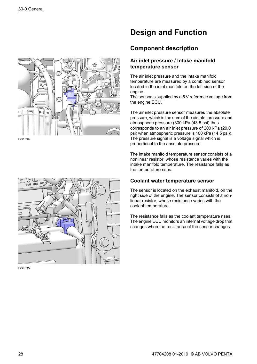
- Design and Function — component locations and operation for inlet pressure/temperature, coolant and fuel temperature, cam and flywheel sensors, oil pressure, water-in-fuel, rail pressure, coolant-level reed switch, stop relay, voltage converter, MPROP valve, 50 A / 20 A circuit breakers
- 30-2 Fault Tracing — MID 128 codes from coolant level through injectors, MPROP, PRV, booster voltages, exhaust-manifold water temperature, and data-link faults
- Measurements — break-out box connection, sensor circuit checks, camshaft/engine-speed sensor, coolant-level switch, supercharger clutch and solenoid
- VODIA Log Parameters — oil, boost, barometric and rail pressure; intake, coolant and fuel temperature; ECU battery potential; throttle positions
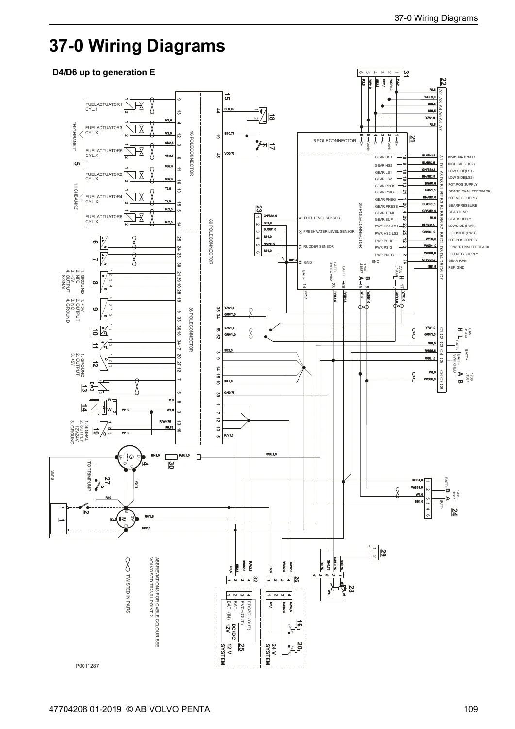
- 37-0 Wiring Diagrams — D4/D6 up to generation E; D4/D6 from generation F including injector pin-out on the EDC7C 16-pin connector
- 39-0 General — MID 128 index, alphabetical index, service-bulletin reference sheet
IMAGES PREVIEW
Taken together, the Volvo Penta D4 D6 Electrical Systems Workshop Manual Group 30 47704208 2019 is a diagnosis and measurement book: it tells a technician which sensor lives where, what voltage or resistance to expect, which FMI meaning applies, and how the harness is drawn for the generation on the bench.
Electrical Specifications and Protection Limits
Section 03-3 lists working ranges used throughout later tests. The oil-pressure sensor is a 5 V linear unit, 0–700 kPa, 3-pin, 30 Nm. Rail pressure is 5 V linear, 0–180 MPa. The combined air-inlet pressure / intake-manifold temperature sensor is 5 V, 4-pin, 50–400 kPa and −40 °C to +130 °C, 20 Nm. Coolant and fuel temperature sensors are 2-pin NTC devices, −40 °C to +150 °C, 30 Nm. Exhaust-manifold water temperature uses a Pt-200 element at 25 Nm. Crank and cam speed sensors are inductive, 2-pin. Water-in-fuel is a 12 V / 24 V 3-pin switch at 2 Nm. Coolant level is a 2-pin reed switch.
Charging and starting hardware is given as 14 V / 28 V alternators at 115 A / 80 A and 12 V / 24 V starters at 3.6 kW / 5.0 kW. Low idle may be set to 700–750 rpm on D4 and 600–650 rpm on D6.
The Engine Protection Map states alarm and derate thresholds: air-inlet pressure alarm at 350 kPa with no derate; coolant-temperature soft derate from 96 °C (100 % torque) to 105 °C (50 % remaining torque); fuel-temperature system derate at 60 °C after a 12-second delay; intake-manifold temperature alarm at 60 °C; exhaust-manifold water temperature alarm at 90 °C. Oil-pressure alarm and derate steps rise with speed from 50 kPa at 300 rpm to 250 kPa at 4000 rpm, with a 2-second delay before system derate. System derate leaves only limited torque available.
Diagnosis, Measurements, and Networks
Before any sensor is condemned, the 30-0 procedure requires connector inspection for oxidation and bent pins, then a reconnect test. Some codes go inactive with the engine stopped, so a running check is specified. EVC work demands the main switch off and keys at 0 before ECU connectors are opened. Help-start boosters are forbidden; only batteries may be used.
Inactive codes erase after five ignition cycles on generations A–E and on generation F units delivered before W1319 that still lack Data set II. After Data set II, and on engines delivered from W1319, erase takes fifty ignition cycles.
Cable work uses resistance at +20 °C on a cold, isolated engine: near 0 Ω for continuity, infinite for isolation between conductors. CAN H to CAN L measures about 120 Ω toward the engine ECU or the PCU when the opposite node is still connected. Rail-pressure diagnosis with break-out cable 885675 starts at 0.5 V (0 MPa) with key on; injection is not enabled until rail pressure reaches at least 20 MPa (2900 psi). A full voltage-to-pressure table runs from 0.5 V / 0 MPa to 4.5 V / 180.0 MPa.
Charging checks include brush wear to a 5 mm limit on alternators 3587218 and 3840182, a 0.2 V maximum drop on starter and charge cables, and current-output floors versus alternator speed at 13.5 V and 27.0 V. Welding instructions isolate the three ECU connectors and all alternator leads, with the ground clamp kept off bearings.
Fault codes follow SAE MID / PID / SID / FMI numbering. MID 128 is the engine control unit. The index maps coolant level, accelerator position (PID 91), water in fuel (PID 97), oil pressure (PID 100), intake temperature (PID 105), air-inlet pressure (PID 106), barometric pressure (PID 108), coolant temperature (PID 110), ECU battery potential (PID 158), injection control pressure (PID 164), fuel temperature (PID 174), engine speed (PID 190), injectors SID 1–6, cam and crank timing (SID 21 / 22), MPROP monitoring (PSID 50), PRV monitoring (PSID 53), booster voltages, and J1939 / MID 187 data-link faults to the matching diagnosis pages.
Wiring Diagrams
Two complete engine harness drawings are included. The generation E sheet identifies battery, main switch, starter, alternator, injectors, RPM and cam sensors, boost/temperature, oil, coolant, fuel and rail sensors, high-pressure pump, supercharger, EDC7C1, 20 A auto fuses, PCU, customer and diagnosis connectors, voltage converter, 50 A fuse, stop relay, fire-extinguisher connector, and HCU. The generation F sheet adds the 24 V fuse that replaces the DC/DC converter, ABYC exhaust-temperature wiring, and an injector map on the EDC7C 16-pin connector for cylinders 1–6. Cable-color keys and default 0.75 mm² conductor size are printed with each drawing.
Use This Manual For Electrical Repair Work
With the Volvo Penta D4 D6 Electrical Systems Workshop Manual Group 30 47704208 2019 on the bench you can isolate a no-start caused by low rail pressure, chase a yellow or red alarm to the matching MID 128 FMI, measure a 5 V sensor circuit through the break-out box, verify CAN termination, inspect alternator brushes, and read the correct generation harness without guessing pin functions. Correct tightening torques, protection-map limits, and voltage tables keep a certified engine inside the electrical specification the control unit expects.
Delivery is an instant PDF download after payment. There is no printed shipment to wait for. Open the file on a workshop PC, tablet, or phone and print the wiring sheet or measurement table you need for the job.
Reviews
There are no reviews yet.