
Volvo Penta EVC-C3 Workshop Manual Group 30 Electrical System – D3-D16 Diesel & Gas Engines
Original price was: $39.95.$24.95Current price is: $24.95.
Complete Volvo Penta EVC-C3 Workshop Manual for Group 30 Electrical System, covering D3-D16 diesel and gas engines. Includes fault tracing, wiring diagrams, component descriptions, and diagnostic procedures for the EVC system.
Description
Volvo Penta EVC-C3 Workshop Manual Group 30 Electrical System
This Volvo Penta EVC-C3 Workshop Manual covers Group 30 Electrical System for D3-D16 diesel engines and gas engines. It is the comprehensive service and repair guide for the Electronic Vessel Control (EVC) system used across these engine platforms, providing technicians and boat owners with the technical data, descriptions, maintenance, and repair instructions needed to diagnose and service the complete electrical architecture.
The EVC system is a distributed network of electronic control units (nodes) that manage engine speed, gear shifting, steering, instrumentation, and vessel functions. This manual breaks down every node, connector, cable, and sensor within that network, supported by detailed fault tracing procedures and wiring diagrams. Whether you are troubleshooting a fault code, replacing a control unit, checking a potentiometer, or tracing a CAN bus communication problem, this manual gives you the exact measurements, pin configurations, and step-by-step actions required.
File Details
- Manual Type: Workshop Manual
- Brand: Volvo Penta
- Model/System: EVC-C3 (Electronic Vessel Control)
- Group: 30 Electrical System
- Engine Coverage: Diesel engines D3-D16, Gas engines
- Engine Designations: B, C, D, E 2(0)
- Language: English
- Document Number: 47700749
- Edition/Date: 08-2009
- Page Count: 386 pages
- File Format: PDF
Chapters Covered
- 00-0 General
- General information
- Spare Parts
- About this Workshop manual
- Certified engines
- Introduction
- Repair instructions
- 05-1 Safety Instructions
- Safety Information
- DANGER/WARNING/CAUTION/VIKTIGT/NOTICE definitions
- 08-2 Special Service Tools
- Break-out box 885675
- Crank tool 3809570
- Brake release switch 3812541
- VODIA diagnostic tool 3838619
- Break out cable 9511355
- Multimeter 9812519
- Break-out box 9998699
- Break out cables 88820040, 88890016
- 30-0 General
- Design and Function
- EVC System overview
- Functions (engine speed, gear shifting, synchronizing, instruments, display, fuel/water level, rudder indicator, multisensor)
- Alarm Display
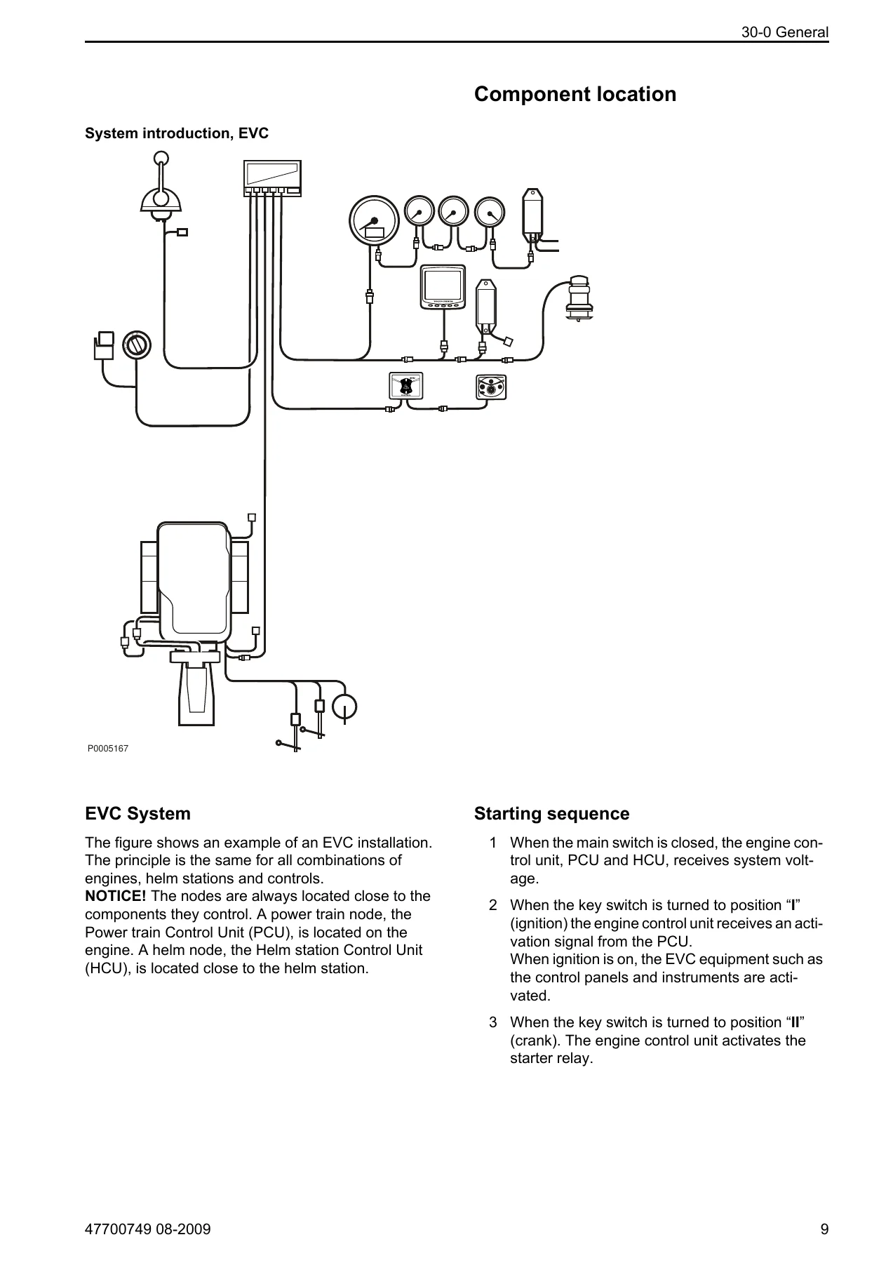
- System introduction, EVC
- Component location
- Starting sequence
- Transmission components
- PCU (Powertrain Control Unit)
- HCU (Helm station Control Unit)
- SCU (Steering Control Unit)
- SUS (Servo Unit Steering)
- CPM (Corrosion Protection Module)
- Identification of nodes
- Drive position sensor (DPH/DPS)
- Resolver
- Hydraulic valve plate
- Solenoid valves, Forwards-Reverse
- Solenoid valve, trolling
- Solenoid valves, transmission
- Interface bracket
- Lever Control
- Potentiometer
- Neutral switch
- Actuator (gas and diesel)
- General advice on working with EVC engines
- Repair Instructions
- Electric welding
- Fault tracing of cables and connectors
- Fault tracing the EVC system
- Check instruments
- Reprogramming a control unit
- Programming an empty control unit
- Malfunctions
- Fault code information (MID, PID, PPID, SID, PSID, FMI)
- FMI table
- 30-2 Fault Tracing
- Fault Codes
- MID 164 (HCU) fault codes: SID 226 Transmission neutral switch, SID 231 SAE J1939 data link, SID 240 Program memory, SID 250 SAE J1708/J1587 data link, SID 253 Calibration memory EEPROM, SID 254 Controller 1, PPID 29 Sport Fish Panel, PPID 289 Power trim control signal, PPID 390 Lever 1 position, PPID 391 Lever 2 position, PPID 392 Lever Potentiometer Supply, PPID 393 EVC Bus power input, PPID 394 Key supply, PPID 397 Main panel supply, PPID 424 Steering wheel position, PSID 63 External lever, PSID 64 Joystick, PSID 65 Joystick On button, PSID 66 Joystick High button, PSID 67 Joystick position divergence, PSID 68 Display, PSID 69 Menu Control Knob, PSID 74 Side Selection Button, PSID 75 Multi-function button, PSID 76 Back button, PSID 77 Sport Fish Mode button, PSID 78 Single Lever Control button, PSID 80 Multisensor, PSID 81 Lever Potentiometer, PSID 82 Helm station transfer function, PSID 83 Single lever control data component, PSID 92 Detection fault, PSID 94 Incompatible EVC software, PSID 95 Lever detection, PSID 96 Calibrated lever travel too small, PSID 97 Lever calibration procedure, PSID 98 Lever(s) not calibrated, PSID 99 EVC Bus network configuration fault, PSID 103 Neutral button, PSID 104 Lighting button, PSID 105 Active station button, PSID 106 Start switch, PSID 107 Stop switch, PSID 133 Steering wheel data link, PSID 134 Steering wheel module, PSID 135 Steering wheel brake, PSID 136 Steering wheel controller, PSID 137 Rudder angle, PSID 138 Steering position divergence, PSID 139 Autopilot, PSID 140 Incompatible helm station software, PSID 163 Data Link MID 200, PSID 209 Data link MID164, PSID 218 Data link 2 MID187, PSID 226 SAE J1939 Data Link Datalink2 MID164, PSID 231 Incompatible chassi id, PSID 232 SAE J1939-1 SubNet 1 Control link
- MID 187 (PCU) fault codes: PID 96 Fuel level, PID 127 Transmission oil pressure, PID 177 Gearbox oil temperature, PID 191 Output shaft speed, PPID 393 EVC Bus power input, PPID 398 Shift actuator position, PPID 399 Potentiometer supply shift actuator, PPID 400 Transmission sensor supply, PPID 401 Power trim position, PPID 402 Power trim potentiometer supply, PSID 10 Incompatible engine type, PSID 14 Detection fault, PSID 16 Incompatible EVC software, PSID 17 EVC Bus network configuration fault, PSID 18 EVC Bus Power Output E, PSID 19 EVC Bus Power Output C, PSID 20 Transm. primary solenoid, PSID 22 Transm. secondary solenoid, PSID 24 Gear actuator eng. direction 1, PSID 30 POWER TRIM Motor direction UP, PSID 31 POWER TRIM Motor direction DOWN, PSID 32 EVC Bus Communication with Active Helm Failure, PSID 107 Shift actuator potentiometer, PSID 163 Data link MID 200, PSID 200 Data Link MID128, PSID 226 SAE J1939 Data Link Datalink2 MID164, PSID 231 Incompatible chassi id, PSID 232 SAE J1939-1 SubNet 1 Control link, SID 231 SAE J1939 data link, SID 240 Program memory, SID 250 SAE J1708/J1587 data link, SID 253 Calibration memory EEPROM, SID 254 Controller 1
- MID 200 (CPM) fault codes: PPID 344 Active anode potential, PPID 345 Passive anode potential, PPID 444 Polarization potential, PPID 447 Polarization current, SID 231 SAE J1939 data link, SID 240 Program memory, SID 253 Calibration memory EEPROM, SID 254 Controller 1
- MID 250 (SUS) fault codes: PID 168 Battery potential, PPID 55 ECU temperature, PPID 393 EVC Bus power input, PPID 424 Steering wheel position, PPID 426 Rudder angle, PPID 427 Servo motor temperature, PSID 1 EVC bus network config, PSID 2 EVC bus power output C, PSID 3 Servo motor, PSID 4 Rudder brake, PSID 6 EVC Bus Communication, PSID 9 Steering Control Unit and steering sensors, PSID 10 Steering Control Unit, PSID 92 Detection fault, PSID 209 Datalink MID164, PSID 232 SAE J1939-1 SubNet 1 Control link, SID 231 SAE J1939 data link, SID 240 Program memory, SID 253 Calibration memory EEPROM, SID 254 Controller 1
- MID 250 (SCU) fault codes: PID 168 Battery potential, PPID 393 EVC Bus power input, PPID 424 Steering wheel position, PPID 426 Rudder angle, PPID 1156 Hydraulic oil temp, PPID 1559 Steering solenoid STBD, PPID 1560 Steering solenoid PORT, PPID 1561 Steering solenoid (service valve), PPID 1670 Steering sensor (DPS top DPH port), PPID 1671 Steering sensor (DPS bottom DPH starboard), PPID 1677 EVC bus power input (C), PSID 1 EVC bus network config, PSID 2 EVC bus power output C, PSID 5 Incompatible EVC software, PSID 6 EVC Bus Communication, PSID 9 Steering Control Unit and steering sensors, PSID 10 Steering Control Unit, PSID 92 Detection fault, PSID 231 Incompatible chassi id, PSID 232 SAE J1939-1 SubNet 1 Control link, SID 240 Program memory, SID 253 Calibration memory EEPROM, SID 254 Controller 1
- 37-0 Wiring Diagrams
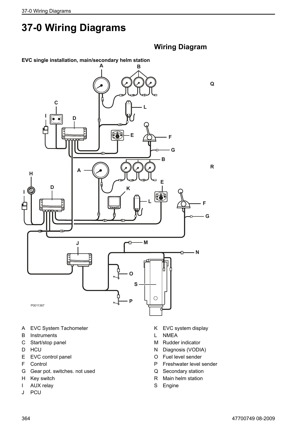
- EVC single installation, main/secondary helm station
- Wiring diagram for electronic steering
- Schematic of the hydraulic valve plate
- D4/D6 wiring diagrams
- EMS wiring diagrams
- Pin configuration, PCU
- Pin configuration, HCU
- Pin configuration, SUS
- Pin configuration, CPM
- Pin configuration, SCU
- Break out cable 88890016 pin configuration
- 39-0 General
- Alphabetical index
- References to Service Bulletins
What This Manual Gives You
The Volvo Penta EVC-C3 Workshop Manual for Group 30 Electrical System is a complete diagnostic and repair resource for the electronic control network used on D3-D16 diesel and gas engines. It begins with the design and function of the EVC system, explaining how the distributed nodes — PCU, HCU, SUS, SCU, and CPM — communicate over CAN bus and J1587 networks. From there, it provides exhaustive fault tracing procedures organised by MID (Message Identification Description), with every fault code broken down into FMI (Failure Mode Identifier), symptoms, possible causes, and suitable actions.
Each fault code entry includes the conditions that trigger the code, the components involved, and the exact measurement procedures required to verify the fault. Wiring descriptions and connector pinouts are provided for every node, so you can trace signals from sensor to control unit with confidence. The manual also covers calibration procedures, software programming, auto configuration, and node replacement — all critical tasks when servicing an EVC-equipped vessel.
The wiring diagram section provides complete system schematics for single installations, electronic steering, hydraulic valve plates, and engine-specific configurations for D4/D6 and EMS engines. Pin configurations for every connector are listed, along with the break-out cable numbering needed when using Volvo Penta special tools. This is the manual that Volvo Penta workshops use to diagnose and repair the EVC-C3 electrical system, and it is now available as an instant PDF download.
Who This Manual Is For
This workshop manual is written for Volvo Penta technicians, marine engineers, and experienced boat owners who need to service, diagnose, or repair the EVC-C3 electrical system on D3-D16 diesel and gas engines. It assumes a fundamental knowledge of the product and the ability to carry out mechanical and electrical work to trade standard. The procedures reference Volvo Penta special tools such as the VODIA diagnostic tool (3838619), the break-out box (9998699), and the multimeter (9812519), so having access to these tools will allow you to follow the fault tracing steps precisely.
If you are working on a vessel equipped with EVC-C3, this manual gives you the fault code definitions, measurement values, connector pinouts, and repair instructions needed to resolve electrical faults correctly. It covers everything from a simple neutral switch fault to complex CAN bus communication errors, steering system failures, and corrosion protection module diagnostics.
Why This Manual Matters
Electrical faults in a marine EVC system can be difficult to diagnose without the correct reference data. A fault code alone does not tell you which wire to check, what resistance value to expect, or which component to replace. This manual bridges that gap by providing the exact measurement points, nominal values, and logical action steps for every fault code in the system.
Because the EVC system uses a distributed network, a fault in one node can produce symptoms in another. The fault tracing sections explain how to isolate the problem, check the wiring between nodes, and verify the function of each component. The wiring diagrams show the complete system layout, so you can see how power, CAN bus signals, and sensor data flow through the vessel. This level of detail reduces diagnostic time, prevents unnecessary parts replacement, and helps ensure the repair is done correctly the first time.
IMAGES PREVIEW
Instant PDF Delivery
This Volvo Penta EVC-C3 Workshop Manual is delivered as an instant PDF download. There is no shipping, no waiting for a physical book, and no restrictions on how you use it. You can view it on any device — laptop, tablet, or smartphone — and print the pages you need for the workshop. Whether you are at the dock, in the engine room, or at the bench, you have the full manual at your fingertips. The PDF format allows you to search for fault codes, print specific procedures, and keep the entire electrical system reference with you wherever you work.


Reviews
There are no reviews yet.