
Volvo Penta EVC-E Group 30 Electrical System Workshop Manual 2022
Original price was: $44.95.$27.95Current price is: $27.95.
Complete Volvo Penta workshop manual for the EVC-E electrical system (Group 30) – fault codes, fault tracing, VODIA log parameters, measurements, circuit descriptions and full wiring diagrams. Doc 47703793, 2022 edition, English, PDF.
Description
Volvo Penta EVC-E Group 30 Electrical System Workshop Manual
This is the full Volvo Penta workshop manual covering Group 30 – Electrical System for the EVC-E (Electronic Vessel Control) platform. At roughly 450 pages it is the deepest single reference available for diagnosing, measuring and repairing the EVC-E electrical network on Volvo Penta marine installations, from the first connector check to a full node replacement.
File Details
- Manual type: Workshop Manual (Service Manual)
- Brand: Volvo Penta
- Group: 30 – Electrical System
- System: EVC-E (Electronic Vessel Control)
- Document number: 47703793
- Edition / date: 09-2022 (earlier printing 06-2019)
- Language: English
- Page count: approx. 450 pages
- File format: PDF
Chapters Covered
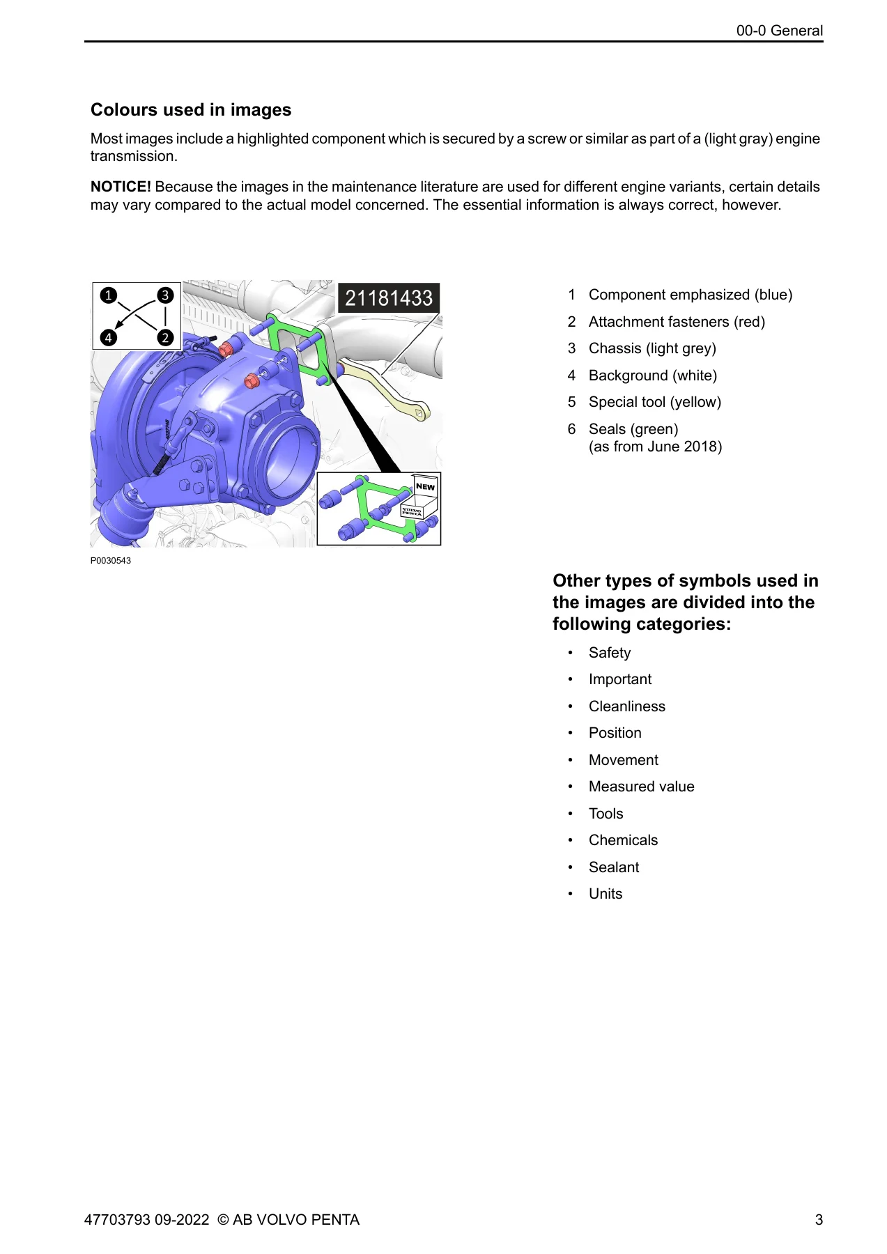
- General Information 00-0 – general, replacement parts, certified engines, colours and symbols used in images, safety information
- Special Service Tools 08-2 – special service tools, break-out cables, break-out box, VODIA, multimeter, mounting tool, crank tool, brake release switch
- General, Complete Vehicle Software 30-0 – EVC system design and function, node identification, repair instructions, malfunctions, abbreviations, electrical welding, Volvo Penta Glass Cockpit service and support
- Fault Tracing 30-2 – General fault tracing, fault tracing of cables and connectors, EKS system fault tracing, DTC categories, fault codes
- Fault Codes 30-2 – full MID / PID / PPID / SID / PSID / FMI fault code tables for HCU, PCU, MGX, BCM, ICM, STCM, CPM, SUS and SCU
- Measurements 30-2 – EVC bus, multilink bus, aux bus, DPS gateway, steering control bus, diesel key switch diode, sensors, solenoids, resolvers and actuator measurements
- VODIA Log Parameters 30-2 – HCU, PCU, CPM and SCU log parameters with working ranges and normal values
- Circuit / Component Descriptions 30-2 – EVC bus, A-CAN, hydraulic oil temperature sensor, steering solenoids, service valve, multilink hub, drive position sensors, key panel / LIN bus, steering control bus, fuel level, multilink bus, aux bus, transmission oil and temperature, slip, PCU-EECU wiring, gear shift actuator, gear shift solenoids, powertrim, CWES, DPS gateway, joystick, NMEA, VP autopilot connection, CPM
- Cables and fuses 37-0 – pin configuration for PCU, HCU, SUS, CPM, SCU and STCM, plus all wiring diagrams
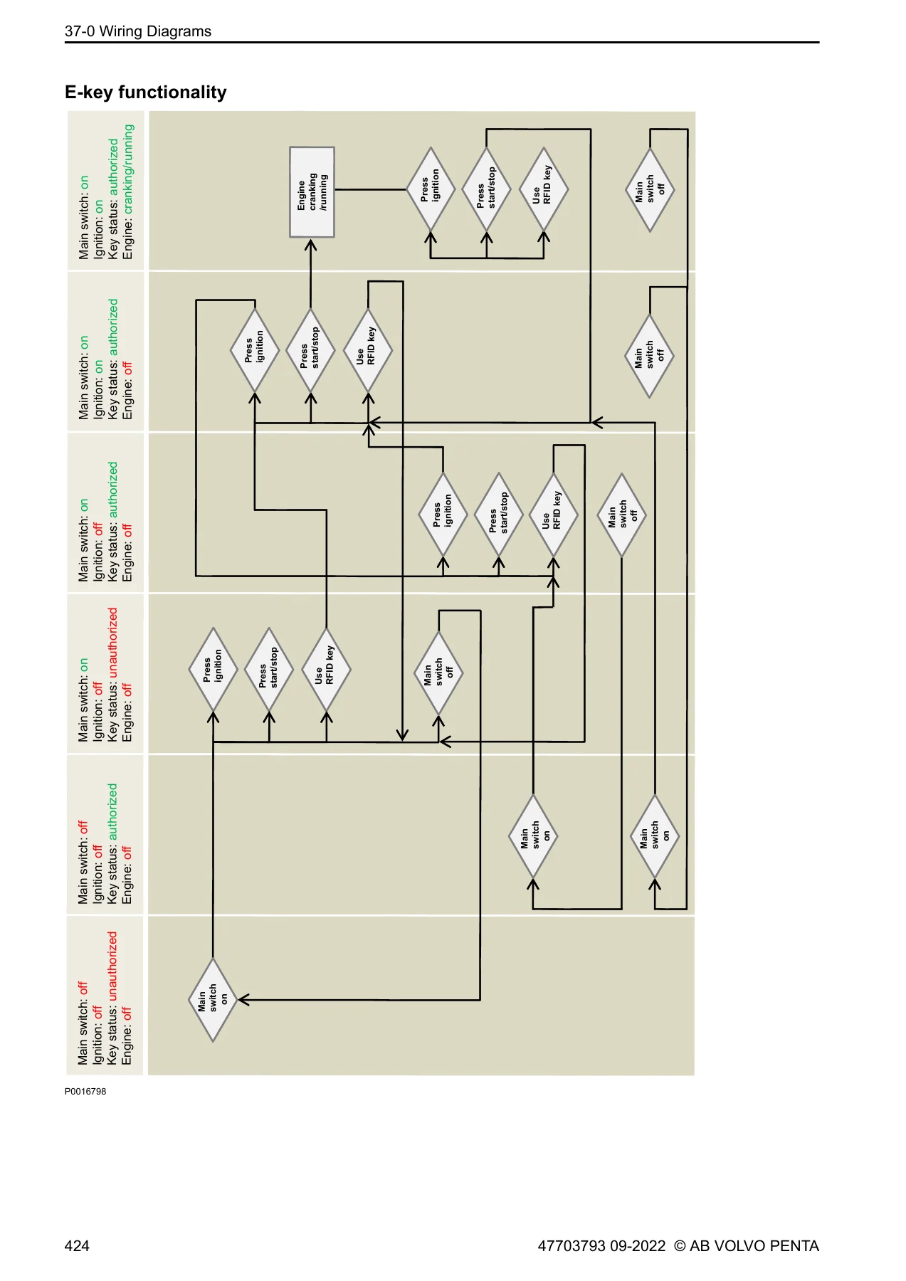
- Wiring Diagrams 37-0 – electronic steering, hydraulic valve plate schematic, multilink T-split and hub, aux bus Y-splits, e-key harnesses, 4-20 mA interface, PCU outputs for AQ drive D3, AQ drive D4/D6, IPS1, IPS2/IPS3, D8, HS rev. gear, ZF rev. gear and MGX rev. gear
- Miscellaneous 39-0 – complete index
- References to Service Bulletins
Across those chapters the manual builds a full diagnostic workflow rather than a list of parts. You start with safety information and special tools, move into the distributed EVC-E node architecture (PCU, HCU, SUS and SCU), then work through fault tracing logic, the complete FMI / MID / PSID / PPID / SID fault code library, and finally the measurement procedures and pin-level wiring diagrams that let you confirm the fault with a multimeter before you touch a component.
Systems and Components Covered
The fault code and circuit sections cover the EVC bus (125 kbit/s, powered from the PCU over X2), the multilink bus (250 kbit/s with display and panel power), the aux bus (250 kbit/s, always terminated), the steering control bus (125 kbit/s) and the LIN bus used by the key panel. Component-level coverage extends to the HCU lever unit, joystick, steering wheel unit, drive position sensors, steering and service solenoids, the resolver, powertrim potentiometer and relays, gear shift actuator and shift solenoids, slip solenoid, propeller shaft speed sensor, transmission oil pressure and temperature sensor, oil quality sensor, clear wake exhaust valve, CPM active corrosion protection, BCM battery management, ICM interceptor servo modules, STCM thruster control and the DPS gateway.
Fault Code Depth
Every fault code entry is written in a consistent structure: DTC category, fault code explanation, fault indication (red or yellow alarm status), whether it is stored in memory, symptom list, conditions for the fault code with time limits, possible reasons and suitable actions, followed by logging parameters and the measurement page to use. That structure means you can go straight from a code on the display to the exact wire, pin and voltage you need to check, instead of guessing at the component.
Wiring Diagrams and Pin Data
The wiring section gives complete pin configurations for the PCU, HCU, SUS, CPM, SCU and STCM connectors, then full schematics for each driveline variant. Coverage includes AQ drive D3, AQ drive D4/D6, D8, IPS1, IPS2/IPS3 with D11/D13, HS reversing gear D3/D4/D6, ZF reversing gear D11/D13 and MGX reversing gear D13, plus the electronic steering diagram and the hydraulic valve plate schematic. If you are chasing a chafed loom or a swapped connector, this is the section that settles it.
What This Volvo Penta EVC-E Group 30 Electrical System Workshop Manual Enables You To Do
With this manual on hand you can read and interpret an EVC-E fault code correctly, carry out the fault tracing sequence the manufacturer expects before condemning a sensor, measure the EVC bus, multilink bus, aux bus and steering control bus at the correct pins with the correct expected values, test steering and service solenoids, the resolver, drive position sensors, the powertrim potentiometer and the gear shift actuator potentiometer, verify CPM active corrosion protection signals, check the DPS gateway and autopilot gateway LED states, perform auto configuration and calibration routines, and reprogram or replace an HCU, PCU, SUS, SCU, STCM, ICM or CPM in the right order.
The value is in the procedure. Electrical faults in a networked EVC-E installation rarely fail in the component they appear to – they fail in a connector, a shared power supply or a bus segment. This Volvo Penta EVC-E Group 30 Electrical System Workshop Manual gives you the fault code conditions, the time limits the node uses to set a code, the nominal voltages and resistances, and the wiring diagrams together, so you diagnose the actual cause instead of replacing parts until the alarm clears.
Delivery
IMAGES PREVIEW
The file is delivered as an instant PDF download after payment – no shipping, no waiting for a parcel. It opens on any laptop, tablet or phone, and you can print the fault code pages, measurement pages or a wiring diagram and take them out to the boat. Keep it on a workshop tablet and you have the entire EVC-E electrical system reference in one searchable-sized document, ready the next time an alarm appears on the display.
Reviews
There are no reviews yet.