

Wärtsilä 31DF Series Product Manual 2019 – 8V, 10V, 12V, 14V & 16V31DF Dual Fuel Engine Guide PDF
Original price was: $59.95.$39.95Current price is: $39.95.
Complete 221-page Wärtsilä 31DF Series Product Manual for the 8V, 10V, 12V, 14V and 16V31DF dual-fuel marine engines — outputs, technical data, fuel gas and fuel oil systems, cooling water, exhaust, automation and installation planning data. Instant PDF download.
Description
Wärtsilä 31DF Series Product Manual — 2019 Edition
The Wärtsilä 31DF Series Product Manual is the complete product guide for the Wärtsilä 31DF dual-fuel marine engine range, covering the 8V31DF, 10V31DF, 12V31DF, 14V31DF and 16V31DF configurations. This 221-page manual is written for the early design phase of marine engine installations — the stage where engine selection, auxiliary system sizing, piping layout, cooling water circuits, fuel gas supply, exhaust design and automation interfaces are all locked in. It is the working document naval architects, marine engineers and shipyard project teams rely on before the project-specific installation planning instructions are issued.
File Details
- Manual type: Product Guide / Installation Planning Manual
- Brand: Wärtsilä
- Model range: 31DF Series — W8V31DF, W10V31DF, W12V31DF, W14V31DF, W16V31DF
- Engine type: 4-stroke, non-reversible, turbocharged and intercooled dual-fuel (DF) engine with direct fuel injection
- Language: English
- Page count: 221
- File format: PDF
- Edition: Issue 01/2019, March 2019, Vaasa
- Copyright: © 2019 Wärtsilä Finland Oy
Chapters Covered
- 1. Main Data and Outputs
- 2. Operating Ranges
- 3. Technical Data
- 4. Description of the Engine
- 5. Piping Design, Treatment and Installation
- 6. Fuel Oil System
- 7. Lubricating Oil System
- 8. Compressed Air System
- 9. Cooling Water System
- 10. Combustion Air System
- 11. Exhaust Gas System
- 12. Turbocharger Cleaning
- 13. Exhaust Emissions
- 14. Automation System
- 15. Foundation
- 16. Vibration and Noise
- 17. Power Transmission
- 18. Engine Room Layout
- 19. Transport Dimensions and Weights
- 20. Product Guide Attachments
- 21. ANNEX
Main Data, Outputs and Operating Ranges
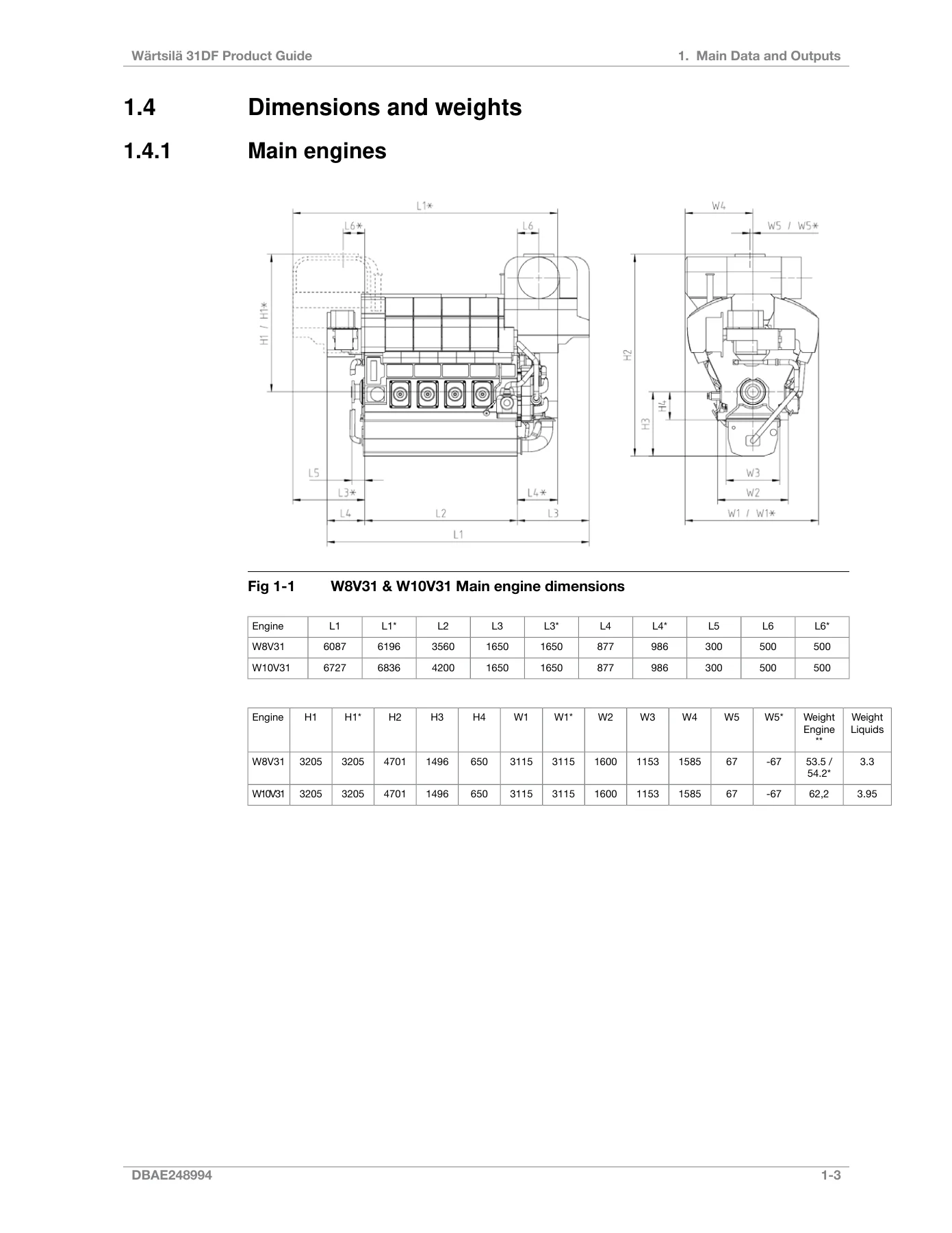
Chapter 1 opens with the engine’s fundamental architecture: 310 mm cylinder bore, 430 mm piston stroke, a 50° V-angle, two inlet and two exhaust valves per cylinder, and a rated speed of 720 or 750 rpm. The maximum continuous output table lists the rating for every cylinder configuration in main engine and generating set duty, and the mean effective pressure formula is printed for verification work. Reference conditions, permissible inclination angles for Marine Solutions engines, and full principal dimensions and dry/wet weights for the 8V, 10V, 12V, 14V and 16V blocks are tabulated alongside dimensioned outline drawings. Chapter 2 then covers the engine operating range — the load-versus-speed envelope for controllable pitch propeller (CPP), diesel-electric and auxiliary engine duty, loading and unloading ramps for variable-speed and constant-speed installations, instant load application limits, low-load operating restrictions in both gas and diesel modes, and minimum inlet air temperatures in gas and diesel mode.
Technical Data
Chapter 3 is the largest single reference block in the Wärtsilä 31DF product guide. Each of the five cylinder configurations has its own data set covering combustion air flow, exhaust gas flow and temperature at 100%, 85%, 75% and 50% load, heat balance figures for the HT jacket water circuit, HT and LT charge air circuits and the lubricating oil circuit, radiation losses, total energy and fuel gas consumption in both gas and diesel modes, fuel gas and fuel oil system pressures, lubricating oil system pressures and pump capacities, cooling water system pressures, capacities and pressure drops, and starting air system pressure and consumption. Engine-driven pump correction tables and the notes governing tolerance, fouling factors and ISO 15550 validity are printed alongside the data.
Description of the Engine
Chapter 4 walks through the mechanical design of the 31DF — from the nodular cast iron engine block and underslung crankshaft through the three-piece connecting rod, tri-metal main and big end bearings, centrifugal cast cylinder liners, composite pistons and hydraulic valve actuation. The two-stage turbocharging and charge air cooling arrangement, electronic fuel injection equipment, gas admission valves, micro-pilot ignition concept, integrated lubricating oil module and split HT/LT fresh water cooling circuits are all described. The chapter closes with recommended times between inspection or overhaul and expected component life for MDF/gas and HFO operation, plus engine storage guidance.
Piping, Fuel and Lubricating Oil Systems
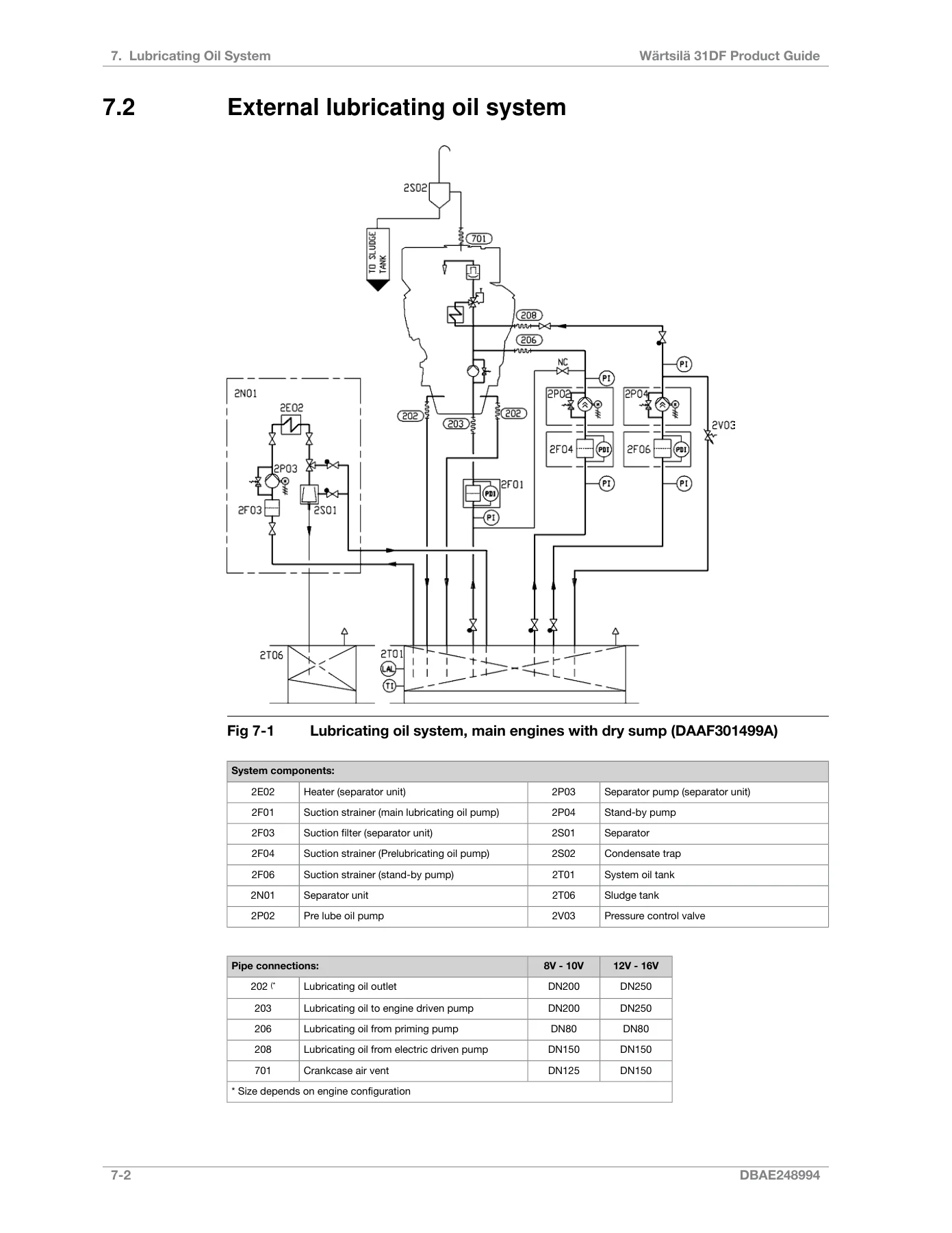
Chapter 5 sets out the general design, treatment and installation rules for the engine pipework — material selection, recommended maximum flow velocities for LNG, fuel gas, MDF/HFO, lubricating oil, fresh water and sea water piping, trace heating requirements, pressure and pipe classes, insulation, cleaning and pickling procedures, and the correct installation and clamping of flexible pipe connections. Chapter 6 covers the fuel oil system in depth, including acceptable gas fuel characteristics (methane number, methane content, hydrogen sulphide, oil content, ammonia, particulates) and the full ISO 8217:2017(E) liquid fuel specification for DMX, DMA, DFA, DMZ, DFZ, DMB and DFB distillates as well as RMA 10, RMB 30, RMD 80, HFO 1, HFO 2 and crude oil operation. The external fuel gas system with open or enclosed gas valve unit (GVU), double-wall gas piping ventilation, master fuel gas valve, inert gas purging, gas feed pressure requirements and GVU P&I diagrams are all included. The external fuel oil system schematics for MDF and HFO installations — single and multiple engine — appear with component keys, feeder/booster unit design data, separator sizing, heater capacity calculations and flushing procedures. Chapter 7 sets out lubricating oil requirements by fuel grade, the external lubricating oil system for dry and wet sump engines, separation system sizing, system oil tank design, suction strainers, pre-lubricating oil pump, pressure control valve, stand-by pump and the crankcase ventilation system.
Compressed Air, Cooling Water and Combustion Air
Chapter 8 covers instrument air quality and the external compressed air system, including starting air compressor units, oil and water separators, starting air vessel sizing and the formula for required total vessel volume. Chapter 9 deals with cooling water — water quality limits for pH, hardness, chlorides and sulphates, corrosion inhibitor requirements, glycol restrictions, the split HT/LT circuit layout, arctic-condition cooling, stand-by circulation pumps, sea water pumps, temperature control valves, central cooler, waste heat recovery, air venting, expansion tank design and HT preheating calculations. Chapter 10 addresses engine room ventilation and combustion air system design, including air flow calculation, combustion air fans, duct sizing and the optional charge air shut-off valve.
Exhaust, Emissions and Turbocharger Cleaning
Chapter 11 covers the exhaust gas outlet and external exhaust system — pipe diameters and supports by engine size, flexible bellows, system design for explosion safety in gas operation, exhaust gas ventilation unit, rupture discs, back pressure limits, exhaust gas boiler and SCR unit arrangement, and silencer selection (conventional and Compact Silencer System). Chapter 12 covers the turbocharger turbine and compressor water washing system with its dosing unit and water supply requirements. Chapter 13 summarises dual-fuel engine exhaust components and IMO / MARPOL Annex VI emission legislation.
Automation, Foundation and Layout
Chapter 14 describes the Wärtsilä Unified Controls (UNIC) automation system — architecture, ingress protection, power unit, communication modules, cylinder control modules, engine safety module, local operator panel, start blocking and start sequences, gas/diesel transfer control, stop, shutdown and emergency stop modes, speed control for main engines and generating sets, alarm and monitoring, electrical consumers and diesel-electric propulsion system requirements. Chapter 15 covers foundation design — steel structure, rigid mounting on steel or resin chocks, resilient mounting, and mounting of generating sets on rubber elements. Chapter 16 gives external forces and couples, mass moments of inertia, airborne noise and exhaust noise data. Chapter 17 covers power transmission: flexible coupling, torque flange, clutch, shaft locking device, turning gear and the input data needed for torsional vibration calculations. Chapter 18 provides crankshaft distances and service and maintenance space requirements. Chapter 19 gives transport dimensions, weights and lifting arrangements, and Chapter 21 contains unit conversion tables plus a collection of drawing symbols.
Why This Wärtsilä 31DF Product Manual Matters
The Wärtsilä 31DF is a modern dual-fuel marine engine, and getting the installation planning right the first time is the difference between a smooth commissioning and months of re-work. This product guide puts the engine outputs, heat balance, flows, pressures, system schematics and automation signal interfaces in one place, so auxiliary systems, piping, cooling circuits, fuel gas supply and the exhaust arrangement can be sized and specified against the manufacturer’s own figures rather than rough estimates. Whether you are specifying a newbuilding, retrofitting a 31DF into an existing engine room, or supporting an operating vessel, this manual gives you the reference data the design team and the classification society will ask for.
IMAGES PREVIEW
Delivered as an instant PDF download, the manual is fully printable and can be opened on a laptop, tablet or phone. No shipping, no waiting — buy, download, and the Wärtsilä 31DF Series Product Manual is in your hands the same minute.
Reviews
There are no reviews yet.