
Acuson 128XP Computed Sonography Systems Service Manual PDF
Original price was: $39.95.$24.95Current price is: $24.95.
Download the Acuson 128XP Computed Sonography Systems Service Manual PDF, covering service, troubleshooting, scanner, scan converter, power supply, maintenance, and performance verification for 128XP/10, 128XP/5, 128XP/E, 128/10, and 128/5 systems.
Description
Acuson 128XP Computed Sonography Systems Service Manual PDF
The Acuson 128XP Computed Sonography Systems Service Manual PDF is a technical service reference for the Acuson 128XP family of computed sonography systems. It is written for service personnel who maintain, troubleshoot, and verify these systems, and it addresses the 128XP/10, 128XP/5, 128XP/E, 128/10, and 128/5 configurations. The manual is organized around the major functional groups of the system: the Scanner, Scan Converter, and Power Supplies, with additional sections for preventative maintenance, performance verification, parts lists, and engineering drawings. This is a service manual rather than an operator tutorial; it assumes familiarity with basic test equipment, ultrasound theory, and the architecture of the Acuson 128XP.
File Details
- Manual type: Service Manual
- Brand: Acuson
- Model: 128XP Computed Sonography Systems
- Covered systems: Acuson 128XP/10, 128XP/5, 128XP/E, 128/10, and 128/5
- Language: English
- File format: PDF
- Edition: First Edition, January 1991
- Page count: 370 pages in the supplied PDF
What the Manual Covers
The scope statement explains that this manual should be used when servicing all Acuson 128XP/10, 128XP/5, 128XP/E, 128/10, and 128/5 systems. It notes that systems referred to as Acuson 128/10 or 128/5 have been upgraded to XP capabilities in the field, and that their operation and circuit boards are covered in this manual. The Acuson 128XP/E was designed to emulate the Acuson 128 system, and while its chassis is identical to the XP/10 and XP/5, it operates at a different software revision level and does not support XP capabilities unless an XP upgrade is performed in the field. This is important context for anyone using the Acuson 128XP service manual across mixed system configurations.
The document is arranged in sections corresponding to the major functional groups within the Acuson 128XP. Each section provides information about the overall architecture, troubleshooting techniques, and details about the subassemblies pertinent to that functional group. The manual also contains routine maintenance information and reference materials, including parts lists and engineering drawings. It is a practical reference for on-site service and repair, where the design is based on modular, functionally isolated printed circuit boards and subassemblies that simplify service and repair.
Chapters Covered
- 1. Introduction – Preface, scope of manual, PCB type, version and revision identification, safety precautions, required facilities, environmental requirements, electrical requirements, transducer care, handling transducers, inspecting transducers, system care, cleaning and sanitizing the cabinet, and air filter care and cleaning.
- 2. System Overview – Ultrasound basics, system architecture, system troubleshooting, power-up errors, performance problems, and system switch configurations.
- 3. Scanner – Scanner architecture, scanner operation, scanner chassis, scanner subsystems, scanner troubleshooting, power-up errors, operational problems, and scanner assemblies including APD, AUX, BBQ, DBL, DBR, DCC, IGD, MEX, MXK, RCV, SCP, SDL, SGD, SGI, SMB, STG, TDI, TRM, VDT, XDY, and XMT boards.
- 4. Scan Converter – Scan Converter architecture, 2-D operation, spectral Doppler operation, color Doppler operation, cardiac M-mode operation, cine operation, physio interface signal processing, scan converter troubleshooting, power-up errors, operational problems, and scan converter assemblies including AUD, CED, CMB, CSC, CSI, CVC, DAQ, DCP, DSP, ECG and Physio, FEB, FEC, FPC, IC, MMB, OC, PEM, SCM, SCMB, SI, and VC boards.
- 5. Power Supply – Power supply architecture, theory of operation, power supply subassemblies, PDB 2, FDB, PPS, scanner analog power supply, scanner digital power supply, scan converter power supply, troubleshooting the power supply, common failure modes and causes, and specifications including AC power consumption, frequency tolerance, line voltage, and temperature tolerance.
- 6. Preventative Maintenance – Preventative maintenance checklist, preliminaries, mechanical and visual inspection, electrical checks, and transducer check.
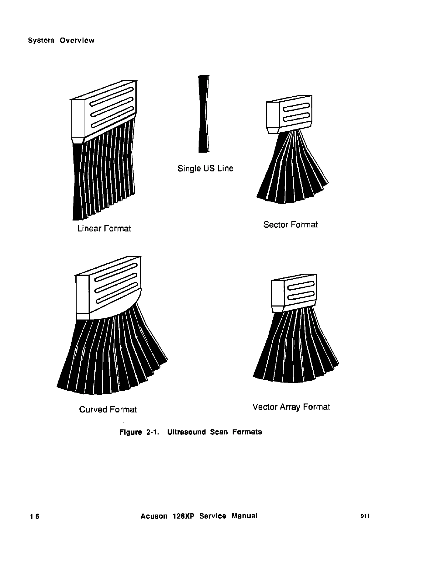
- 7. Performance Verification – Operational tests, sector, linear, curved, and Vector Array formats, system and monitor controls, primary controls, secondary controls, customizing controls, pulsed Doppler performance check, color Doppler performance check, sector and Vector Array color, auxiliary CW Doppler performance check, M-mode performance check, ECG and Physio module performance check, and OEM peripheral performance checks.
- 8. Parts Lists – Cables and wire harnesses, cable assemblies, flat ribbon, high speed coax, fans, air filters, foam and rubber, electrical hardware, mechanical hardware, labels, manuals and video tapes, monitors, OEM devices and accessories, metal parts, plastic parts, power supplies, assemblies, circuit breakers, components and assemblies, fuses, printed circuit boards, switch assemblies and switches, transducers, accessories, user controls, keyboards and keycaps, and knobs.
- 9. Engineering Drawings – Upper cart assembly, scan converter assembly, monitor bezel assemblies, keyboard and trim assemblies, lighted switch board assembly, soft key switch board assembly, I/O panel assembly, upper cart power supply, scanner chassis assembly, baffle and fan driver board assembly, power supply tray sheets, rear panel sheets, AC power distribution, and DC power distribution pages.
- 10. Glossary
- 11. Index
Across these sections, the manual gives a technician a structured path through the system rather than a collection of unrelated tips. It starts with safety, facilities, and care information, then moves into the system architecture and switch configurations before breaking the hardware down into the Scanner, Scan Converter, and Power Supply groups. The troubleshooting sections are written around systematic replacement of subassemblies, and the manual explains how to reduce the number of assemblies replaced while locating a fault. For each major board and subassembly, the text provides function, revision requirements, and troubleshooting information where applicable.
Service and Troubleshooting Coverage
The Acuson 128XP Computed Sonography Systems Service Manual PDF gives service personnel a detailed view of the Scanner and Scan Converter board sets. The Scanner section covers the hybrid analog and digital computer that controls timing, phase, and amplitude for each of the 128 channels. It explains the Scanner set-up, transmission, and reception cycles, and it describes the role of boards such as the Receiver, Transmitter, Summing Delay Line, Apodizer, Mixer Clock, Transmit Delay, Scanner Control Processor, Dual Channel Controller, Scanner Timing Generator, Memory Expansion, Distribution Board Right, Distribution Board Left, Interpolating Gain Driver, Scanner Gain Driver, Scanner Gain Interpolator, Video Detector, and Transducer Interconnect. The troubleshooting content includes power-up error messages such as S.INTRPT Power-up Error, DPR Power-up Error, SCP Power-up Error, DCC Power-up Error, MEMEX Power-up Error, Power Supply Failure, Scanner and Microcode Incompatible, Scanner Timing Generator Problem, Obsolete DCC Boards, and Scanner Orphan Prom Not Present.
The Scan Converter section explains the conversion of ultrasound scan formats to video raster format and covers 2-D imaging, spectral Doppler, color Doppler, cardiac M-mode, cine, and physio interface signal processing. It describes the roles of the Input Controller, Main Memory Board, Output Controller, Common Video Controller, Front Panel Controller, Doppler Acquisition Board, Doppler Spectral Processor, Display Control Processor, Audio Processor, Flow Estimator Calculator, Flow Estimator Buffer, Color Scan Converter, Color Encoder and Decoder, Cine Memory Board, Strip Chart and M-mode Board, Scan Converter Motherboard, System Interconnect, and Common System Interconnect. The troubleshooting tables list power-up messages and potential causes, which helps a technician decide which related boards to check rather than replacing only the board named in the message.
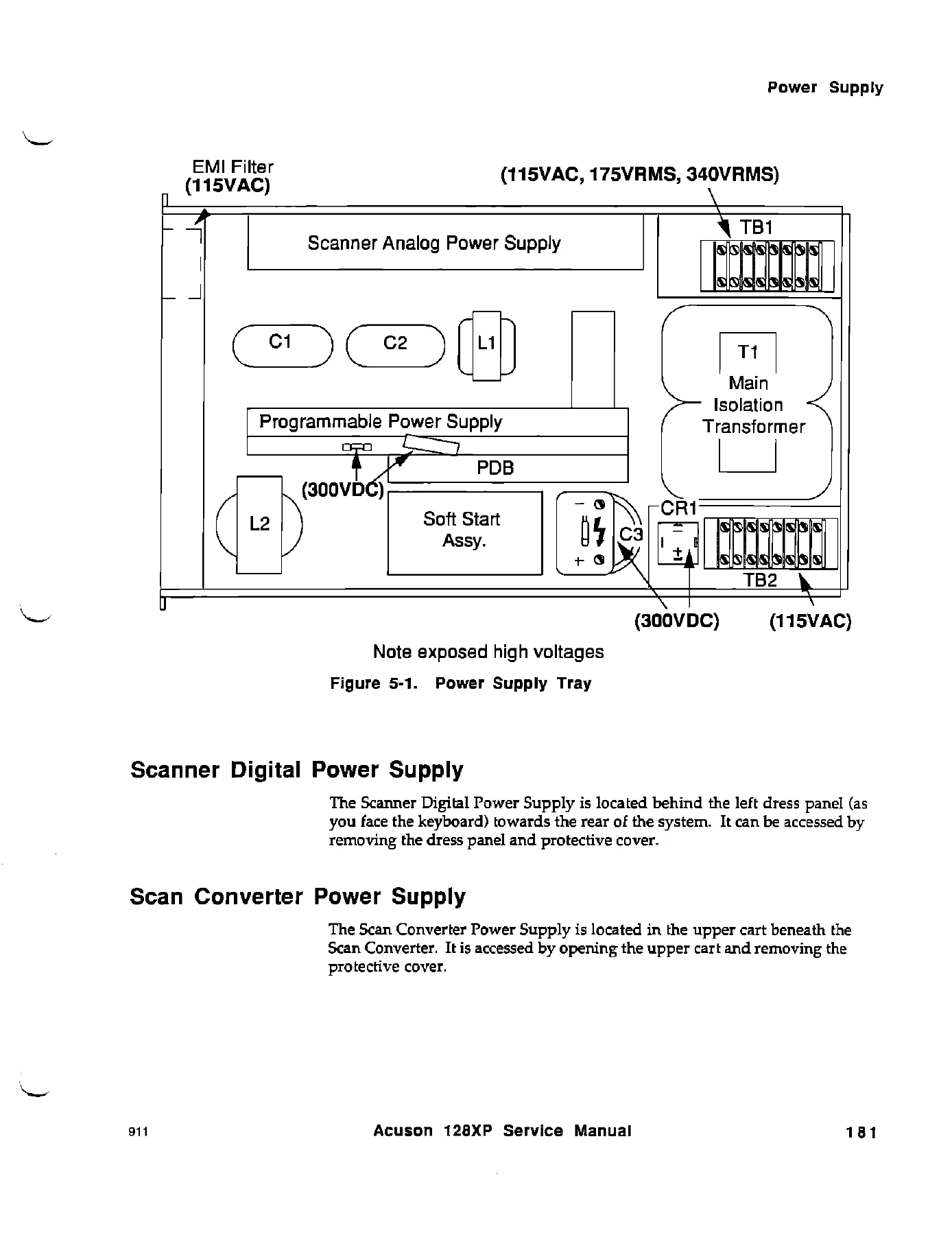
The Power Supply section covers the domestic and international power supply versions, the power supply tray, Scanner Digital Power Supply, and Scan Converter Power Supply. It explains AC power conditioning, primary AC wiring, soft-start, secondary AC wiring, voltage strapping, the 300 VDC bus, power factor correction, the power fail signal, PERCLK, power-on sequence, power-off sequence, and power supply noise. It also covers subassemblies including the Power Distribution Board 2, Fan Driver Board, Programmable Power Supply, Scanner Analog Power Supply, Scanner Digital Power Supply, and Scan Converter Power Supply, with troubleshooting and common failure modes. The manual includes important safety warnings about lethal voltages, high-voltage areas, and leakage current measurement after service activity on the primary side of the main isolation transformer.
Who This Manual Is For
This manual is intended for service personnel who are familiar with the use of basic test equipment such as an oscilloscope and DVM, basic ultrasound theory, and the architecture and theory of operation of the Acuson 128XP. It is not a first-time operator guide. It is a bench and field service reference for technicians who need to identify boards, understand signal flow, interpret power-up errors, perform preventative maintenance, and run performance verification checks. The section on transducer care and the section on system care are also useful for anyone responsible for the daily upkeep of the system, including air filter cleaning, cabinet cleaning and sanitizing, and proper handling and inspection of transducers.
What This Acuson 128XP Service Manual Delivers
With the Acuson 128XP Computed Sonography Systems Service Manual PDF, a service technician can work through system-level and board-level faults on the Scanner, Scan Converter, and Power Supplies with the manual’s architecture descriptions, troubleshooting tables, board functions, revision requirements, and performance verification procedures. The manual supports maintenance planning, power-up error diagnosis, signal-flow tracing, subassembly replacement decisions, preventative maintenance checks, and operational performance tests. Having the correct procedures and specifications matters because these systems contain high voltages, sensitive ultrasound signal paths, and modular boards that must be matched to the right revision level. The PDF is delivered instantly after payment, requires no shipping, can be viewed on any device, and can be printed for use in the service area.
IMAGES PREVIEW
Reviews
There are no reviews yet.