★ TRUSTED BY 321,897+ PROFESSIONALS WORLDWIDE
🏢
Trusted Business
Verified & Licensed
🛡️
Virus Free Files
100% Safe Downloads
🔒
Secure Payment
SSL Protected
Instant Delivery
Available Immediately
Sale!

Agusta A109E Rotorcraft Flight Manual with Supplements – PW206C PDF

Original price was: $44.95.Current price is: $26.95.

1021-page Agusta A109E Rotorcraft Flight Manual covering PW206C-powered A109E limitations, normal and emergency procedures, performance, weight and balance, systems, handling, optional-equipment appendices and supplements.

Instant PDF Download
Available immediately
💾
Save to Your Device
Download & keep forever
🛡️
Antivirus Scanned
100% virus-free
🌍
Trusted Worldwide
175,000+ customers

Description

Agusta A109E Rotorcraft Flight Manual with Supplements – PW206C PDF

The Agusta A109E Rotorcraft Flight Manual with Supplements – PW206C PDF is a comprehensive operating reference for the A109E helicopter, covering approved limitations and procedures together with manufacturer data, performance information, system descriptions, weight and balance material, handling guidance, optional-equipment appendices, and dedicated supplements. The manual identifies the A109E as powered by two Pratt & Whitney Canada PW206C turboshaft engines and combines the core Rotorcraft Flight Manual with a substantial body of configuration-specific material.

File Details

  • Manual type: Rotorcraft Flight Manual with optional-equipment appendices and supplements
  • Brand / model: Agusta A109E
  • Engine: Two Pratt & Whitney Canada Inc. PW206C turboshaft engines
  • Language: English
  • Page count: 1021 pages
  • File format: PDF
  • Issue date: 30th July 1997
  • Revision record: Front matter records revisions through Rev. 36

Operating Limits, Flight Preparation and Normal Procedures

This Agusta A109E flight manual begins with the limitations that define how the helicopter is to be operated. It addresses certification and types of operation, VFR and IFR use, flight crew and seating, airspeed and ground-speed limits, weight and center-of-gravity limits, baggage loading, altitude and ambient-temperature limits, and powerplant, rotor, transmission, fuel, lubrication, generator and hydraulic-system limitations. Instrument markings, Electronic Display Unit formats and operating placards are also covered, making the limitations section useful for checking the values and indications that matter before and during flight.

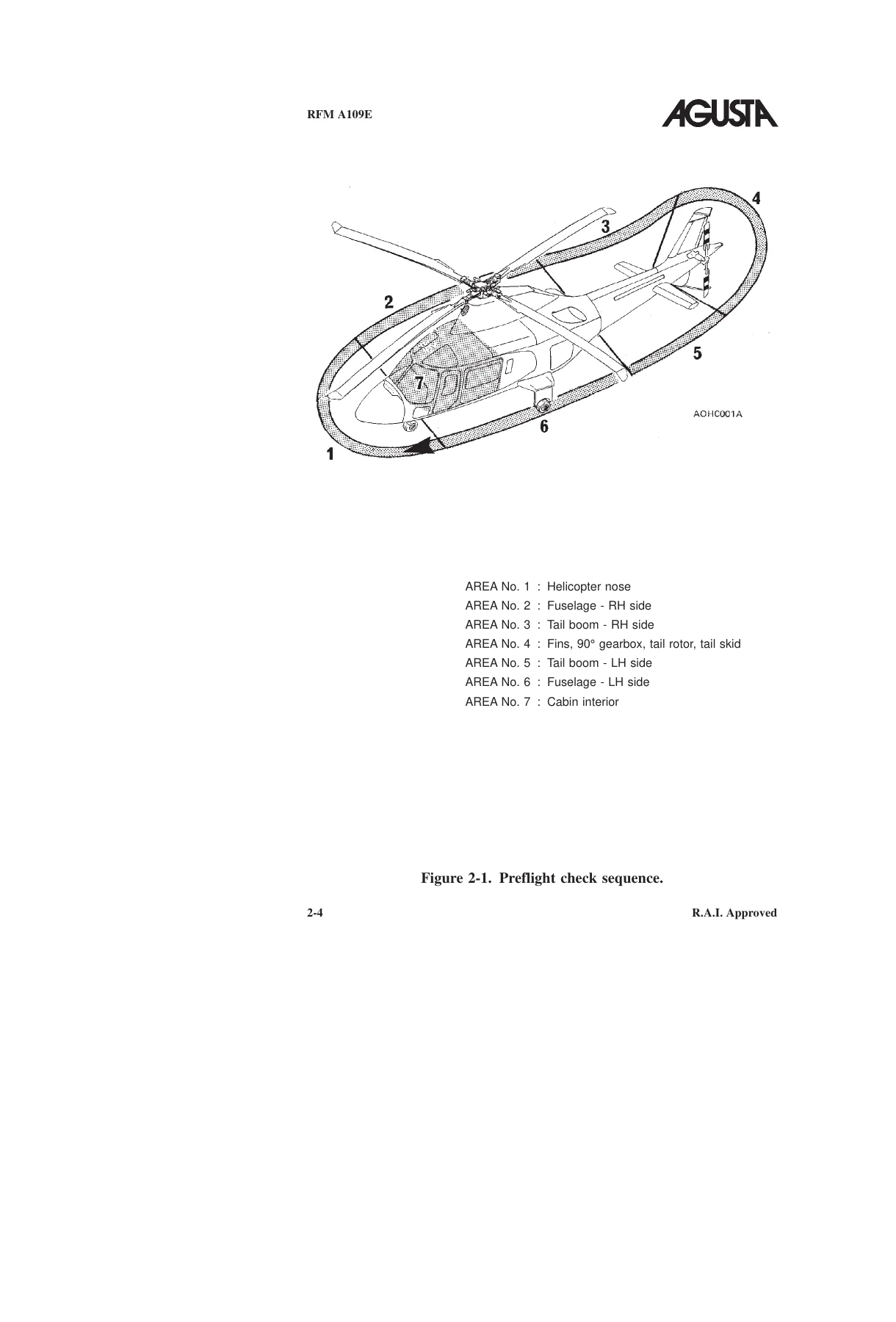
The normal-procedures section follows the operating sequence from planning through shutdown. It includes flight planning, takeoff and landing data references, weight-and-balance checks, a detailed daily preflight walk-around, the every-flight preflight check, engine pre-start configuration, normal and quick engine-start procedures, false-start and dry-motoring procedures, system checks, taxiing, hover and rolling takeoffs, in-flight operation, flight-director operation where installed, approach and landing, shutdown and post-flight checks. The illustrated preflight sequence identifies inspection areas around the nose, fuselage, tail boom, tail gearbox, tail rotor, cabin and related systems.

Emergency and Malfunction Procedures

A major part of the Agusta A109E Rotorcraft Flight Manual with Supplements – PW206C PDF is devoted to abnormal and emergency operation. The manual explains the warning system, master warning and master caution indications, EDU warning/caution messages and aural alerts before moving into fault-specific procedures. Engine failures include one-engine and two-engine failures, hot starts, in-flight restart, ECU malfunctions, AUTO-to-MANUAL transfer, engine operation in MANUAL mode, return to AUTO mode, manual-mode ground starts and shutdown, and RPM-switch malfunction.

Complete PDF Bookmark Tree

Complete Bookmarks

The complete bookmarks in the “Agusta A109E Rotorcraft Flight Manual with Supplements – PW206C PDF” are as follows:

List of Temporary Revisionsp. 6
Inactive Temporary Revisionsp. 6
Active Temporary Revisionsp. 6
List of Revised Pages / EASAp. 8
Revision 1 to 3p. 8
Revision 4p. 8
Revision 5 to 11p. 9
Revision 12 to 18p. 10
Revision 19p. 10
Revision 20 to 26p. 11
Revision 27 to 28p. 11
Revision 29 to 35p. 12
Revision 36p. 13
List of Revised Pages / FAAp. 14
Revision 1 to 4p. 14
Revision 5p. 14
Revision 6 to 11p. 15
Revision 12 to 18p. 16
Revision 19 to 23p. 17
Revision 24 to 26p. 17
Revision 27 to 35p. 18
Log of Pagesp. 20
Page B1p. 20
Page B2p. 21
Page B3p. 22
Page B4p. 23
Page B5p. 24
Page B6p. 25
Log of Pages / FAAp. 26
Page B1p. 26
Page B2p. 27
Page B3p. 28
Page B4p. 29
Page B5p. 30
Page B6p. 31
Table of Contentsp. 32
Introductionp. 34
Generalp. 34
Terminologyp. 34
Use Of Procedural Wordsp. 35
Abreviationsp. 35
All Dimensionsp. 38
PART 1 / RAI Approvedp. 40
Section 1 / Limitationsp. 42
TABLE OF CONTENTSp. 42
Generalp. 46
Basis of certificationp. 46
Type of operationp. 46
VFR operationp. 46
Flight with doors removedp. 46
IFR operationp. 47
Required equipment for IFR single pilotp. 47
Required equipment for IFR single pilot FAA Pagep. 48
Flight with one of the two helipilots inoperativep. 47
Optional Equipmentp. 50
Flight crewp. 50
Number of seatsp. 50
Airspeed limitationsp. 50
VNE (Power ON)p. 51
VNE (Power OFF/OEI)p. 52
Ground speed limitationsp. 53
Weight limitationsp. 53
Baggage compartmentp. 58
Center of gravity limitationsp. 53
Longitudinal limitations Millimetersp. 54
Longitudinal limitations (Inches)p. 55
Lateral limitations (Millimeters)p. 56
Lateral limitations (Inches)p. 57
Altitude limitationsp. 60
Temperature Limitationsp. 60
Power Plant limitationsp. 60
N1 limitationsp. 60
N2 limitationsp. 61
TOT limitationsp. 62
Rotor limitationsp. 62
Power ON (AEO)p. 62
Power ON (OEI)p. 63
Power OFFp. 63
Transmission Limitationp. 63
All engines operativep. 63
One engine inoperative (OEI)p. 64
Fuel limitationsp. 64
Engine lubricationp. 66
Oil Pressurep. 66
Oil temperaturep. 66
Approved lubricanting oilsp. 66
Main Transmissionp. 68
Oil pressurep. 68
Oil temperaturep. 68
Approved lubricant oilsp. 68
Tail rotor lubricantp. 69
Engine Start Limitationsp. 69
Generator limitationsp. 69
Main hydraulic limitationsp. 70
Utility Hydraulic limitationsp. 70
Instrument markingsp. 71
Eletronic display unit (formats)p. 74
Reversionary modep. 78
EDU 1 limits indicationp. 79
N1 (AEO)p. 79
N1 (OEI)p. 80
TOT Start/Cruise (AEO)p. 81
TOT (OEI)p. 82
Torque Start/cruise (AEO)p. 83
Torque OEI/Reversionary modep. 84
Rotor/N2 Start/Cruise(AEO)p. 85
Rotor autorotation modep. 86
Rotor/N2 OEI /Reversionary OEI Modep. 87
EDU 2 limits indicationp. 88
Engine oil pressurep. 88
Engine oil temperaturep. 89
Transmission oil (pressure and Temperature)p. 90
Main hydraulic pressurep. 91
Fuel Pressurep. 92
Ammeterp. 93
Normal Utility Pressurep. 94
Emergency utility pressurep. 95
EDU 1p. 76
Start Modep. 75
Cruise modep. 75
OEI modep. 76
Autorotation modep. 76
EDU 2p. 76
Main modep. 77
Auxiliary modep. 78
Placardsp. 96
VNEp. 96
Section 2 / Normal Proceduresp. 102
TABLE OF CONTENTSp. 102
Introductionp. 104
Flight planningp. 104
Take-off and landing datap. 105
Weight and balance datap. 105
Preflight checksp. 105
Pilot's daily preflight checkp. 106
Area N°1 (Helicopter nose)p. 106
Area N°2 ( Fuselage-rh side )p. 108
Area N°3 ( Tail boom- rh side )p. 112
Area N°4 ( fins, tail gearbox, tail rotor and skid)p. 112
Area N°5 ( tail boom-lh side )p. 113
Area N°6 ( Fuselage-lh side )p. 113
Area N°7 ( cabin interior )p. 116
Pilot's preflight checkp. 119
Engine pre-start checkp. 124
Normal engine startp. 132
Engine 1 startp. 134
Engine 2 startp. 137
Quick engine startp. 138
False startp. 143
Dry motoring runp. 143
Systems checkp. 144
Taxiingp. 151
Take-offp. 151
Hover take-offp. 151
Rolling take-offp. 153
In flightp. 154
Flight director operationp. 155
Attitude mode operationp. 155
VOR/NAV Operationp. 156
GO-AROUND modep. 157
Approach angle VS airspeedp. 157
Approach and landingp. 157
Shutdownp. 161
Post flight checkp. 163
Section 3 / Emergency & Malfunction Proceduresp. 164
TABLE OF CONTENTSp. 164
Introductionp. 166
Definitionsp. 166
Warning systemp. 167
Cockpit layout of the warning and caution systemp. 169
Master caution and warning lightsp. 170
Warning caution and aural messagesp. 171
Warning messages (RED)p. 172
Batt Dischp. 173
Batt hotp. 173
Electricalp. 174
Eng 1 (2) firep. 172
Eng 1 (2) outp. 172
Rotor lowp. 172
Rotor highp. 172
XMSN oil hotp. 173
XMSN oil presp. 172
#1 (#2) Oil Presp. 173
#1 (#2) ECU failp. 174
Caution messages (Yellow)p. 176
ATTD OFFp. 183
AWG Failp. 183
Bag Doorp. 182
Bat OFFp. 178
Bus Tiep. 178
Cabin Doorp. 182
DAU MISCMP-Pp. 187
Emer Util Chrgp. 182
Emer Util Presp. 180
Ext Pwr ONp. 178
FUEL DRAIN 1 (2)p. 178
Fuel pump 1(2)p. 177
IDSp. 187
INV 1 (2)p. 183
Landing gearp. 182
Main Util Chrgp. 180
Main Util Presp. 180
Park Brk ONp. 182
RPM Selectp. 186
SAS 1 OFFp. 182
SAS 2 OFFp. 183
Servo 1 (2)p. 178
Tail oil chipp. 177
TRQ Limiterp. 186
VG1p. 183
VG2p. 183
XMSN oil chipp. 176
XMNS OVTRQp. 183
#1 (#2) A/F F FLTRp. 177
#1 (#2) DC GENp. 178
#1 (#2) DCUp. 184
#1 (#2) ECU DATAp. 185
#1 (#2) ECU Maintp. 184
#1 (#2) Fire Detp. 184
#1 (#2) FUEL FLTRp. 178
#1 (#2) Fuel lowp. 177
#1 (#2) F low Failp. 177
#1 (#2) Gen CTLp. 185
#1 (#2) Oil chipp. 176
#1 (#2) Oil hotp. 176
#1 (#2) OVSPDp. 179
#1 (#2) OVSP DETp. 180
#1 (#2) OVSPD TESTp. 185
#1 (#2) PLAp. 184
#1 (#2) PLA Motorp. 185
#1 (#2) PMSp. 184
#1 (#2) TOT Limiterp. 186
Engine Failuresp. 188
Auto mode to Manual Mode Transferp. 198
Engine Control Unit Malfunctionsp. 197
Engine Hot Startp. 191
Engine Operation in Manual Modep. 199
One Engine in Manual Mode And One Engine in Auto Modep. 199
Both Engines in Manual Modep. 200
Engine Start in Manual Mode (On Ground)p. 203
Engine Shutdown in manual modep. 205
Engine Restart in flightp. 192
Engine Restart in flight (Auto Mode)p. 192
Engine Restart in flight (Manual Mode)p. 194
Failure of one enginep. 188
Failure of two enginesp. 189
Manual Mode to Auto Mode Transferp. 202
RPM Switch malfunctionp. 206
Drive System Failuresp. 207
Tail Rotor Failurep. 207
Complete Loss Of Tail Rotor Control in Hoveringp. 208
Complete Loss Of Tail Rotor In Crusiep. 209
System Failurep. 210
Autotrim malfunctionp. 239
Electrical Power Failure (Helicopters equipped with emergency bus)p. 224
Bus Tiep. 224
BUS TIE, INV2, SAS1 OFF and electrical and BATT DISCH warnigsp. 225
Electrical and BATT DISCHp. 224
Failure of a generatorp. 225
Failure of an AC bus system- 115V and 26Vp. 236
Failure of an inverterp. 236
Failure of both generatorsp. 231
Failure of both generators bussesp. 227
Failure of generator bus #1 or #2p. 226
Failure of genertor 1 or 2 and generator bus #1 or #2p. 229
Failure of generator 1 and generator bus #2p. 227
Failure of generator 2 and generator bus #1p. 228
Failure of both generators and both generators bussesp. 233
INV1 or 2p. 225
#1 (#2) DC GENp. 224
#1 DC GEN, B US TIE, INV2 SAS2 OFFp. 224
#1 (#2) DC GEN, BUS TIE and BATT DISCHp. 224
Electrical Power Failure (Helicopters not equipped with emergency bus)p. 214
BUS TIEp. 214
Failure of a generatorp. 215
Failure of an AC bus system-115V and 26Vp. 223
Failure of an inverterp. 222
Failure of both generatorsp. 220
Failure of both generator bussesp. 216
Failure of generator bus #1 or #2p. 216
Failure of generator 1 or 2 and generator #1 or #2p. 219
Failure of generator 1 and generator bus #2p. 217
Failure of generator 2 and generator bus #1p. 218
Failure of both generators and both generators bussesp. 222
INV 1 or 2p. 215
SAS 1 (2) OFF-VG1 (2)p. 215
#1 and #2 DC GENp. 215
#1 and #2 DC GEN, BUS TIE, INV1, INV2, SAS1 OFF, SAS2 OFFp. 215
#1(#2) DC GENp. 214
#1(#2) DC GEN, BUS TIEp. 214
#1(#2) DC GEN, BUS TIE, INV1(2), SAS1(2)p. 215
EMERGENCY PROCEDURE FOR LIMIT OVERRIDE PUSHBUTTON OPERATIONp. 249
FIREp. 245
Engine Firep. 245
Fire during startp. 245
Fire in flightp. 246
Smoke in cabin, toxic fumes, ETCp. 247
Flight in Thunderstorm-Lightningp. 248
Helipilot malfunctionp. 237
Oscillatory malfunctions during pitch,roll or yaw helipilot operationp. 238
Repeated disturbances during pitch,roll or yaw helipilot operationp. 238
Integrated Display Failurep. 240
Coplete loss of primary (Main and backp) or secundary parametersp. 242
EDU failurep. 240
EDU display degradationp. 240
Failure of both EDUsp. 241
Falure of Both DAU channelsp. 244
Failure of one DAU channelp. 243
Loss of ECU parameterp. 241
Miscompare of DAU primary parametersp. 242
Intercommunication system failurep. 239
Jamming of A Servo Valvep. 212
Landing Gear malfunctionp. 213
RAD-MSTRp. 237
Servo Hydraulic System Malfunctionp. 210
Pressure Loss in N°1 Main Hydraulic Systemp. 210
Pressure Loss in N°2 Main Hydraulic Systemp. 212
Static Port Obstructionp. 248
Section 4 / Performance Datap. 252
TABLE OF CONTENTSp. 252
Introductionp. 254
POWER ASSURANCE CHECKSp. 254
POWER ASSURANCE CHECK HOVERp. 256
POWER ASSURANCE CHECK IN FLIGHTp. 257
DENSITY ALTITUDEp. 258
DENSITY ALTITUDE CHARTp. 259
CONVERSION CHARTp. 260
OPERATION VS ALLOWABLE WINDp. 261
Wind/ground speed azimuth envelope UP TO 4000 Ft.p. 261
Wind/ground speed azimuth envelope From 4000 Ft to 8000 Ft.p. 262
HOVERING CEILING IGEp. 263
HOVERING CEILING IN GROUND EFFECT TAKE-OFF POWERp. 264
HOVERING CEILING IN GROUND EFFECT MAXIMUM CONTINUOUS POWERp. 265
HOVERING CEILING OGEp. 266
HOVERING CEILING OUT OF GROUND EFFECT TAKE-OFF POWERp. 267
HOVERING CEILING OUT OF GROUND EFFECT MAXIMUM CONTINUOUS POWERp. 268
HEIGHT – VELOCITY DIAGRAMp. 269
HEIGHT-VELOCITY DIAGRAM ONE ENGINE INOPERATIVE CHART Ap. 270
HEIGHT-VELOCITY DIAGRAM ONE ENGINE INOPERATIVE CHART Bp. 271
RATE OF CLIMBp. 272
All Enginesp. 273
take-off power – 2050 kg.p. 273
take-off power – 2450 kg.p. 274
take-off power – 2850 kg.p. 275
maximum continuous power – 2050 kg.p. 276
maximum continuous power – 2450 kg.p. 277
maximum continuous power – 2850 kg.p. 278
One Engine (OEI)p. 279
2.5 minutes power – 2050 kg.p. 279
2.5 minutes power – 2450 kg.p. 280
2.5 minutes power – 2850 kg.p. 281
maximum continuous power – 2050 kg.p. 282
maximum continuous power – 2450 kg.p. 283
maximum continuous power – 2850 kg.p. 284
AIRSPEED CALIBRATIONp. 285
Airspeed calibration curve pilot (forward flight).p. 286
Airspeed calibration curve copilot (forward flight).p. 287
NOISE CHARACTERISTICSp. 288
Section 5 / Optional Equipmentp. 290
LIST OF APPENDICESp. 290
1 to 12p. 290
13 to 28p. 291
29 to 44p. 292
OPTIONAL EQUIPMENT INCOMPATIBILITYp. 293
Appendix 1 to 20p. 293
Appendix 21 to 44p. 294
LIST OF SUPPLEMENTSp. 295
Rotor brakep. 296
TABLE OF CONTENTSp. 297
SECTION 1 – LIMITATIONSp. 298
CENTER OF GRAVITY LIMITATIONSp. 298
PLACARDSp. 298
SECTION 2 – NORMAL PROCEDURESp. 298
PILOT’S DAILY PREFLIGHT CHECKp. 298
(First flight of the day)p. 298
PILOT’S PREFLIGHT CHECKp. 299
(Every flight)p. 299
ENGINE PRE-START CHECKp. 299
ENGINE STARTp. 299
SHUTDOWNp. 300
POST FLIGHT CHECKp. 300
SECTION 3 – EMERGENCY AND MALFUNCTION PROCEDURESp. 300
CAUTION MESSAGES (YELLOW)p. 300
SECTION 4 – PERFORMANCE DATAp. 300
ENGINE COMPARTMENT FIRE EXTINGUISHERSp. 302
TABLE OF CONTENTSp. 303
SECTION 1 – LIMITATIONSp. 304
CENTER OF GRAVITY LIMITATIONSp. 304
SECTION 2 – NORMAL PROCEDURESp. 304
PREFLIGHT CHECKSp. 304
PILOT’S DAILY PREFLIGHT CHECKp. 304
PILOT’S PREFLIGHT CHECKp. 305
ENGINE PRE-START CHECKp. 305
SECTION 3 – EMERGENCY AND MALFUNCTION PROCEDURESp. 306
WARNING SYSTEMp. 306
WARNING MESSAGES (RED)p. 306
FIREp. 307
ENGINE FIREp. 307
ENGINE FIRE DURING STARTp. 307
ENGINE FIRE IN FLIGHTp. 308
SECTION 4 – PERFORMANCE DATAp. 309
LIST OF ILLUSTRATIONSp. 303
Figure 3-1. Control panel on the overhead console.p. 306
WEATHER RADAR – RDR 2000 BENDIX KINGp. 310
TABLE OF CONTENTSp. 311
SECTION 1 – LIMITATIONSp. 312
CENTER OF GRAVITY LIMITATIONSp. 312
SECTION 2 – NORMAL PROCEDURESp. 312
WEATHER RADAR OPERATIONp. 312
SECTION 3 – EMERGENCY AND MALFUNCTION PROCEDURESp. 313
SECTION 4 – PERFORMANCE DATAp. 313
PULSED CHIP DETECTORp. 314
TABLE OF CONTENTSp. 315
SECTION 1 – LIMITATIONSp. 316
SECTION 2 – NORMAL PROCEDURESp. 316
SECTION 3 – EMERGENCY AND MALFUNCTION PROCEDURESp. 316
CAUTION MESSAGES (YELLOW)p. 316
XSMN OIL CHIPp. 316
TGB OIL CHIPp. 317
# 1 (# 2) OIL CHIPp. 318
SECTION 4 – PERFORMANCE DATAp. 318
ENVIRONMENTAL CONTROL SYSTEM (AIR CONDITIONING)p. 320
TABLE OF CONTENTSp. 321
SECTION 1 – LIMITATIONSp. 322
ECS OPERATIONp. 322
CENTER OF GRAVITY LIMITATIONSp. 322
SECTION 2 – NORMAL PROCEDURESp. 322
ENGINE PRE-START CHECKp. 322
SYSTEMS CHECKp. 322
ENVIRONMENTAL CONTROL SYSTEM OPERATIONAL CHECKp. 322
IN FLIGHT (ABOVE 200 FT AGL)p. 321
APPROACH AND LANDING (BELOW 200 FT AGL)p. 324
SECTION 3 – EMERGENCY AND MALFUNCTION PROCEDURESp. 325
ENGINE FAILURESp. 321
FAILURE OF ONE ENGINEp. 325
FAILURE OF TWO ENGINESp. 325
ENGINE RESTART IN FLIGHTp. 325
FIREp. 325
ENGINE FIRE IN FLIGHTp. 325
SMOKE IN CABIN, TOXIC FUMES, ETC.p. 326
ENVIRONMENTAL CONTROL SYSTEM MALFUNCTIONp. 326
SECTION 4 – PERFORMANCE DATAp. 326
GENERALp. 326
List of Performance Data Charts:p. 326
Figure 4-1. Hovering ceiling – IGE – take-off power.p. 328
Figure 4-2. Hovering ceiling – IGE – maximum continuous power.p. 329
Figure 4-3. Hovering ceiling – OGE – take-off power.p. 330
Figure 4-4. Hovering ceiling – OGE – maximum continuous power.p. 331
Figure 4-5. Rate of climb – all engines – take-off power – 2050 kg.p. 332
Figure 4-6. Rate of climb – all engines – take-off power – 2450 kg.p. 333
Figure 4-7. Rate of climb – all engines – take-off power – 2850 kg.p. 334
Figure 4-8. Rate of climb – all engines – maximum continuous power – 2050 kg.p. 335
Figure 4-9. Rate of climb – all engines – maximum continuous power – 2450 kg.p. 336
Figure 4-10. Rate of climb – all engines – maximum continuous power – 2850 kg.p. 337
BLEED-AIR HEATERp. 338
TABLE OF CONTENTSp. 339
SECTION 1 – LIMITATIONSp. 340
BLEED AIR OPERATIONp. 340
CENTER OF GRAVITY LIMITATIONSp. 340
PLACARDSp. 340
SECTION 2 – NORMAL PROCEDURESp. 340
ENGINE PRE-START CHECKp. 340
SYSTEMS CHECKp. 341
BLEED-AIR HEATER OPERATIONAL CHECKp. 341
IN FLIGHT (ABOVE 200 FT AGL)p. 342
APPROACH AND LANDING (BELOW 200 FT AGL)p. 342
SECTION 3 – EMERGENCY AND MALFUNCTION PROCEDURESp. 343
ENGINE FAILURESp. 343
FAILURE OF ONE ENGINEp. 343
FAILURE OF TWO ENGINESp. 343
ENGINE RESTART IN FLIGHTp. 343
FIREp. 344
ENGINE FIRE IN FLIGHTp. 344
SMOKE IN CABIN, TOXIC FUMES, ETC.p. 344
HEATER MALFUNCTIONp. 344
SECTION 4 – PERFORMANCE DATAp. 345
GENERALp. 345
List of Performance Data Charts:p. 345
Figure 4-1. Hovering ceiling – IGE – take-off power.p. 346
Figure 4-2. Hovering ceiling – IGE – maximum continuous power.p. 347
Figure 4-3. Hovering ceiling – OGE – take-off power.p. 348
Figure 4-4. Hovering ceiling – OGE – maximum continuous power.p. 349
Figure 4-5. Rate of climb – all engines – take-off power – 2050 kg.p. 350
Figure 4-6. Rate of climb – all engines – take-off power – 2450 kg.p. 351
Figure 4-7. Rate of climb – all engines – take-off power – 2850 kg.p. 352
Figure 4-8. Rate of climb – all engines – maximum continuous power – 2050 kg.p. 353
Figure 4-9. Rate of climb – all engines – maximum continuous power – 2450 kg.p. 354
Figure 4-10. Rate of climb – all engines – maximum continuous power – 2850 kg.p. 355
SEARCHLIGHTp. 356
TABLE OF CONTENTSp. 357
SECTION 1 – LIMITATIONSp. 358
AIRSPEED LIMITATIONS (KIAS)p. 358
CENTER OF GRAVITY LIMITSp. 358
SECTION 2 – NORMAL PROCEDURESp. 358
PREFLIGHT CHECKSp. 358
PILOT’S DAILY PREFLIGHT CHECKp. 358
PILOT’S PREFLIGHT CHECKp. 358
ENGINE PRE-START CHECKp. 359
IN FLIGHTp. 359
SEARCHLIGHT OPERATING PROCEDUREp. 359
EXTENSIONp. 359
RETRACTIONp. 360
SECTION 3 – EMERGENCY AND MALFUNCTION PROCEDURESp. 360
SECTION 4 – PERFORMANCE DATAp. 360
SUPPLEMENTARY FUEL TANKSp. 362
TABLE OF CONTENTSp. 363
SECTION 1 – LIMITATIONSp. 364
CENTER OF GRAVITY LIMITATIONSp. 364
SECTION 2 – NORMAL PROCEDURESp. 364
ENGINE PRE-START CHECKp. 364
SECTION 3 – EMERGENCY AND MALFUNCTION PROCEDURESp. 364
SECTION 4 – PERFORMANCE DATAp. 364
PART II – MANUFACTURER’S DATAp. 365
SECTION 6 – WEIGHT AND BALANCEp. 365
WEIGHTS – ARMS AND MOMENTSp. 365
LONGITUDINAL MOMENTSp. 365
LATERAL MOMENTSp. 368
SECTION 8 – HANDLING AND SERVICINGp. 369
SERVICINGp. 369
″GREEN AIRCRAFT″ CONFIGURATIONp. 370
TABLE OF CONTENTSp. 371
SECTION 1 – LIMITATIONSp. 372
FLIGHT CREWp. 372
NUMBER OF SEATSp. 372
SECTION 2 – NORMAL PROCEDURESp. 372
SECTION 3 – EMERGENCY AND MALFUNCTION PROCEDURESp. 372
SECTION 4 – PERFORMANCE DATAp. 372
E.M.S. EMERGENCY MEDICAL SERVICEp. 374
TABLE OF CONTENTSp. 376
SECTION 1 – LIMITATIONSp. 378
TYPE OF OPERATIONp. 378
REQUIRED EQUIPMENTp. 378
VFR OPERATIONp. 378
FLIGHT WITH PASSENGER CABIN DOORS OPEN OR REMOVEDp. 378
FLIGHT CREWp. 378
NUMBER OF SEATSp. 378
BAGGAGE COMPARTMENT LIMITATIONSp. 379
CENTER OF GRAVITY LIMITATIONSp. 379
PLACARDSp. 379
SECTION 2 – NORMAL PROCEDURESp. 379
PREFLIGHT CHECKSp. 379
PILOT’S DAILY PREFLIGHT CHECKp. 379
PILOT’S PREFLIGHT CHECKp. 380
ENGINE PRE-START CHECKp. 381
LITTER OPERATIONSp. 382
LITTER(S) LOADINGp. 382
LITTER(S) UNLOADINGp. 382
OXYGEN SYSTEM OPERATIONSp. 382
SECTION 3 – EMERGENCY AND MALFUNCTION PROCEDURESp. 383
WARNING SYSTEMp. 383
CAUTION MESSAGES (YELLOW)p. 383
UTIL DOORp. 383
EVACUATION THROUGH EMERGENCY EXITSp. 383
SECTION 4 – PERFORMANCE DATAp. 383
PART II – MANUFACTURER’S DATAp. 377
SECTION 6 – WEIGHT AND BALANCEp. 384
LITTER ARM (-113/-179, -119/-165, -137/-173, -143 AND 183)p. 384
LITTERS ARM (-127/-171 AND -145) 11 of 15 FORWARD SEAT ARM (-113/-179, -119/-165, -137/- 173, -143 AND -183)p. 384
FORWARD SEAT ARM (-113/-179, -119/-165, -137/- 173, -143 AND -183)p. 384
FORWARD SEATS ARM (-131 ONLY)p. 384
AFT SEAT ARM (-113/-179, -119/-165, -137/-173, -143 AND -183)p. 384
AFT SEAT ARM (-127/-171 AND -145)p. 385
AFT SEATS ARM (-131 ONLY)p. 385
SECTION 7 – SYSTEMS DESCRIPTIONp. 386
LIST OF ILLUSTRATIONSp. 377
Figure 7-1. (sheet 1 of 2) E.M.S. Interior arrangment.p. 386
Figure 7-1. (sheet 2 of 2) E.M.S. Interior arrangment.p. 387
Figure 7-2. Oxygen manual shu-off handle.p. 388
SLIDING DOORSp. 390
TABLE OF CONTENTSp. 391
SECTION 1 – LIMITATIONSp. 392
VFR OPERATIONp. 392
IFR OPERATIONp. 392
AIRSPEED LIMITATIONS (KIAS)p. 392
CENTER OF GRAVITY LIMITATIONSp. 392
PLACARDSp. 393
SECTION 2 – NORMAL PROCEDURESp. 393
PILOT’S DAILY PREFLIGHT CHECKp. 393
IN FLIGHTp. 394
SECTION 3 – EMERGENCY AND MALFUNCTION PROCEDURESp. 394
SECTION 4 – PERFORMANCE DATAp. 394
EQUIVALENT CATEGORY ″A″ OPERATIONSp. 396
TABLE OF CONTENTSp. 397
GENERAL INFORMATIONp. 402
DEFINITIONSp. 402
Backup distancep. 404
Balked landingp. 404
Balked landing distancep. 404
CAT – A landingp. 402
CAT – A take-offp. 402
Clear areap. 404
Congested areap. 405
Helipadp. 404
Landing distancep. 404
Landing decision point (LDP)p. 403
Rejected takeoff distancep. 403
Short fieldp. 404
Takeoff distancep. 403
Takeoff decision point (TDP)p. 403
Takeoff flight pathp. 403
Takeoff safety speed or balked landing safety speed (V2)p. 403
ABBREVIATIONSp. 405
SECTION 1 – LIMITATIONSp. 406
TYPE OF OPERATIONp. 406
REQUIRED EQUIPMENTp. 406
GROUND SPEED LIMITATIONSp. 406
WEIGHT LIMITATIONSp. 407
Figure 1-1. Weight – altitude – temperature limitations for takeoff and landing (clear area).p. 407
Figure 1-2. Weight – altitude – temperature limitations for takeoff and landing (short field)p. 408
Figure 1-3. Weight – altitude – temperature limitations for takeoff and landing (ground based helipad/elevated helipad)p. 409
ALTITUDE LIMITATIONSp. 410
CROSSWIND LIMITATIONSp. 410
SECTION 2 – NORMAL PROCEDURESp. 411
OPERATION FROM CLEAR AREAp. 411
GENERAL DATAp. 411
TAKEOFF DECISION POINT (TDP)p. 411
LANDING DECISION POINT (LDP)p. 411
TAKEOFFp. 412
TAKEOFF FROM CLEAR AREAp. 412
APPROACH AND LANDINGp. 415
LANDING ON CLEAR AREAp. 415
OPERATION ON SHORT FIELDp. 417
GENERAL DATAp. 417
TAKEOFF DECISION POINT (TDP)p. 418
LANDING DECISION POINT (LDP)p. 418
TAKEOFFp. 418
TAKEOFF FROM SHORT FIELDp. 418
APPROACH AND LANDINGp. 421
LANDING ON SHORT FIELDp. 421
HELIPAD OPERATION (GROUND LEVEL OR ELEVATED)p. 424
GENERAL DATAp. 424
TAKEOFF DECISION POINT (TDP)p. 424
LANDING DECISION POINT (LDP)p. 424
TAKEOFFp. 425
TAKEOFF FROM HELIPADp. 425
APPROACH AND LANDINGp. 430
LANDING ON HELIPADp. 430
SECTION 3 – EMERGENCY AND MALFUNCTION PROCEDURESp. 434
INTRODUCTIONp. 434
WARNING SYSTEMp. 434
WARNING MESSAGES (RED)p. 435
Takeoff (prior to TDP)p. 435
ROTOR HIGHp. 435
ENG 1 (2) OUTp. 435
ENG 1 (2) FIREp. 435
XMSN OIL PRESp. 435
XMSN OIL HOTp. 435
BATT HOTp. 435
#1 (#2) ECU FAILp. 435
Takeoff (after TDP)p. 436
ROTOR LOWp. 436
ROTOR HIGHp. 436
ENG 1 (2) OUTp. 436
ENG 1 (2) FIREp. 436
XMSN OIL PRESp. 437
XMSN OIL HOTp. 437
BATT HOTp. 437
#1 (#2) ECU FAILp. 437
Landing (prior to LDP)p. 438
ROTOR LOWp. 438
ROTOR HIGHp. 438
ENG 1 (2) OUTp. 438
ENG 1 (2) FIREp. 439
XMSN OIL PRESp. 439
XMSN OIL HOTp. 439
BATT HOTp. 439
#1 (#2) ECU FAILp. 439
Landing (after LDP)p. 440
ROTOR LOWp. 440
ROTOR HIGHp. 440
ENG 1 (2) OUTp. 440
ENG 1 (2) FIREp. 440
XMSN OIL PRESp. 440
XMSN OIL HOTp. 441
BATT HOTp. 441
#1 (#2) ECU FAILp. 441
EMERGENCY PROCEDURES FOR OPERATION ON CLEAR AREAp. 442
ENGINE FAILURE DURING TAKEOFF PRIOR TO/AT THE TAKEOFF DECISION POINT (TDP)p. 442
ENGINE FAILURE DURING TAKEOFF AT/AFTER THE TAKEOFF DECISION POINT (TDP)p. 443
ENGINE FAILURE DURING LANDING PRIOR TO/AT THE LANDING DECISION POINT (LDP)p. 445
ENGINE FAILURE DURING LANDING AT/AFTER THE LANDING DECISION POINT (LDP)p. 446
EMERGENCY PROCEDURES FOR OPERATION ON SHORT FIELDp. 448
ENGINE FAILURE DURING TAKEOFF PRIOR TO/AT THE TAKEOFF DECISION POINT (TDP)p. 448
ENGINE FAILURE DURING TAKEOFF AT/AFTER THE TAKEOFF DECISION POINT (TDP)p. 450
ENGINE FAILURE DURING LANDING PRIOR TO/AT THE LANDING DECISION POINT (LDP)p. 451
ENGINE FAILURE DURING LANDING AT/AFTER THE LANDING DECISION POINT (LDP)p. 453
EMERGENCY PROCEDURES FOR OPERATION ON HELIPAD (GROUND LEVEL OR ELEVATED)p. 455
ENGINE FAILURE DURING TAKEOFF PRIOR TO/AT THE TAKEOFF DECISION POINT (TDP)p. 455
ENGINE FAILURE DURING TAKEOFF AT/AFTER THE TAKEOFF DECISION POINT (TDP)p. 456
ENGINE FAILURE DURING LANDING PRIOR TO/AT THE LANDING DECISION POINT (LDP)p. 458
ENGINE FAILURE DURING LANDING AT/AFTER THE LANDING DECISION POINT (LDP)p. 459
SECTION 4 – PERFORMANCE DATAp. 461
POWER ASSURANCE CHECKp. 461
WIND EFFECTp. 461
Figure 4-1. Wind component chart.p. 462
OPERATION FROM CLEAR AREAp. 463
TAKEOFF DISTANCEp. 463
REJECTED TAKEOFF DISTANCEp. 463
LANDING DISTANCEp. 463
BALKED LANDING DISTANCEp. 463
OPERATION ON SHORT FIELDp. 464
TAKEOFF DISTANCEp. 464
REJECTED TAKEOFF DISTANCEp. 464
LANDING DISTANCEp. 464
BALKED LANDING DISTANCEp. 464
HELIPAD OPERATION (GROUND LEVEL OR ELEVATED)p. 465
TAKEOFF DISTANCEp. 465
BACKUP DISTANCEp. 465
LANDING DISTANCEp. 465
BALKED LANDING DISTANCEp. 465
TAKEOFF FLIGHT PATH 1p. 466
MEAN HEIGHT GAINED IN 30 M HORIZONTAL DISTANCEp. 466
Takeoff flight path 1 – 2050 kg.p. 467
Takeoff flight path 1 – 2250 kg.p. 468
Takeoff flight path 1 – 2450 kg.p. 469
Takeoff flight path 1 – 2650 kg.p. 470
Takeoff flight path 1 – 2850 kg.p. 471
TAKEOFF FLIGHT PATH 2p. 472
MEAN HEIGHT GAINED IN 30 M HORIZONTAL DISTANCEp. 472
Takeoff flight path 2 – 2050 kg.p. 473
Takeoff flight path 2 – 2250 kg.p. 474
Takeoff flight path 2 – 2450 kg.p. 475
Takeoff flight path 2 – 2650 kg.p. 476
Takeoff flight path 2 – 2850 kg.p. 477
CLIMB PERFORMANCEp. 478
SINGLE ENGINE RATE OF CLIMB AT V2 (30 KTS IAS)p. 478
2.5 minutes power – 2050 kg.p. 479
2.5 minutes power – 2250 kg.p. 480
2.5 minutes power – 2450 kg.p. 481
2.5 minutes power – 2650 kg.p. 482
2.5 minutes power – 2850 kg.p. 483
SINGLE ENGINE RATE OF CLIMB AT VY (60 KTS IAS)p. 478
LIST OF ILLUSTRATIONSp. 400
Figure 1-1. Weight – altitude – temperature limitations for takeoff and landing (clear area).p. 407
Figure 1-2. Weight – altitude – temperature limitations for takeoff and landing (short field).p. 408
Figure 1-3. Weight – altitude – temperature limitations for takeoff and landing (ground based helipad/ /elevated helipad).p. 409
Figure 2-1. Takeoff flight path profile from clear area.p. 412
Figure 2-2. Landing flight path profile on clear area.p. 415
Figure 2-3. Minimum field size and example of marking.p. 417
Figure 2-4. Takeoff profile from short field.p. 418
Figure 2-5. Landing profile on short field.p. 421
Figure 2-6. Takeoff profile from helipad.p. 425
Figure 2-7. Takeoff from helipad – view at 3 ft height.p. 428
Figure 2-8. Takeoff from helipad – view at TDP (80 ft).p. 429
Figure 2-9. Landing profile on helipad.p. 430
Figure 2-10. Landing on helipad – view at LDP (80 ft).p. 433
Figure 3-1. Rejected takeoff flight path profile (clear area).p. 442
Figure 3-2. Continued takeoff flight path profile (clear area).p. 443
Figure 3-3. Balked landing flight path profile (clear area).p. 445
Figure 3-4. OEI landing flight path profile (clear area).p. 446
Figure 3-5. Rejected takeoff flight path profile (short field).p. 448
Figure 3-6. Continued takeoff flight path profile (short field).p. 450
Figure 3-7. Balked landing flight path profile (short field).p. 451
Figure 3-8. OEI landing flight path profile (short field).p. 453
Figure 3-9. Rejected takeoff flight path profile (helipad).p. 455
Figure 3-10. Continued takeoff flight path profile (helipad).p. 456
Figure 3-11. Balked landing flight path profile (helipad).p. 458
Figure 3-12. OEI landing flight path profile (helipad).p. 459
Figure 4-1. Wind component chart.p. 462
Figure 4-2. Takeoff flight path 1 – 2050 kg.p. 467
Figure 4-3. Takeoff flight path 1 – 2250 kg.p. 468
Figure 4-4. Takeoff flight path 1 – 2450 kg.p. 469
Figure 4-5. Takeoff flight path 1 – 2650 kg.p. 470
Figure 4-6. Takeoff flight path 1 – 2850 kg.p. 471
Figure 4-7. Takeoff flight path 2 – 2050 kg.p. 473
Figure 4-8. Takeoff flight path 2 – 2250 kg.p. 474
Figure 4-9. Takeoff flight path 2 – 2450 kg.p. 475
Figure 4-10. Takeoff flight path 2 – 2650 kg.p. 476
Figure 4-11. Takeoff flight path 2 – 2850 kg.p. 477
Figure 4-12. Rate of climb – OEI – 2.5 minutes power – 2050 kg.p. 479
Figure 4-13. Rate of climb – OEI – 2.5 minutes power – 2250 kg.p. 480
Figure 4-14. Rate of climb – OEI – 2.5 minutes power – 2450 kg.p. 481
Figure 4-15. Rate of climb – OEI – 2.5 minutes power – 2650 kg.p. 482
Figure 4-16. Rate of climb – OEI – 2.5 minutes power – 2850 kg.p. 483
INTEGRATED DISPLAY SYSTEM CONFIGURATION EDU P/N 109-0900-42-101 DAU P/N 109-0900-42-103p. 484
TABLE OF CONTENTSp. 485
SECTION 1 – LIMITATIONSp. 486
TYPE OF OPERATIONp. 486
POWER PLANT LIMITATIONSp. 486
POWER TURBINE (N2) RPMp. 486
ROTOR LIMITATIONSp. 486
TRANSMISSION LIMITATIONSp. 487
TORQUE (TRQ%)p. 487
INSTRUMENT MARKINGSp. 488
ELECTRONIC DISPLAY UNIT FORMATSp. 488
Figure 1-1. EDU 1 – OEI mode.p. 488
Figure 1-2. EDU 1 – TORQUE (OEI).p. 489
Figura 1-3. EDU 1 – ROTOR POWER TURBINE SPEED (OEI).p. 490
SECTION 2 – NORMAL PROCEDURESp. 491
SECTION 3 – EMERGENCY AND MALFUNCTION PROCEDURESp. 491
EMERGENCY PROCEDURE FOR LIMIT OVERRIDE PUSHBUTTON OPERATIONp. 491
SECTION 4 – PERFORMANCE DATAp. 492
POWER ASSURANCE CHECKSp. 492
Figure 4-1. Power assurance check – hover.p. 494
Figure 4-2. Power assurance check – in flight.p. 495
LIST OF ILLUSTRATIONSp. 485
Figure 1-1. EDU 1 – OEI mode.p. 488
Figure 1-2. EDU 1 – TORQUE (OEI).p. 489
Figura 1-3. EDU 1 – ROTOR POWER TURBINE SPEED (OEI).p. 490
Figure 4-1. Power assurance check – hover.p. 494
Figure 4-2. Power assurance check – in flight.p. 495
BATTERY 22 AHp. 496
TABLE OF CONTENTSp. 497
SECTION 1 – LIMITATIONSp. 498
SECTION 2 – NORMAL PROCEDURESp. 498
SECTION 3 – EMERGENCY AND MALFUNCTION PROCEDURESp. 498
ELECTRICAL POWER FAILUREp. 498
Failure of both generatorsp. 498
SECTION 4 – PERFORMANCE DATAp. 499
EFIS (ELECTRONIC FLIGHT INSTRUMENT SYSTEM)p. 500
TABLE OF CONTENTSp. 501
SECTION 1 – LIMITATIONSp. 502
TYPE OF OPERATIONp. 502
PLACARDSp. 502
SECTION 2 – NORMAL PROCEDURESp. 502
PREFLIGHT CHECKSp. 502
ENGINE PRE-START CHECKSp. 502
NORMAL ENGINE STARTp. 503
ENGINE 2 STARTp. 503
QUICK ENGINE STARTp. 503
SYSTEMS CHECKp. 503
EADI instrument:p. 503
EHSI instrument:p. 504
SECTION 3 – EMERGENCY AND MALFUNCTION PROCEDURESp. 504
WARNING SYSTEMp. 504
CAUTION MESSAGES (YELLOW)p. 504
SECTION 4 – PERFORMANCE DATAp. 504
PART II – MANUFACTURER’S DATAp. 505
SECTION 7 – SYSTEM DESCRIPTIONp. 505
FLIGHT DIRECTOR OPERATIONp. 505
NAV mode operation with GPSp. 505
EFIS COMPOSITE MODEp. 505
EFIS MALFUNCTIONp. 505
EADI FAILURE FLAGSp. 506
Attitude failurep. 506
Radio altitude failurep. 506
FD failure annunciationp. 506
EADI CAUTIONS FLAGSp. 507
Comparison monitorp. 507
FD mode indicationp. 508
EHSI FAILURE FLAGSp. 508
Heading failurep. 508
Weather radar failurep. 508
GLOBAL POSITION SYSTEM GARMIN 165p. 510
TABLE OF CONTENTSp. 511
SECTION 1 – LIMITATIONSp. 512
TYPE OF OPERATIONp. 512
PLACARDSp. 512
SECTION 2 – NORMAL PROCEDURESp. 512
SYSTEMS CHECKp. 512
GPS coupled with EFIS system (if installed)p. 512
GPS coupled with EHSI 74B system (if installed)p. 512
GPS operating procedurep. 513
IN FLIGHTp. 514
GPS coupled to EFIS or EHSI 74B system (if installed)p. 514
SECTION 3 – EMERGENCY AND MALFUNCTION PROCEDURESp. 515
GPS power loss (stand alone system and EFIS system)p. 515
GPS power loss (EHSI 74B system)p. 515
GPS failure (red ″GPS″ flag on EFIS or ″NAV″ flag on EHSI 74B)p. 516
GPS signal lossp. 516
SECTION 4 – PERFORMANCE DATAp. 516
PART II – MANUFACTURER’S DATAp. 517
SECTION 7 – SYSTEMS DESCRIPTIONp. 517
NIGHTSUN SEARCHLIGHT – SX16p. 518
TABLE OF CONTENTSp. 519
SECTION 1 – LIMITATIONSp. 520
TYPE OF OPERATIONp. 520
AIRSPEED LIMITATIONS (IAS)p. 520
CENTER OF GRAVITY LIMITATIONSp. 520
PLACARDSp. 521
SECTION 2 – NORMAL PROCEDURESp. 522
PREFLIGHT CHECKSp. 522
PILOT’S DAILY PREFLIGHT CHECKp. 522
PILOT’S PREFLIGHT CHECKp. 522
ENGINE PRE–START CHECKp. 522
IN FLIGHTp. 523
NIGHTSUN SEARCHLIGHT OPERATING PROCEDUREp. 523
NVG FILTER OPERATION (IF INSTALLED)p. 524
APPROACH AND LANDINGp. 524
SECTION 3 – EMERGENCY AND MALFUNCTION PROCEDURESp. 525
SYSTEM FAILURESp. 525
ELECTRICAL POWER FAILUREp. 525
Failure of a generatorp. 525
Failure of generator 1 or 2 and generator bus #1 or #2p. 525
SECTION 4 – PERFORMANCE DATAp. 525
PART II – MANUFACTURER’S DATAp. 526
SECTION 7 – SYSTEM DESCRIPTIONp. 526
LIST OF ILLUSTRATIONSp. 519
Figure 7-1. Nightsun searchlight control panel.p. 527
SNOW SKIDp. 528
TABLE OF CONTENTSp. 529
SECTION 1 – LIMITATIONSp. 530
CENTER OF GRAVITY LIMITATIONSp. 530
SECTION 2 – NORMAL PROCEDURESp. 530
PILOT’S DAILY PREFLIGHT CHECKp. 530
PILOT’S PREFLIGHT CHECKp. 531
OPERATION ON SNOW/ICE COVERED GROUNDp. 531
SECTION 3 – EMERGENCY AND MALFUNCTION PROCEDURESp. 532
SECTION 4 – PERFORMANCE DATAp. 532
GLOBAL POSITION SYSTEM TRIMBLE 2101p. 534
TABLE OF CONTENTSp. 535
SECTION 1 – LIMITATIONSp. 536
TYPE OF OPERATIONp. 536
STANDARD CONFIGURATION (P/N 109-0811-53)p. 536
B-RNAV CONFIGURATION (P/N 109-0822-91)p. 536
PLACARDSp. 536
SECTION 2 – NORMAL PROCEDURESp. 537
SYSTEMS CHECKp. 537
GPS coupled with EFIS system (if installed)p. 538
GPS coupled with EHSI 74B system (if installed)p. 538
IN FLIGHTp. 538
GPS system in IFR and B-RNAV configurationp. 538
GPS coupled to EFIS or EHSI 74B system (if installed)p. 539
SECTION 3 – EMERGENCY AND MALFUNCTION PROCEDURESp. 540
GPS failure (red flag ″GPS″ on EHSI or ″NAV″ flag on EHSI 74B)p. 540
GPS signal lossp. 540
ADS failure (IFR and B-RNAV configuration)p. 541
RAIM message (IFR and B-RNAV configuration)p. 541
SECTION 4 – PERFORMANCE DATAp. 541
PART II – MANUFACTURER’S DATAp. 535
SECTION 7 – SYSTEMS DESCRIPTIONp. 542
SLUMP PROTECTION PADSp. 544
TABLE OF CONTENTSp. 545
SECTION 1 – LIMITATIONSp. 546
AIRSPEED LIMITATIONSp. 546
CENTER OF GRAVITY LIMITATIONSp. 546
SECTION 2 – NORMAL PROCEDURESp. 546
PREFLIGHT CHECKSp. 546
PILOT’S DAILY PREFLIGHT CHECKp. 546
PILOT’S PREFLIGHT CHECKp. 547
SECTION 3 – EMERGENCY AND MALFUNCTION PROCEDURESp. 547
SECTION 4 – PERFORMANCE DATAp. 547
EMERGENCY FLOATSp. 548
TABLE OF CONTENTSp. 549
SECTION 1 – LIMITATIONSp. 550
TYPE OF OPERATIONp. 550
REQUIRED EQUIPMENTp. 550
AIRSPEED LIMITATIONS (IAS)p. 551
CENTER OF GRAVITY LIMITATIONSp. 551
ALTITUDE LIMITATIONSp. 551
PLACARDSp. 551
SECTION 2 – NORMAL PROCEDURESp. 553
PREFLIGHT CHECKSp. 553
PILOT’S DAILY PREFLIGHT CHECKp. 553
PILOT’S PREFLIGHT CHECKp. 554
ENGINE PRE-START CHECKp. 554
SYSTEM CHECKp. 554
IN FLIGHTp. 555
APPROACH AND LANDINGp. 555
SHUTDOWNp. 555
SECTION 3 – EMERGENCY AND MALFUNCTION PROCEDURESp. 556
CAUTION MESSAGES (YELLOW)p. 556
FLOATS ARMEDp. 556
FLOATS INFLATIONp. 556
DITCHINGp. 557
Power on procedurep. 557
Power off procedurep. 557
LANDING AFTER AN UNINTENDED INFLATIONp. 559
SECTION 4 – PERFORMANCE DATAp. 559
WIRE STRIKE PROTECTION SYSTEMp. 560
TABLE OF CONTENTSp. 561
SECTION 1 – LIMITATIONSp. 562
CENTER OF GRAVITY LIMITATIONSp. 562
SECTION 2 – NORMAL PROCEDURESp. 562
PILOT’S DAILY PREFLIGHT CHECK 3 of 6p. 562
PILOT’S PREFLIGHT CHECKp. 563
TAKE-OFFp. 564
APPROACH AND LANDINGp. 564
SECTION 3 – EMERGENCY AND MALFUNCTION PROCEDURESp. 564
SECTION 4 – PERFORMANCE DATAp. 564
PART II – MANUFACTURER’S DATAp. 561
SECTION 7 – SYSTEM DESCRIPTIONp. 565
WIRE STRIKE PROTECTION SYSTEMp. 565
SECTION 8 – HANDLING AND SERVICINGp. 565
TOWINGp. 565
EQUIVALENT CATEGORY ″A″ OPERATIONS TRAINING PROCEDUREp. 566
TABLE OF CONTENTSp. 567
INTRODUCTIONp. 569
DESCRIPTIONp. 569
SECTION 1 – LIMITATIONSp. 570
TRAINING PROCEDURE OPERATIONp. 570
REQUIRED EQUIPMENTp. 570
FLIGHT LIMITATIONSp. 570
FLIGHT CREWp. 570
WEIGHT LIMITATIONSp. 570
Maximum takeoff and landing weight for altitude and temperature (WAT for training on clear area).p. 571
Maximum takeoff and landing weight for altitude and temperature (WAT for training on short field).p. 572
Maximum takeoff and landing weight for altitude and temperature (WAT for training on helipad).p. 573
POWER PLANT LIMITATIONSp. 574
GAS GENERATOR (N1) RPMp. 574
POWER TURBINE (N2) RPMp. 574
TURBINE OUTLET TEMPERATURE (TOT)p. 574
TRANSMISSION LIMITATIONSp. 575
TORQUE (TRQ%)p. 575
INSTRUMENT MARKINGSp. 575
ELECTRONIC DISPLAY UNIT FORMATSp. 575
Figure 1-4. EDU 1 – OEI TRAINING mode.p. 576
Figure 1-5. EDU 1 – GAS GENERATOR SPEED (OEI).p. 578
Figure 1-6. EDU 1 – TURBINE OUTLET TEMPERATURE (OEI).p. 579
Figure 1-7. EDU 1 – TORQUE (OEI).p. 580
Figure 1-8. EDU 1 – ROTOR/POWER TURBINE SPEED (OEI).p. 581
SECTION 2 – NORMAL PROCEDURESp. 582
TRAINING PROCEDURESp. 582
SECTION 3 – EMERGENCY AND MALFUNCTION PROCEDURESp. 583
EMERGENCY DURING TRAININGp. 583
SECTION 4 – PERFORMANCEp. 584
TAKEOFF FLIGHT PATH 1p. 584
MEAN HEIGHT GAINED IN 30 M HORIZONTAL DISTANCEp. 584
Figure 4-1. Takeoff flight path 1 – 2050 kg.p. 585
Figure 4-2. Takeoff flight path 1 – 2250 kg.p. 586
Figure 4-3. Takeoff flight path 1 – 2450 kg.p. 587
Figure 4-4. Takeoff flight path 1 – 2650 kg.p. 588
Figure 4-5. Takeoff flight path 1 – 2850 kg.p. 589
TAKEOFF FLIGHT PATH 2p. 590
MEAN HEIGHT GAINED IN 30 M HORIZONTAL DISTANCEp. 590
Figure 4-6. Takeoff flight path 2 – 2050 kg.p. 591
Figure 4-7. Takeoff flight path 2 – 2250 kg.p. 592
Figure 4-8. Takeoff flight path 2 – 2450 kg.p. 593
Figure 4-9. Takeoff flight path 2 – 2650 kg.p. 594
Figure 4-10. Takeoff flight path 2 – 2850 kg.p. 595
LIST OF ILLUSTRATIONSp. 568
EXTERNAL HOISTp. 596
TABLE OF CONTENTSp. 598
SECTION 1 – LIMITATIONSp. 600
TYPE OF OPERATIONp. 600
REQUIRED EQUIPMENTp. 600
FLIGHT CREWp. 600
AIRSPEED LIMITATIONS (IAS)p. 600
MAXIMUM OPERATING LIMIT SPEED (VMO)p. 600
HOIST LIMITATIONSp. 601
CENTER OF GRAVITY LIMITATIONSp. 602
Figure 1-1. Hoist station and butt line.p. 602
Figure 1-2. Hoist loading chart (examples of weight layout).p. 603
Figure 1-3 (sheet 1 of 2). Longitudinal CG limits (Metric).p. 604
Figure 1-3 (sheet 2 of 2). Longitudinal CG limits (English).p. 605
Figure 1-4 (sheet 1 of 2). Lateral CG limits (Metric).p. 606
Figure 1-4 (sheet 2 of 2). Lateral CG limits (English).p. 607
PLACARDSp. 608
SECTION 2 – NORMAL PROCEDURESp. 609
PREFLIGHT CHECKSp. 609
PILOT’S DAILY PREFLIGHT CHECKp. 609
ENGINE PRE-START CHECKp. 611
SYSTEMS CHECKp. 611
IN FLIGHTp. 613
HOIST OPERATING PROCEDUREp. 613
LITTER HOISTINGp. 616
LITTERp. 616
SECTION 3 – EMERGENCY AND MALFUNCTION PROCEDURESp. 617
HOIST LOAD JETTISONp. 617
HOIST MOTOR WARNING LIGHTp. 617
UNEVEN CABLE WINDINGp. 618
SYSTEM FAILURESp. 619
ELECTRICAL POWER FAILUREp. 619
Failure of both generatorsp. 619
Failure of generator bus # 1 or # 2p. 619
Failure of both generator bussesp. 620
Failure of # 1 DC generator and generator bus # 2p. 620
Failure of # 2 DC generator and generator bus # 1p. 621
Failure of both generators and generators bussesp. 622
SECTION 4 – PERFORMANCE DATAp. 622
PART II -MANUFACTURER’S DATAp. 598
SECTION 7 – SYSTEM DESCRIPTIONp. 623
LIST OF ILLUSTRATIONSp. 599
SKYWATCH TRAFFIC ADVISORY SYSTEM SKY497p. 624
TABLE OF CONTENTSp. 625
SECTION 1 – LIMITATIONSp. 626
TYPE OF OPERATIONp. 626
REQUIRED EQUIPMENTp. 626
COMPATIBILITYp. 626
SECTION 2 – NORMAL PROCEDURESp. 627
PREFLIGHT CHECKSp. 627
PILOT’S PREFLIGHT CHECKp. 627
SKY497 INTEGRATED WITH KMD 550p. 627
ENGINE START (NORMAL OR QUICK)p. 627
SYSTEMS CHECKp. 627
SKY497 IN STAND-ALONE CONFIGURATIONp. 627
SKY497 INTEGRATED WITH KMD 550p. 628
TAKE OFFp. 629
IN FLIGHTp. 629
SECTION 3 – EMERGENCY AND MALFUNCTION PROCEDURESp. 630
SECTION 4 – PERFORMANCEp. 630
PART II – MANUFACTURER’S DATAp. 625
SECTION 7 – SYSTEMS DESCRIPTIONp. 631
MOVING MAP SYSTEM SKYFORCE OBSERVERp. 632
TABLE OF CONTENTSp. 633
SECTION 1 – LIMITATIONSp. 634
TYPE OF OPERATIONp. 634
COMPATIBILITYp. 634
SECTION 2 – NORMAL PROCEDURESp. 634
ENGINE START (NORMAL OR QUICK)p. 634
SYSTEMS CHECKp. 635
IN FLIGHTp. 636
SHUTDOWNp. 636
SECTION 3 – EMERGENCY AND MALFUNCTION PROCEDURESp. 637
SECTION 4 – PERFORMANCE DATAp. 637
SATELLITE TELEPHONE AIRSAT 1p. 638
TABLE OF CONTENTSp. 639
SECTION 1 – LIMITATIONSp. 639
TYPE OF OPERATIONp. 640
COMPATIBILITYp. 640
SECTION 2 – NORMAL PROCEDURESp. 640
SATELLITE TELEPHONE OPERATIONp. 641
SECTION 3 – EMERGENCY AN MALFUNCTION PROCEDURESp. 641
SECTION 4 – PERFORMANCE DATAp. 641
PARTICLE SEPARATOR ENGINE AIR INDUCTION SYSTEMp. 643
TABLE OF CONTENTSp. 643
SECTION 1 – LIMITATIONSp. 649
TYPE OF OPERATIONp. 649
REQUIRED EQUIPMENTp. 649
WEIGHT LIMITATIONSp. 649
Figure 1-1. Weight – altitude – temperature limitations for take off and landing (clear area) – EAPS OFF.p. 650
Figure 1-2. Weight – altitude – temperature limitations for take off and landing (clear area) – EAPS ON.p. 651
Figure 1-3. Weight – altitude – temperature limitations for take off and landing (short field) – EAPS OFF.p. 652
Figure 1-4. Weight – altitude – temperature limitations for take off and landing (short field) – EAPS ON.p. 653
Figure 1-5. Weight – altitude – temperature limitations for take off and landing (ground based helipad/elevated helipad) – EAPS OFF.p. 654
Figure 1-6. Weight – altitude – temperature limitations for take off and landing (ground based helipad/elevated helipad) – EAPS ON.p. 655
Figure 1-7. Weight – altitude – temperature limitations for take off and landing (clear area) – training – EAPS OFF.p. 656
Figure 1-8.Weight – altitude – temperature limitations for take off and landing (short field) – training – EAPS OFF.p. 658
Figure 1-9. Weight – altitude – temperature limitations for take off and landing (ground based helipad) – training – EAPS OFF.p. 658
CENTER OF GRAVITY LIMITATIONSp. 649
ALTITUDE LIMITATIONSp. 649
SECTION 2 – NORMAL PROCEDURESp. 659
PREFLIGHT CHECKSp. 659
PILOT’S DAILY PREFLIGHT CHECKp. 659
PILOT’S PREFLIGHT CHECKp. 659
ENGINE PRE-START CHECKp. 660
SYSTEMS CHECKp. 660
IN FLIGHTp. 660
APPROACH AND LANDINGp. 660
SHUTDOWNp. 661
SECTION 3 – EMERGENCY AND MALFUNCTION PROCEDURESp. 661
CAUTION MESSAGES (YELLOW)p. 661
#1 (#2) EAPS PRESp. 661
ENGINE FAILURESp. 661
FAILURE OF ONE ENGINEp. 661
ENGINE RESTART IN FLIGHTp. 662
ENGINE STARTING IN MANUAL MODE (ON GROUND)p. 662
ENGINE SHUTDOWN IN MANUAL MODEp. 662
FIREp. 662
ENGINE FIRE IN FLIGHTp. 662
FLIGHT IN THUNDERSTORM – LIGHTNINGp. 662
SECTION 4 – PERFORMANCE DATAp. 663
PERFORMANCE CHARTSp. 663
Helicopters in basic configurationp. 664
Fig 4-1 to Fig 4-21p. 664
Fig 4-22 to 4-25p. 665
Figure 4-1. Power assurance check – hover – EAPS OFF.p. 666
Figure 4-2. Power assurance check – hover – EAPS ON.p. 667
Figure 4-3. Power assurance check – in flight – EAPS OFF.p. 668
Figure 4-4 Hovering ceiling – IGE – take off power- EAPS OFFp. 670
Figure 4-5. Hovering ceiling – IGE – take off power – EAPS ONp. 671
Figure 4-6. Hovering ceiling – IGE – maximum continuous power – EAPS OFF.p. 672
Figure 4-7. Hovering ceiling – IGE – maximum continuous power – EAPS ON.p. 673
Figure 4-8. Hovering ceiling – OGE – take off power – EAPS OFFp. 674
Figure 4-9. Hovering ceiling – OGE – take off power – EAPS ONp. 675
Figure 4-10. Hovering ceiling – OGE – maximum continuous power – EAPS OFF.p. 676
Figure 4-11. Hovering ceiling – OGE – maximum continuous power – EAPS ON.p. 677
Figure 4-12 (sheet 1 of 2). Height – velocity diagram – EAPS OFFp. 678
Figure 4-12 (sheet 2 of 2). Height – velocity diagram – EAPS OFF.p. 679
Figure 4-13 (sheet 1 of 2). Height – velocity diagram – EAPS ONp. 680
Figure 4-13 (sheet 2 of 2). Height – velocity diagram – EAPS ON.p. 681
Figure 4-14. Rate of climb – all engines – take off power – 2050 kg – EAPS OFF/ON.p. 682
Figure 4-15. Rate of climb – all engines – take off power – 2450 kg – EAPS OFF/ON.p. 683
Figure 4-16. Rate of climb – all engines – take off power – 2850 kg – EAPS OFF/ON.p. 684
Figure 4-17. Rate of climb – all engines – maximum continuous power – 2050 kg – EAPS OFF/ON.p. 685
Figure 4-18. Rate of climb – all engines – maximum continuous power – 2450 kg – EAPS OFF/ON.p. 686
Figure 4-19. Rate of climb – all engines – maximum continuous power – 2850 kg – EAPS OFF/ON.p. 687
Figure 4-20. Rate of climb – OEI – 2.5 minutes power – 2050 kg – EAPS OFF/ON.p. 688
Figure 4-21. Rate of climb – OEI – 2.5 minutes power – 2450 kg – EAPS OFF/ON.p. 689
Figure 4-22. Rate of climb – OEI – 2.5 minutes power – 2850 kg – EAPS OFF/ON.p. 690
Figure 4-23. Rate of climb – OEI – maximum continuous power – 2050 kg – EAPS OFF/ON.p. 691
Figure 4-24. Rate of climb – OEI – maximum continuous power – 2450 kg – EAPS OFF/ON.p. 692
Figure 4-25. Rate of climb – OEI – maximum continuous power – 2850 kg – EAPS OFF/ON.p. 693
Helicopters in basic configuration with bleed air heater or ECS (refer also to Appendix 5 or 6)p. 694
Figure 4-26 to 4-35.p. 694
Figure 4-26. Hovering ceiling – IGE – take off power – EAPS OFF/ON- heater or ECS ON.p. 695
Figure 4-27. Hovering ceiling – IGE – maximum continuous power- EAPS OFF/ON – heater or ECS ON.p. 696
Figure 4-28. Hovering ceiling – OGE – take off power – EAPS OFF/ON- heater or ECS ON.p. 697
Figure 4-29. Hovering ceiling – OGE – maximum continuous power – EAPS OFF/ON – heater or ECS ON.p. 698
Figure 4-30. Rate of climb – all engines – take off power – 2050 kg – EAPS OFF/ON – heater or ECS ON.p. 699
Figure 4-31. Rate of climb – all engines – take off power – 2450 kg – EAPS OFF/ON – heater or ECS ON.p. 700
Figure 4-32. Rate of climb – all engines – take off power – 2850 kg – EAPS OFF/ON – heater or ECS ON.p. 701
Figure 4-33. Rate of climb – all engines – maximum continuous power – 2050 kg – EAPS OFF/ON – heater or ECS ON.p. 702
Figure 4-34. Rate of climb – all engines – maximum continuous power – 2450 kg – EAPS OFF/ON – heater or ECS ON.p. 703
Figure 4-35. Rate of climb – all engines – maximum continuous power – 2850 kg – EAPS OFF/ON – heater or ECS ON.p. 704
Helicopters in basic configuration for Equivalent category ″A″ operations (refer also to Appendix 12)p. 705
Figure 4-36 to 4-62p. 705
Figure 4-63 to 4-65p. 706
Figure 4-36. Takeoff flight path 1 – 2050 kg – EAPS OFF.p. 707
Figure 4-37. Takeoff flight path 1 – 2050 kg – EAPS ON.p. 708
Figure 4-38. Takeoff flight path 1 – 2250 kg – EAPS OFF.p. 709
Figure 4-39. Takeoff flight path 1 – 2250 kg – EAPS ON.p. 710
Figure 4-40. Takeoff flight path 1 – 2450 kg – EAPS OFF.p. 711
Figure 4-41. Takeoff flight path 1 – 2450 kg – EAPS ON.p. 712
Figure 4-42. Takeoff flight path 1 – 2650 kg – EAPS OFF.p. 713
Figure 4-43. Takeoff flight path 1 – 2650 kg – EAPS ON.p. 714
Figure 4-44. Takeoff flight path 1 – 2850 kg – EAPS OFF.p. 715
Figure 4-45. Takeoff flight path 1 – 2850 kg – EAPS ON.p. 716
Figure 4-46. Takeoff flight path 2 – 2050 kg – EAPS OFF.p. 717
Figure 4-47. Takeoff flight path 2 – 2050 kg – EAPS ON.p. 718
Figure 4-48. Takeoff flight path 2 – 2250 kg – EAPS OFF.p. 719
Figure 4-49. Takeoff flight path 2 – 2250 kg – EAPS ON.p. 720
Figure 4-50. Takeoff flight path 2 – 2450 kg – EAPS OFF.p. 721
Figure 4-51. Takeoff flight path 2 – 2450 kg – EAPS ON.p. 722
Figure 4-52. Takeoff flight path 2 – 2650 kg – EAPS OFF.p. 723
Figure 4-53. Takeoff flight path 2 – 2650 kg – EAPS ON.p. 724
Figure 4-54. Takeoff flight path 2 – 2850 kg – EAPS OFF.p. 725
Figure 4-55. Takeoff flight path 2 – 2850 kg – EAPS ON.p. 726
Figure 4-56. Rate of climb – OEI – 2.5 minutes power – 2050 kg – EAPS OFF.p. 727
Figure 4-57. Rate of climb – OEI – 2.5 minutes power – 2050 kg – EAPS ON.p. 728
Figure 4-58. Rate of climb – OEI – 2.5 minutes power – 2250 kg – EAPS OFF.p. 729
Figure 4-59. Rate of climb – OEI – 2.5 minutes power – 2250 kg – EAPS ON.p. 730
Figure 4-60. Rate of climb – OEI – 2.5 minutes power – 2450 kg – EAPS OFF.p. 731
Figure 4-61. Rate of climb – OEI – 2.5 minutes power – 2450 kg – EAPS ON.p. 732
Figure 4-62. Rate of climb – OEI – 2.5 minutes power – 2650 kg – EAPS OFF.p. 733
Figure 4-63. Rate of climb – OEI – 2.5 minutes power – 2650 kg – EAPS ON.p. 734
Figure 4-64. Rate of climb – OEI – 2.5 minutes power – 2850 kg – EAPS OFF.p. 735
Figure 4-65. Rate of climb – OEI – 2.5 minutes power – 2850 kg – EAPS ON.p. 736
Helicopters in basic configuration for Equivalent category ″A″ operations – Training procedures (refer also to Appendix 23)p. 737
figure 4-66 to 4-75p. 737
Figure 4-66. Takeoff flight path 1 – 2050 kg – training – EAPS OFF.p. 738
Figure 4-67. Takeoff flight path 1 – 2250 kg – training – EAPS OFF.p. 739
Figure 4-68. Takeoff flight path 1 – 2450 kg – training – EAPS OFF.p. 740
Figure 4-69. Takeoff flight path 1 – 2650 kg – training – EAPS OFF.p. 741
Figure 4-70. Takeoff flight path 1 – 2850 kg – training – EAPS OFF.p. 742
Figure 4-71. Takeoff flight path 2 – 2050 kg – training – EAPS OFF.p. 743
Figure 4-72. Takeoff flight path 2 – 2250 kg – training – EAPS OFF.p. 744
Figure 4-73. Takeoff flight path 2 – 2450 kg – training – EAPS OFF.p. 745
Figure 4-74. Takeoff flight path 2 – 2650 kg – training – EAPS OFF.p. 746
Figure 4-75. Takeoff flight path 2 – 2850 kg – training – EAPS OFF.p. 747
PART II – MANUFACTURER’S DATAp. 643
SECTION 7 – SYSTEM DESCRIPTIONp. 748
INSTRUMENT PANEL AND CONSOLEp. 748
INTEGRATED DISPLAY SYSTEM (IDS)p. 749
DATA DISPLAYp. 749
LIST OF ILLUSTRATIONSp. 644
STARTER GENERATOR CONFIGURATION APC P/N 160SG139Q1p. 750
TABLE OF CONTENTSp. 751
SECTION 1 – LIMITATIONSp. 753
CROSS START OPERATIONp. 753
PLACARDSp. 753
SECTION 2 – NORMAL PROCEDURESp. 753
ENGINE PRE-START CHECKp. 753
NORMAL ENGINE STARTp. 753
ENGINE 1 STARTp. 754
BEFORE ENGINE 2 START (ON BATTERY)p. 757
ENGINE 2 STARTp. 757
SECTION 3 – EMERGENCY AND MALFUNCTION PROCEDURESp. 759
ENGINE RESTART IN FLIGHTp. 759
Engine restart in flight with ECU operative (AUTO mode)p. 759
Engine restart in flight with ECU inoperative (MANUAL mode)p. 761
EXTERNAL LOUDSPEAKERSp. 766
TABLE OF CONTENTSp. 767
SECTION 1 – LIMITATIONSp. 768
CENTER OF GRAVITY LIMITATIONSp. 768
SECTION 2 – NORMAL PROCEDURESp. 768
PREFLIGHT CHECKSp. 768
PILOT’S DAILY PREFLIGHT CHECKp. 768
IN FLIGHTp. 769
PUBLIC ADDRESS OPERATIONp. 769
SIREN OPERATIONp. 769
SECTION 3 – EMERGENCY AND MALFUNCTION PROCEDURESp. 770
SECTION 4 – PERFORMANCE DATAp. 770
SECTION 7 – SYSTEM DESCRIPTIONp. 770
LIST OF ILLUSTRATIONSp. 767
Figure 7-1. External loudspeaker control panelp. 770
E.M.T. EMERGENCY MEDICAL TRANSPORTATIONp. 772
TABLE OF CONTENTSp. 773
SECTION 1 – LIMITATIONSp. 773
TYPE OF OPERATIONp. 775
REQUIRED EQUIPMENTp. 775
VFR OPERATIONp. 775
FLIGHT WITH PASSENGER CABIN DOORS OPEN OR REMOVEDp. 775
FLIGHT CREWp. 775
NUMBER OF SEATSp. 775
CENTER OF GRAVITY LIMITATIONSp. 775
SECTION 2 – NORMAL PROCEDURESp. 776
PREFLIGHT CHECKSp. 776
PILOT’S DAILY PREFLIGHT CHECKp. 776
PILOT’S PREFLIGHT CHECKp. 776
LITTER OPERATIONSp. 776
LITTER LOADINGp. 776
LITTER UNLOADINGp. 776
SECTION 3 – EMERGENCY AND MALFUNCTION PROCEDURESp. 777
EVACUATION THROUGH EMERGENCY EXITSp. 777
SECTION 4 – PERFORMANCE DATAp. 777
PART II – MANUFACTURER’S DATAp. 774
SECTION 6 – WEIGHT AND BALANCEp. 778
LITTER ARMp. 778
FORWARD SEAT ARMp. 778
AFT SEAT ARMp. 778
SECTION 7 – SYSTEMS DESCRIPTIONp. 779
LIST OF ILLUSTRATIONSp. 774
Figure 7-1. E.M.T. interior arrangementp. 779
HF SYSTEM – TYPE HF950p. 780
TABLE OF CONTENTSp. 781
SECTION 1 – LIMITATIONSp. 782
SECTION 2 – NORMAL PROCEDURESp. 782
IN FLIGHTp. 782
SECTION 3 – EMERGENCY AND MALFUNCTION PROCEDURESp. 782
SECTION 4 – PERFORMANCE DATAp. 782
CARGO HOOKp. 784
TABLE OF CONTENTSp. 785
SECTION 1 – LIMITATIONSp. 787
CARGO HOOK OPERATIONp. 787
FLIGHT CREWp. 787
AIRSPEED LIMITATIONS (IAS)p. 787
WEIGHT LIMITATIONSp. 788
CARGO HOOK LIMITATIONSp. 788
CENTER OF GRAVITY LIMITATIONSp. 788
Figure 1-1 (sheet 1 of 2). Longitudinal CG limits (metric).p. 789
Figure 1-1 (sheet 2 of 2). Longitudinal CG limits (english).p. 790
Figure 1-2 (sheet 1 of 2). Lateral CG limits (metric).p. 791
Figure 1-2 (sheet 2 of 2). Lateral CG limits (english).p. 792
SECTION 2 – NORMAL PROCEDURESp. 793
PREFLIGHT CHECKSp. 793
PILOT’S DAILY PREFLIGHT CHECKp. 793
PILOT’S PREFLIGHT CHECKp. 795
SYSTEMS CHECKp. 795
TAKE-OFFp. 795
CARGO ATTACHMENTp. 795
IN FLIGHTp. 796
APPROACH AND LANDINGp. 796
CARGO RELEASEp. 796
SECTION 3 – EMERGENCY AND MALFUNCTION PROCEDURESp. 798
WARNING SYSTEMp. 798
CAUTION MESSAGES (AMBER)p. 798
HOOK ARMEDp. 798
HOOK OPENp. 798
EMERGENCY CARGO RELEASEp. 798
SECTION 4 – PERFORMANCE DATAp. 785
List of Performance Data Charts:p. 799
Figure 4-1. Wind/ground speed azimuth envelope.p. 800
Figure 4-2. Hovering ceiling – OGE – take-off power.p. 802
Figure 4-3. Hovering ceiling – OGE – take-off power- heater ON.p. 803
Figure 4-4. Hovering ceiling – OGE – take-off power – ECS ON.p. 804
Figure 4-5. Hovering ceiling – OGE – maximum continuous power.p. 805
Figure 4-6. Hovering ceiling – OGE – maximum continuous power – heater ON.p. 806
Figure 4-7. Hovering ceiling – OGE – maximum continuous power – ECS ON.p. 807
Figure 4-8. Rate of climb – all engines – take-off power.p. 808
Figure 4-9. Rate of climb – all engines – take-off power – heater ON.p. 809
Figure 4-10. Rate of climb – all engines – take-off power – ECS ON.p. 810
Figure 4-11. Rate of climb – all engines – maximum continuous power.p. 811
Figure 4-12. Rate of climb – all engines – maximum continuous power – heater ON.p. 812
Figure 4-13. Rate of climb – all engines – maximum continuous power – ECS ON.p. 813
Figure 4-14. Rate of climb – OEI – 2.5 minutes power.p. 814
Figure 4-15. Rate of climb – OEI – maximum continuous power.p. 815
OPERATION VS ALLOWABLE WINDp. 800
APPLICABILITY:UP TO 4000 FT HDp. 800
APPLICABILITY:FROM 4000 TO 8000 FT HDp. 801
PART II – MANUFACTURER’S DATAp. 785
SECTION 6 – WEIGHT AND BALANCEp. 816
DATUM LINE LOCATIONSp. 816
SECTION 7 – SYSTEMS DESCRIPTIONp. 817
LIST OF ILLUSTRATIONSp. 786
CARGO HOOKp. 818
TABLE OF CONTENTSp. 819
SECTION 1 – LIMITATIONSp. 821
CARGO HOOKS OPERATIONp. 821
WEIGHT LIMITATIONSp. 822
CARGO HOOK LOADING LIMITATIONSp. 822
SECTION 2 – NORMAL PROCEDURESp. 822
PREFLIGHT CHECKSp. 822
PILOT’S DAILY PREFLIGHT CHECKp. 823
PILOT’S PREFLIGHT CHECKp. 824
SYSTEMS CHECKp. 825
TAKE-OFFp. 825
CARGO ATTACHMENTp. 825
IN FLIGHTp. 826
APPROACH AND LANDINGp. 826
CARGO RELEASEp. 826
SECTION 3 – EMERGENCY AND MALFUNCTION PROCEDURESp. 828
WARNING SYSTEMp. 828
CAUTION MESSAGES (AMBER)p. 828
HOOK ARMEDp. 828
HOOK OPENp. 828
EMERGENCY CARGO RELEASEp. 828
SECTION 4 – PERFORMANCE DATAp. 828
PART II – MANUFACTURER’S DATAp. 819
SECTION 6 – WEIGHT AND BALANCEp. 829
DATUM LINE LOCATIONSp. 829
SECTION 7 – SYSTEMS DESCRIPTIONp. 830
LIST OF ILLUSTRATIONSp. 820
Figure 6-1. Primary and secondary cargo hooks stations diagram.p. 829
Figure 7-1. External load rigging.p. 830
Figure 7-2. Secondary cargo hook controls and indicators.p. 831
VLO AND VLE EXTENSION UP TO 140 KIASp. 832
TABLE OF CONTENTSp. 833
SECTION 1 – LIMITATIONSp. 833
REQUIRED EQUIPMENTp. 834
AIRSPEED LIMITATIONS (KIAS)p. 834
PLACARDSp. 834
SECTION 2 – NORMAL PROCEDURESp. 835
TAKE-OFFp. 835
HOVER TAKE-OFFp. 835
ROLLING TAKE-OFFp. 835
IN FLIGHTp. 835
APPROACH AND LANDINGp. 836
SECTION 3 – EMERGENCY AND MALFUNCTION PROCEDURESp. 836
SECTION 4 – PERFORMANCEp. 836
SUPPLEMENTARY FUEL TANKSp. 838
TABLE OF CONTENTSp. 839
SECTION 1 – LIMITATIONSp. 840
CENTER OF GRAVITY LIMITATIONSp. 840
SECTION 2 – NORMAL PROCEDURESp. 840
ENGINE PRE-START CHECKp. 840
SECTION 3 – EMERGENCY AND MALFUNCTION PROCEDURESp. 840
SECTION 4 – PERFORMANCE DATAp. 840
PART II – MANUFACTURER’S DATAp. 839
SECTION 6 – WEIGHT AND BALANCEp. 841
WEIGHTS – ARMS AND MOMENTSp. 841
LONGITUDINAL MOMENTSp. 841
LATERAL MOMENTSp. 844
SECTION 8 – HANDLING AND SERVICINGp. 845
SERVICINGp. 845
MULTIFUNCTION DISPLAY KMD 550p. 846
TABLE OF CONTENTSp. 847
SECTION 1 – LIMITATIONSp. 848
TYPE OF OPERATIONp. 848
SECTION 2 – NORMAL PROCEDURESp. 848
SYSTEMS CHECKp. 848
IN FLIGHTp. 849
SECTION 3 – EMERGENCY AND MALFUNCTION PROCEDURESp. 849
SECTION 4 – PERFORMANCEp. 849
MAIN TRANSMISSION GEAR BOX VIBRATION ISOLATOR STRUTSp. 850
TABLE OF CONTENTSp. 851
SECTION 1 – LIMITATIONSp. 852
CENTER OF GRAVITY LIMITATIONSp. 852
COMPATIBILITYp. 852
SECTION 2 – NORMAL PROCEDURESp. 852
SECTION 3 – EMERGENCY AND MALFUNCTION PROCEDURESp. 852
SECTION 4 – PERFORMANCE DATAp. 852
MAIN TRANSMISSION OIL TEMPERATURE LIMIT EXTENSIONp. 854
TABLE OF CONTENTSp. 855
SECTION 1 – LIMITATIONSp. 856
MAIN TRANSMISSION LUBRICATION SYSTEM LIMITATIONSp. 856
Fig. 1-1. EDU 2 (MAIN) – TRANSMISSION OIL (PRESSURE AND TEMPERATURE)p. 857
SECTION 2 – NORMAL PROCEDURESp. 858
SECTION 3 – EMERGENCY AND MALFUNCTION PROCEDURESp. 858
SECTION 4 – PERFORMANCE DATAp. 858
LIST OF ILLUSTRATIONSp. 855
Fig. 1-1. EDU 2 (MAIN) – TRANSMISSION OIL (PRESSURE AND TEMPERATURE)p. 857
SEARCHLIGHTp. 860
TABLE OF CONTENTSp. 861
SECTION 1 – LIMITATIONSp. 862
SEARCHLIGHT LIMITATIONSp. 862
AIRSPEED LIMITATIONS (KIAS)p. 862
CENTER OF GRAVITY LIMITATIONSp. 862
SECTION 2 – NORMAL PROCEDURESp. 862
PREFLIGHT CHECKSp. 862
PILOT’S DAILY PREFLIGHT CHECKp. 862
PILOT’S PREFLIGHT CHECKp. 863
ENGINE PRE-START CHECKp. 863
SYSTEMS CHECKp. 863
IN FLIGHTp. 863
SEARCHLIGHT OPERATING PROCEDUREp. 863
EXTENSIONp. 863
RETRACTIONp. 864
SECTION 3 – EMERGENCY AND MALFUNCTION PROCEDURESp. 864
SECTION 4 – PERFORMANCE DATAp. 864
E.M.T. (EMERGENCY MEDICAL TRANSPORTATION) SINGLE AND DUAL LITTERp. 866
TABLE OF CONTENTSp. 867
SECTION 1 – LIMITATIONSp. 868
TYPE OF OPERATIONp. 868
REQUIRED EQUIPMENTp. 868
VFR OPERATIONp. 868
FLIGHT WITH PASSENGER CABIN DOORS OPEN OR REMOVEDp. 868
FLIGHT CREWp. 868
NUMBER OF SEATSp. 868
CENTER OF GRAVITY LIMITATIONSp. 869
SECTION 2 – NORMAL PROCEDURESp. 869
PREFLIGHT CHECKSp. 869
PILOT’S PREFLIGHT CHECKp. 869
LITTER OPERATIONSp. 869
LITTER(S) LOADINGp. 869
LITTER(S) UNLOADINGp. 870
SECTION 3 – EMERGENCY AND MALFUNCTION PROCEDURESp. 870
EVACUATION THROUGH EMERGENCY EXITSp. 870
SECTION 4 – PERFORMANCEp. 870
PART II – MANUFACTURER’S DATAp. 867
SECTION 6 – WEIGHT AND BALANCEp. 871
LITTER ARMp. 871
FORWARD SEATS ARMp. 871
AFT SEATS ARMp. 871
SECTION 7 – SYSTEM DESCRIPTIONp. 872
LIST OF ILLUSTRATIONSp. 867
Figure 7-1. E.M.T. kitp. 872
EFIS – ASTRONAUTICSp. 874
TABLE OF CONTENTSp. 875
SECTION 1 – LIMITATIONSp. 876
SECTION 2 – NORMAL PROCEDURESp. 876
PREFLIGHT CHECKSp. 876
ENGINE PRE-START CHECKSp. 876
NORMAL ENGINE STARTp. 876
ENGINE 2 STARTp. 876
QUICK ENGINE STARTp. 876
SYSTEMS CHECKp. 877
IN FLIGHTp. 879
FLIGHT DIRECTOR OPERATION (if installed)p. 879
VOR (or GPS) coupled to NAV (or LNAV) modep. 879
ILS modep. 879
RADAR METEO OPERATION (if installed)p. 880
SECTION 3 – EMERGENCY AND MALFUNCTION PROCEDURESp. 880
WARNING MESSAGES (RED)p. 880
VG 1p. 880
VG 2p. 880
ATT FAILp. 881
HDG FAILp. 881
CAUTION MESSAGES (YELLOW)p. 881
PITp. 881
ROLp. 881
ATTp. 882
LOCp. 882
GSp. 882
ILSp. 882
SYSTEM FAILURESp. 882
EFIS FAILURESp. 882
Failure of one EADI.p. 883
Failure of one EHSI.p. 883
Failure of pilot’s (or co-pilot’s) EADI and co-pilot’s (or pilot’s) EHSI.p. 883
Failure of both EADIs.p. 884
Failure of both EHSIs.p. 884
Failure of three out of four EFIS displays.p. 884
EADI FAILURESp. 884
Radio altimeter failurep. 884
Flight Director failurep. 885
EHSI FAILURESp. 885
Weather radar failurep. 885
SECTION 4 – PERFORMANCE DATAp. 885
PART II – MANUFACTURER’S DATAp. 875
SECTION 7 – SYSTEMS DESCRIPTIONp. 886
DME OPERATIONp. 886
FLIGHT DIRECTOR OPERATIONp. 886
NAV mode operation with GPSp. 887
EFIS COMPOSITE MODEp. 887
PART II / Manufacturer's Datap. 904
Revision 1 to 17p. 906
Revision 18 to 35p. 907
Section 6 / Weight & Balancep. 908
Section 7 / Systems Descriptionp. 936
Section 8 / Handling & Servicingp. 986
Section 9 / Supplemental Performance Informationp. 998

Drive and aircraft-system failures are treated separately. The manual includes tail-rotor failure, main servo-hydraulic system pressure loss, servo-valve jamming, landing-gear malfunction, generator and generator-bus failures, inverter and AC-bus failures, Helipilot malfunction, Autotrim malfunction, intercommunication-system failure and Integrated Display System failures. Fire procedures cover engine fire during start and in flight, while additional procedures address smoke or toxic fumes in the cabin, static-port obstruction, suspected lightning strike and emergency use of the engine limit-override pushbutton. These sections are built around indications, operating consequences and the specified corrective actions rather than broad theory.

Performance, Weight and Balance and Systems Reference

The performance section provides the charts used to evaluate the helicopter across operating conditions. It includes hover and in-flight power-assurance checks, density-altitude calculation, conversion data, allowable-wind envelopes, hovering ceilings in ground effect and out of ground effect, height-velocity information, all-engines-operative and one-engine-inoperative rate-of-climb charts, and pilot/copilot airspeed calibration. The charts are presented for defined weights, pressure altitudes, temperatures and power ratings, allowing the manual to be used as a practical performance-planning reference rather than just a procedural handbook.

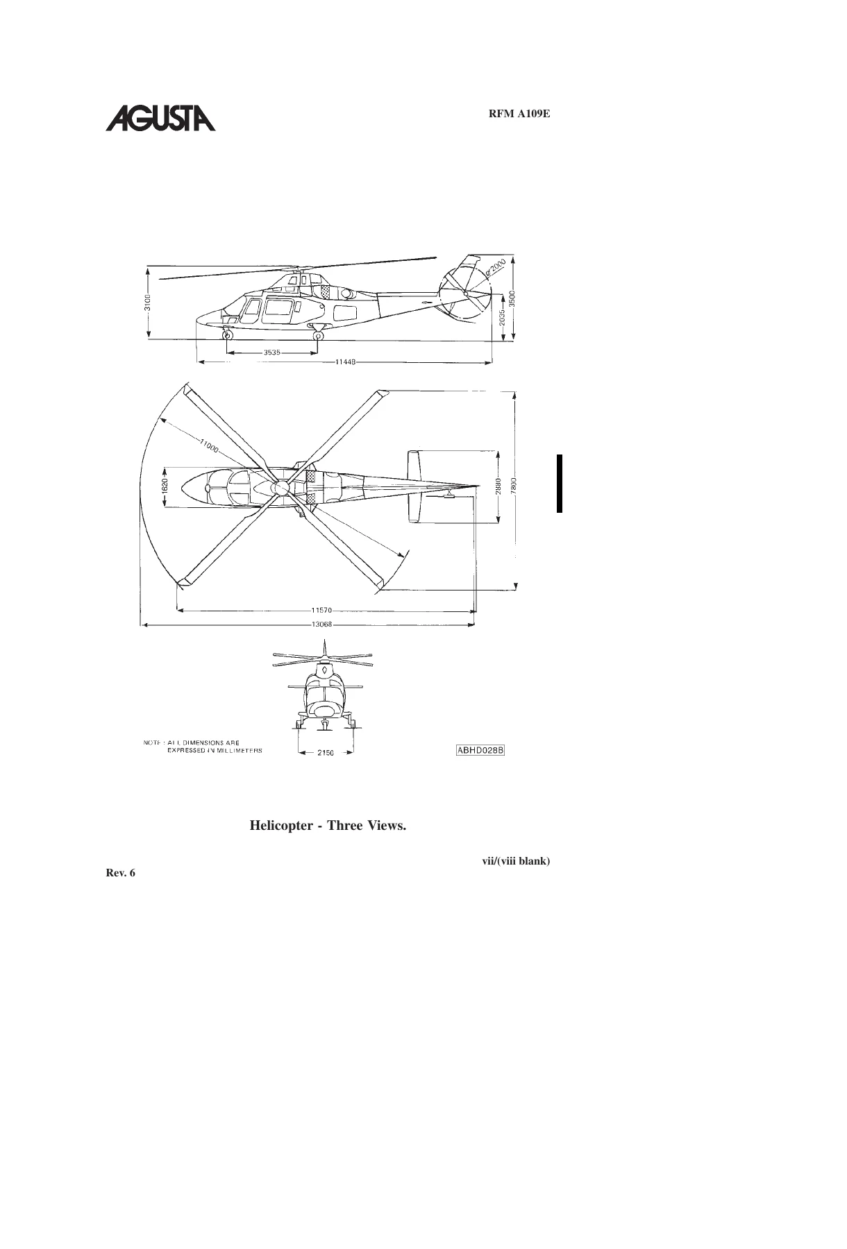
Part II contains manufacturer data. Weight and balance coverage includes datum-line locations, weights, arms and moments, longitudinal moments, lateral arms, loading computation, sample longitudinal and lateral loading calculations, weight-and-balance determination, helicopter weighing, and the use of charts and forms. The Systems Description section explains the A109E airframe arrangement and principal dimensions and then develops the main aircraft systems, including the cockpit panels and console, power plant, engine oil, fuel, flight controls, hydraulic systems, DC and AC electrical systems, Helipilot and Flight Director functions, and the Integrated Display System. Handling and servicing adds towing, taxiing, parking, mooring and servicing information.

Optional Equipment, Appendices and Supplements

This 1021-page A109E rotorcraft manual compilation contains an extensive Section 5 for optional equipment. The appendix list runs through Appendix 44 and includes rotor brake, engine-compartment fire extinguishers, Bendix King RDR 2000 weather radar, pulsed chip detector, environmental control system, bleed-air heater, searchlights, supplementary fuel tanks, EMS and emergency medical transportation configurations, sliding doors, equivalent Category A operations and training procedures, alternate Integrated Display System and EFIS configurations, GPS equipment, snow skid, emergency floats, wire-strike protection, external hoist, Skywatch traffic advisory equipment, Skyforce moving-map systems, satellite telephone, particle-separator engine-air-induction system, HF system, cargo hooks and other listed installations. The manual also contains a supplements list with aircraft-applicability information for items such as FLIR LEO II A-3, Homing DF931-05, rappelling installation, V/UHF AM-FM Flexcomm II and TELIT SAT550 telephone system.

The optional-equipment section is particularly important because installed equipment can change limitations, procedures, performance or configuration data. The manual itself directs the pilot to the pertinent appendices and supplements for equipment installed on the helicopter, and it includes an incompatibility table identifying combinations of optional installations that are not used together.

Chapters Covered

  • Introduction
    • General operating responsibility, terminology, warnings, cautions, notes and abbreviations
  • Section 1 – Limitations
    • Certification and type of operation; VFR/IFR requirements; flight crew and seating
    • Airspeed, ground speed, weight, CG, baggage, altitude and temperature limitations
    • Powerplant, N1/N2, TOT, rotor, transmission and torque limits
    • Fuel, engine oil, transmission oil and tail-rotor gearbox lubricant limits
    • Starter, generator, hydraulic-system and fluid-pressure limits
    • Instrument markings, EDU formats and placards
  • Section 2 – Normal Procedures
    • Flight planning, takeoff/landing and weight-and-balance preparation
    • Daily and every-flight preflight inspections
    • Engine pre-start, normal start, quick start, false start and dry motoring
    • Systems checks, taxiing, hover and rolling takeoffs
    • In-flight and Flight Director operation
    • Approach, landing, shutdown and post-flight checks
  • Section 3 – Emergency and Malfunction Procedures
    • Warning/caution system, EDU messages and aural warnings
    • One-engine and two-engine failures, hot start and in-flight restart
    • ECU faults and manual engine-control procedures
    • Tail-rotor, servo-hydraulic and landing-gear malfunctions
    • Electrical generator, bus, inverter and AC-system failures
    • Helipilot, Autotrim, intercommunication and IDS failures
    • Engine fire, smoke/toxic fumes, static-port obstruction and lightning
    • Emergency limit-override operation

    IMAGES PREVIEW

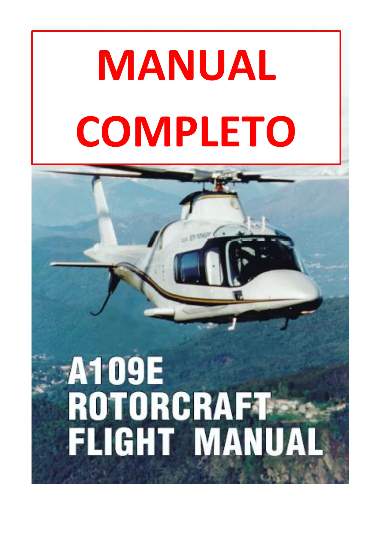
    Agusta A109E Rotorcraft Flight Manual with Supplements - PW206C PDF — PDF page 1 preview
    Agusta A109E Rotorcraft Flight Manual with Supplements - PW206C PDF — PDF page 38 preview
    Agusta A109E Rotorcraft Flight Manual with Supplements - PW206C PDF — PDF page 107 preview

  • Section 4 – Performance
    • Power assurance, density altitude and conversion charts
    • Allowable-wind envelopes and IGE/OGE hovering ceilings
    • Height-velocity diagrams
    • AEO and OEI rate-of-climb charts
    • Airspeed calibration
  • Section 5 – Optional Equipment
    • Optional-equipment appendices 1 through 44
    • Equipment incompatibility information and listed supplements
  • Section 6 – Weight and Balance
    • Datum locations, arms, moments and loading computations
    • Loading examples, weighing procedures, charts and forms
  • Section 7 – Systems Description
    • Helicopter description and principal dimensions
    • Powerplant, oil, fuel, flight control and hydraulic systems
    • DC/AC electrical systems
    • Helipilot, Flight Director and Integrated Display System
  • Section 8 – Handling and Servicing
    • Towing, taxiing, parking, mooring and servicing
  • Section 9 – Supplemental Performance Information
    • Helicopter configuration, cruise charts and OEI hovering-ceiling data

Taken as a whole, the manual gives A109E flight crews and operators a structured reference for operating boundaries, normal flight sequences, abnormal indications and responses, performance planning, loading calculations, aircraft-system understanding and configuration-dependent procedures. The combination of core RFM material, manufacturer data, charts and numerous equipment appendices makes it especially useful when a single reference is needed to check how an installed configuration affects operation.

Key A109E Data Found in the Manual

The manual states a maximum gross weight for takeoff and landing of 2850 kg (6283 lb) and a minimum gross weight for flight of 1850 kg (4078 lb). Maximum pressure altitude for takeoff and landing is listed as 15000 ft (4572 m), with maximum operating pressure altitude of 20000 ft (6096 m). The baggage compartment maximum load is 150 kg (330 lb). For the PW206C installation, the manual provides N1, N2, TOT, rotor-speed and torque limits as well as approved fuels and lubrication information. These values sit alongside the performance charts and system indications needed to apply them in operation.

Practical PDF Reference for A109E Operations

The Agusta A109E Rotorcraft Flight Manual with Supplements – PW206C PDF supports real operational tasks such as preparing the helicopter for flight, checking limitations, carrying out preflight and engine-start sequences, planning weight and balance, consulting performance charts, interpreting warning and caution indications, responding to engine or system malfunctions, and checking procedures for installed optional equipment. Correct limitations, procedures and configuration-specific data matter when decisions depend on exact speeds, weights, pressures, temperatures, power settings or system status. This manual is delivered as an instant PDF download after purchase – there is no physical shipping – so it can be kept on a computer, tablet or phone and printed when a paper reference is preferred.
Reviews

There are no reviews yet.

Be the first to review “Agusta A109E Rotorcraft Flight Manual with Supplements – PW206C PDF”

What Our Customers Say

★★★★★ Live reviews from customers
Loading customer reviews...
0
    0
    Your Cart
    Your cart is emptyReturn to Shop
    🛒
    Recently Purchased
    🕒 verified order