★ TRUSTED BY 321,897+ PROFESSIONALS WORLDWIDE
🏒
Trusted Business
Verified & Licensed
πŸ›‘οΈ
Virus Free Files
100% Safe Downloads
πŸ”’
Secure Payment
SSL Protected
⚑
Instant Delivery
Available Immediately
Sale!

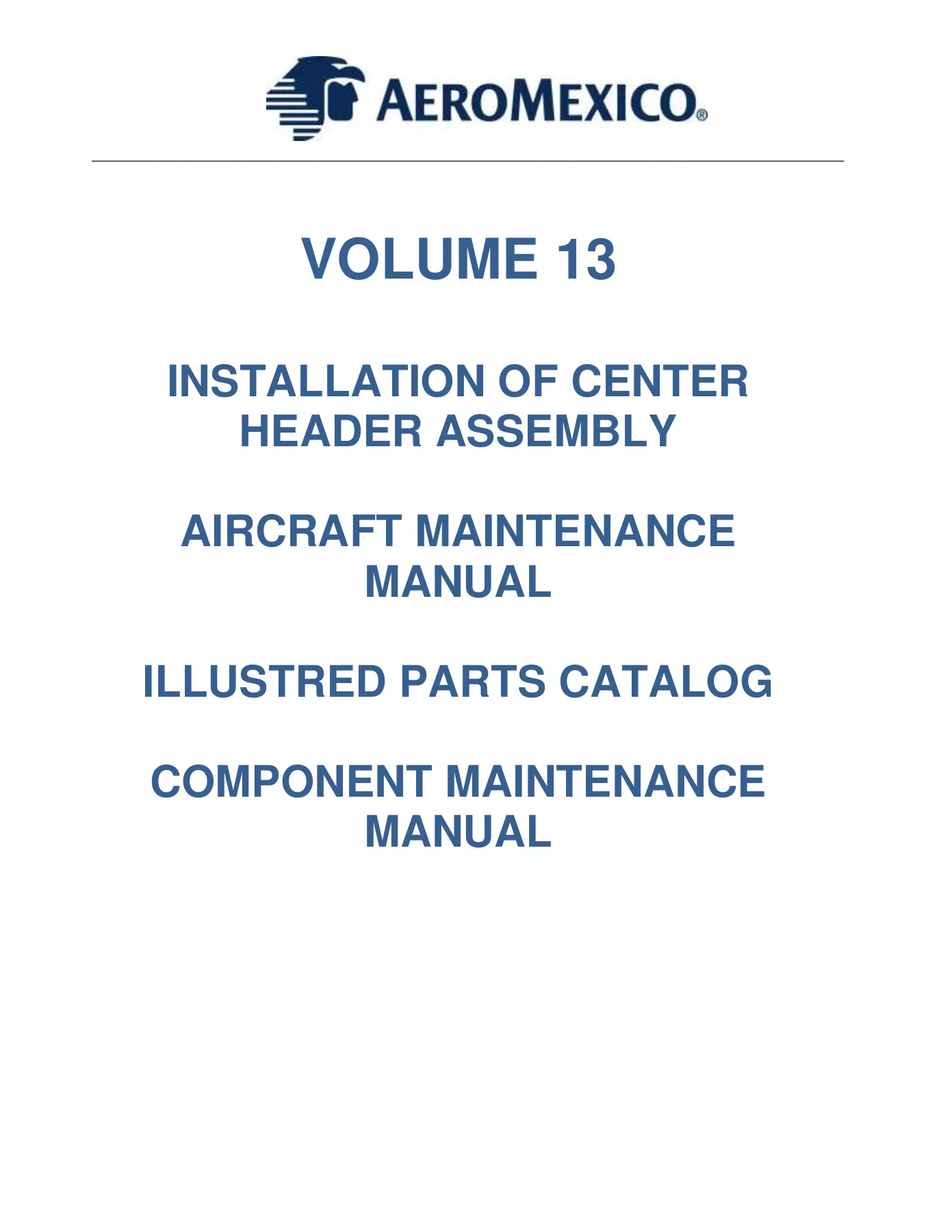
Boeing 737-800 & 737-8 MAX eX1 Center Header Assembly Maintenance Manual Supplement Volume 13

Original price was: $44.95.Current price is: $27.95.

Complete Volume 13 AMM supplement for Boeing 737-800 and 737-8 MAX covering eX1 Center Header Assembly installation and removal, Class Divider Assembly, Illustrated Parts Catalog, Component Maintenance Manual, Panasonic eX1 System documentation, and Fault Isolation Manual. Instant PDF download.

⚑
Instant PDF Download
Available immediately
πŸ’Ύ
Save to Your Device
Download & keep forever
πŸ›‘οΈ
Antivirus Scanned
100% virus-free
🌍
Trusted Worldwide
175,000+ customers

Description

Boeing 737 eX1 Center Header Assembly Maintenance Manual Supplement Volume 13

This is the complete Volume 13 supplement for the Boeing 737-800 and 737-8 MAX aircraft, covering the installation and removal of the eX1 Center Header Assembly. It brings together the Aircraft Maintenance Manual supplement, Illustrated Parts Catalog, Component Maintenance Manual, and the related Panasonic eX1 System documentation into one comprehensive reference for technicians working on cabin interior reconfiguration.

File Details

  • Manual Type: Aircraft Maintenance Manual Supplement, Illustrated Parts Catalog, Component Maintenance Manual
  • Brand: Boeing
  • Models Covered: Boeing 737-800, Boeing 737-8 MAX
  • Language: English
  • Page Count: Approximately 2,200 pages
  • File Format: PDF
  • Document Number: 110701R25-AMM
  • Revision: NC (Initial Release)
  • Revision Date: December 4, 2022

Chapters Covered

  • Introduction & Scope
    • Purpose & Applicability
    • Required Documents
    • Reference Documents
    • Airplane Effectiveness Identification
    • How to Use This Manual
    • Revision Service and Distribution
  • Center Header Assembly – Installation (Task 25-20-82-400-01)
    • General & References
    • Location Zones
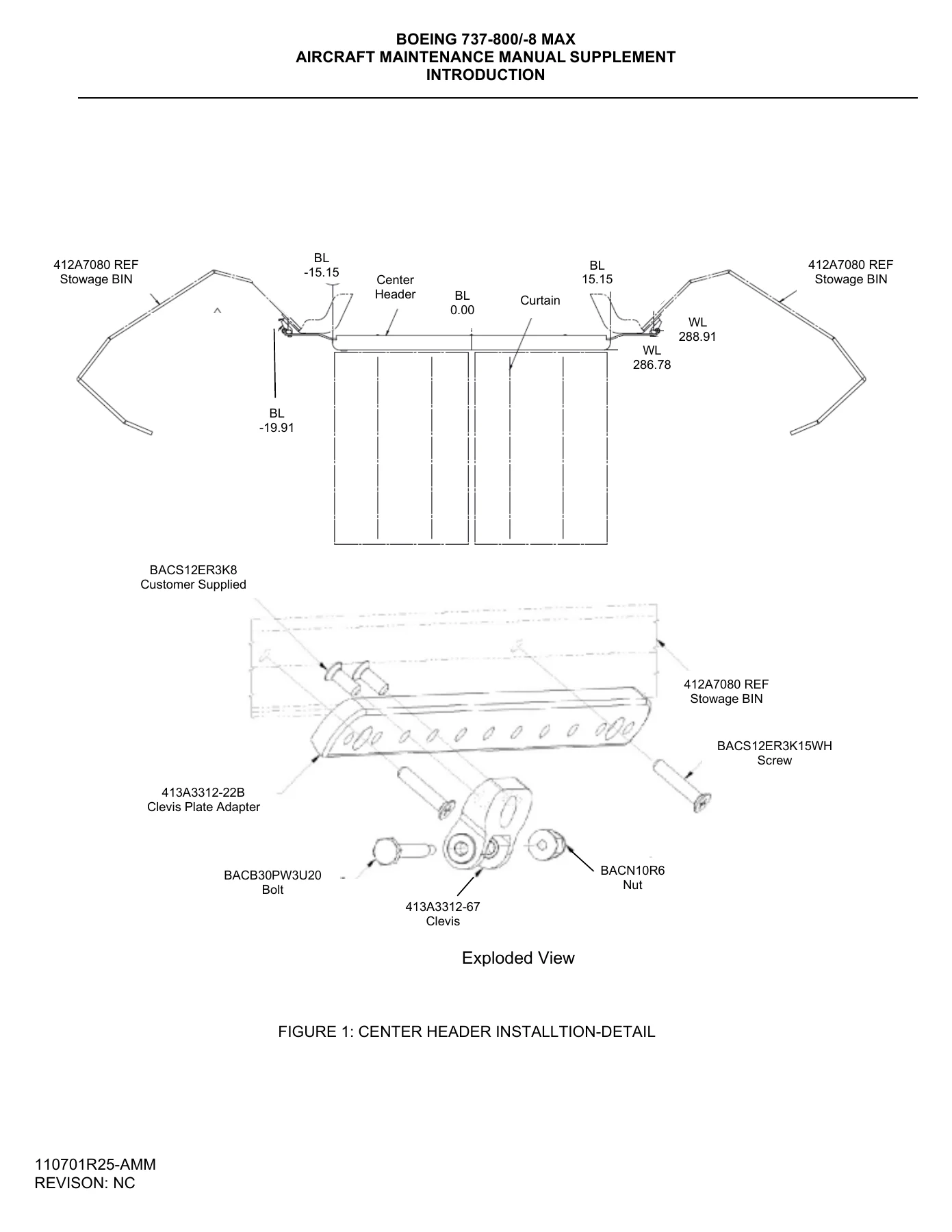
    • Clevis Plate Adapter & Clevis Installation
    • Header Assembly Attachment
    • Curtain Installation into Center Header
  • Center Header Assembly – Removal (Task 25-20-82-500-01)
    • General & References
    • Bolt and Nut Removal
    • Curtain Removal
  • Class Divider Assembly – Installation (Task 25-20-81-400-01)
    • Outboard and Inboard Clamp Installation
    • Structural Panel & Slotted Plate Installation
    • Curtain Track Installation
    • Curtain Installation
  • Class Divider Assembly – Removal (Task 25-20-81-500-01)
    • Curtain Track Plug Removal
    • Curtain Track Removal
    • Cover Panel Removal
    • Structural Panel Removal
    • Clamp Removal
  • Illustrated Parts Catalog (Appendix D)
    • Center Header Assembly – P/N 110701-501
    • Class Divider Assembly – P/N 110801-501
    • Numerical Index
    • Detailed Parts List
  • Component Maintenance Manual
    • Introduction & General Information
    • Description and Operation
    • Testing and Fault Isolation
    • Disassembly, Cleaning, Inspection, Repair
    • Assembly, Fits and Clearances
    • Special Tools & Equipment
    • Illustrated Parts List
    • Servicing & Storage
  • Panasonic eX1 System AMM Supplement
    • Introduction & Effectivity
    • Communications (Chapter 23)
    • Description and Operation
    • Maintenance Practices
    • Removal/Installation
    • Adjustment/Test
    • Inspection/Check
    • Cleaning/Painting
  • Panasonic eX1 System IPC
    • Detailed Parts List
    • Alpha/Numeric Index
    • Installation Figures
    • Maintenance Figures
  • Panasonic eX1 System Fault Isolation Manual Supplement
    • Master Fault Table
    • Observed Faults
    • Cabin BITE Faults
    • Fault Isolation Procedures
  • Delta Engineering Airplane Flight Manual Supplement
    • Panasonic Global Communication Suite
    • In-Flight Entertainment System
    • Certification Limitations
    • Non-Normal Procedures
    • Normal Procedures
  • Wiring Diagram Manual Content

This Volume 13 supplement gives maintenance technicians the complete procedure set for installing and removing the eX1 Center Header Assembly on Boeing 737-800 and 737-8 MAX aircraft. Beyond the core AMM tasks, it includes the Illustrated Parts Catalog for identifying every component by part number, the Component Maintenance Manual for bench-level work, and the Panasonic eX1 System documentation for the in-flight entertainment and communications equipment that integrates with the cabin interior.

The installation procedures walk through every step from locating the Clevis Plate Adapter and Clevis at the designated station to attaching the header assembly and fitting the curtain into the track. Removal procedures mirror the installation with clear bolt and nut identification. The Class Divider Assembly sections provide the same level of detail for the left and right dividers that create passenger seating zones.

Complete PDF Bookmark Tree

Complete Bookmarks

The complete bookmarks in the β€œBoeing 737-800 & 737-8 MAX eX1 Center Header Assembly Maintenance Manual Supplement Volume 13” are as follows:

ILLUSTRATED PARTS LISTp. 35
A. For an explanation of the component assembly order, refer to ASSEMBLY (Pageblock 7000) and to the Detailed Parts List indentation dot levels.p. 37
INTRODUCTIONp. 59
TASK 25-20-82-871-801-A01p. 59
TASK 25-20-82-879-801-A01p. 59
TASK 25-20-82-871-802-A01p. 59
TASK 25-20-82-871-803-A01p. 65
TASK 25-20-82-871-804-A01p. 66
TASK 25-20-82-871-805-A01p. 67
TASK 25-20-82-871-806-A01p. 67
TASK 25-20-82-871-807-A01p. 67
TASK 25-20-82-871-808-A01p. 67
TASK 25-20-82-871-809-A01p. 67
TASK 25-20-82-871-810-A01p. 68
DESCRIPTION AND OPERATIONp. 70
TASK 25-20-82-870-801-A01p. 70
TASK 25-20-82-870-803-A01p. 72
TASK 25-20-81-870-804-A01p. 72
TASK 25-20-82-870-805-A01p. 72
TESTING AND FAULT ISOLATIONp. 74
TASK 25-20-82-700-801-A01p. 74
TASK 25-20-82-700-94C-A01p. 74
TASK 25-20-82-700-801-A01p. 74
TASK 25-20-82-700-007-A01p. 74
TASK 25-20-82-700-801-A01p. 75
DISASSEMBLYp. 76
TASK 25-20-82-000-801-A01p. 76
CLEANINGp. 78
TASK 25-20-82-100-801-A01p. 78
D. Proceduresp. 79
SUBTASK 25-20-82-100-001-A01p. 79
SUBTASK 25-20-82-100-002-A01p. 79
SUBTASK 25-20-82-100-003-A01p. 79
INSPECTION/CHECKp. 80
TASK 25-20-82-200-801-A01p. 80
SUBTASK 25-20-82-200-210-A01p. 80
(1) Check the structure of the unit for scratches, cracks, holes and other damage.p. 80
(2) Joints.p. 80
(a) Check that all bolted joints of the components are satisfactorily attached. If necessary tighten loose screws or bolts. Refer to fits and clearances section 8000.p. 80
(3) Attachments.p. 80
(4) Placards.p. 80
REPAIRp. 82
TASK 25-20-82-300-801-A01p. 82
ASSEMBLYp. 86
TASK 25-20-82-400-801-A01p. 86
A. Assembly of the unit.p. 86
B. Generalp. 86
(a) Assemble the unit.p. 86
1 Refer to IPL Figure 1 to assemble Center Header Assemblyp. 86
FITS AND CLEARANCESp. 88
SPECIAL TOOLS, FIXTURES, EQUIPMENT AND CONSUMABLESp. 90
TASK 25-20-82-940-801-A01p. 90
ILLUSTRATED PARTS LISTp. 92
A. For an explanation of the component assembly order, refer to ASSEMBLY (Pageblock 7000) and to the Detailed Parts List indentation dot levels.p. 94
SERVICINGp. 100
TASK 25-20-81-610-801-A01p. 100
STORAGEp. 102
TASK 25-20-81-500-801-A01p. 102
ILLUSTRATED PARTS LISTp. 139
A. For an explanation of the component assembly order, refer to ASSEMBLY (Pageblock 7000) and to the Detailed Parts List indentation dot levels.p. 141
INTRODUCTIONp. 165
TASK 25-20-81-871-801-A01p. 165
TASK 25-20-81-879-801-A01p. 165
TASK 25-20-81-871-802-A01p. 165
TASK 25-20-81-871-803-A01p. 171
TASK 25-20-81-871-804-A01p. 172
TASK 25-20-81-871-805-A01p. 173
TASK 25-20-81-871-806-A01p. 173
TASK 25-20-81-871-807-A01p. 173
TASK 25-20-81-871-808-A01p. 173
TASK 25-20-81-871-809-A01p. 173
TASK 25-20-81-871-810-A01p. 174
DESCRIPTION AND OPERATIONp. 175
TASK 25-20-81-870-801-A01p. 175
TASK 25-20-81-870-803-A01p. 176
TASK 25-20-81-870-804-A01p. 177
TASK 25-20-81-870-805-A01p. 177
TASK 25-20-81-870-805-A01p. 178
TESTING AND FAULT ISOLATIONp. 181
TASK 25-20-81-700-801-A01p. 181
TASK 25-20-81-700-94C-A01p. 181
TASK 25-20-81-700-801-A01p. 181
TASK 25-20-81-700-007-A01p. 181
TASK 25-20-81-700-801-A01p. 182
DISASSEMBLYp. 183
TASK 25-20-81-000-801-A01p. 183
CLEANINGp. 185
TASK 25-20-81-100-801-A01p. 185
D. Proceduresp. 186
SUBTASK 25-20-81-100-001-A01p. 186
SUBTASK 25-20-81-100-002-A01p. 186
SUBTASK 25-20-81-100-003-A01p. 186
INSPECTION/CHECKp. 187
TASK 25-20-81-200-801-A01p. 187
SUBTASK 25-20-81-200-210-A01p. 187
(1) Check the structure of the unit for scratches, cracks, holes and other damage.p. 187
(2) Joints.p. 187
(a) Check that all bolted joints of the components are satisfactorily attached. If necessary tighten loose screws or bolts. Refer to fits and clearances section 8000.p. 187
(3) Attachments.p. 187
(4) Placards.p. 187
REPAIRp. 189
TASK 25-20-81-300-801-A01p. 189
ASSEMBLYp. 191
TASK 25-20-81-400-801-A01p. 191
A. Assembly of the unit.p. 191
B. Generalp. 191
(a) Assemble the unit.p. 191
1 Refer to IPL Figure 1 to assemble Class Divider Assemblyp. 191
FITS AND CLEARANCESp. 193
SPECIAL TOOLS, FIXTURES, EQUIPMENT AND CONSUMABLESp. 195
TASK 25-20-81-940-801-A01p. 195
ILLUSTRATED PARTS LISTp. 197
A. For an explanation of the component assembly order, refer to ASSEMBLY (Pageblock 7000) and to the Detailed Parts List indentation dot levels.p. 199
SERVICINGp. 207
TASK 25-20-81-610-801-A01p. 207
STORAGEp. 209
TASK 25-20-81-500-801-A01p. 209
FAA Approved: _________________________p. 212
Log of Revisionsp. 213
Introductionp. 215
Section 1 Certification Limitationsp. 216
Section 2 Non-Normal Proceduresp. 217
Section 3 Normal Proceduresp. 218
Section 4 Performancep. 219
1000307_AMM_AMX_B737_r17p. 220
TITLE PAGEp. 220
RECORD OF REVISIONSp. 222
HIGHLIGHTS OF REVISION 17p. 224
TRANSMITTAL LETTERp. 234
RECORD OF TEMPORARY REVISIONSp. 236
LIST OF CHAPTERSp. 238
INTRODUCTIONp. 240
1. Generalp. 240
2. Specification Conformancep. 240
3. Publication Informationp. 240
A. Major Sections of the Manualp. 240
4. Warnings, Cautions, and Notesp. 241
5. Effectivity Cross-Reference Tablep. 242
6. List of Abbreviationsp. 245
SERVICE BULLETIN LISTp. 250
TABLE OF CONTENTSp. 254
LIST OF EFFECTIVE PAGESp. 266
23-32-00 In-Flight Entertainment Systemp. 272
Description and Operationp. 272
1. Generalp. 272
A. In-Flight Entertainment System (IFES)p. 272
2. System Description (IFES)p. 273
A. Generalp. 273
B. IFESp. 273
3. User Interfaces with GUI Accessp. 276
A. Generalp. 276
B. Crew and Maintenance Interfacep. 276
C. Graphical User Interfacep. 276
4. Software Operationp. 277
A. Generalp. 277
B. Software Maintenance Proceduresp. 277
C. System Software Loadp. 278
D. Content Loadp. 279
E. Media Loadp. 279
F. Cross-Copyp. 280
G. Data Offloadp. 280
H. Software Cleanp. 280
5. Load Device Operationp. 282
A. Generalp. 282
B. PL100p. 282
C. PL500p. 282
D. PL1000/PL1000Rp. 282
E. PL1500p. 283
F. PL3000/PL3500p. 283
G. Hard Disk Drive – On-board Media Loader (HDD-OML)p. 283
H. Solid State Drive – On-board Media Loader (SSD-OML)p. 283
I. Secure Digital (SD) Cardsp. 283
J. USB Load Devicep. 284
K. External USB CD/DVD Drivep. 284
L. Typical Loader Usagep. 284
6. Power Supplyp. 285
A. Switchesp. 285
B. Power Distributionp. 285
7. Component Locationp. 289
A. Equipment Listp. 289
8. Component Descriptionp. 294
A. 10-inch Smart Monitor (SM) [DM DESC-CDE-0420 Rev. 1]p. 294
B. 10-inch Smart Monitor (SM) [DM DESC-CDE-0421 Rev. 1]p. 297
C. 10-inch Smart Monitor (SM) [DM DESC-CDE-0421 Rev. 1]p. 300
D. 11.1-inch Smart Monitor (SM) [DM DESC-CDE-0114 Rev. 2]p. 303
E. 13.3-inch Smart Monitor (SM) [DM DESC-CDE-0380 Rev. 4]p. 306
F. 3G Cell Modem (CM) [DM DESC-CDE-0387 Rev. 2]p. 309
G. 9-inch Smart Monitor (SM) [DM DESC-CDE-0059 Rev. 1]p. 313
H. 9-inch Smart Monitor (SM) [DM DESC-CDE-0085 Rev. 2]p. 315
I. Aircraft Interface (AI) [DM DESC-CDE-0139 Rev. 5]p. 318
J. Aircraft Interface (AI) [DM DESC-CDE-0140 Rev. 5]p. 322
K. Content Server (CS) [DM DESC-CDE-0152 Rev. 2]p. 326
L. Crew Panel (CP) [DM DESC-CDE-0159 Rev. 3]p. 329
M. Crew Terminal (CT) [DM DESC-CDE-0161 Rev. 5]p. 332
N. DC Seat Electronics Box (DC-SEB) [DM DESC-CDE-0165 Rev. 2]p. 335
O. DC Seat Electronics Box (DC-SEB) [DM DESC-CDE-0166 Rev. 4]p. 337
P. DC Zone Terminator (DC-ZT) [DM DESC-CDE-0410 Rev. 1]p. 339
Q. Enhanced Cell Modem (ECM) [DM DESC-CDE-0408 Rev. 2]p. 341
R. Handset [DM DESC-CDE-0185 Rev. 3]p. 344
S. Handset [DM DESC-CDE-0291 Rev. 14]p. 347
T. Hard Disk Drive – On-board Media Loader (HDD-OML) [DM DESC-CDE-0190 Rev. 3]p. 350
U. High Power Seat Box (HPS) [DM DESC-CDE-0518 Rev. 1]p. 353
V. In-seat Monitor Deployment Arm Assembly [DM DESC-CDE-0441 Rev. 1]p. 355
W. Integrated Server (IS) [DM DESC-CDE-0382 Rev. 2]p. 355
X. Remote Jack Module (RJM) [DM DESC-CDE-0252 Rev. 3]p. 359
Y. Solid State Drive – On-board Media Loader (SSD-OML) [DM DESC-CDE-0284 Rev. 6]p. 361
Z. Video Module/Passenger Service Unit (PSU) Panel Assembly [DM DESC-CDE-0318 Rev. 1]p. 364
Maintenance Practicesp. 368
TASK 23-32-00-860-801 Energize the In-Flight Entertainment Systemp. 368
TASK 23-32-00-860-802 De-energize the In-Flight Entertainment Systemp. 373
TASK 23-32-00-860-806 Log on to the Cabin Crew Screens with a Touchscreen Interfacep. 375
TASK 23-32-00-860-807 Log on to the Cabin Maintenance Screens with a Touchscreen Interfacep. 376
TASK 23-32-00-860-808 Log off from the Cabin Crew Screensp. 377
TASK 23-32-00-860-809 Connect and Start the Load Devicep. 378
TASK 23-32-00-860-810 Stop and Disconnect the Load Devicep. 381
Servicingp. 384
TASK 23-32-00-070-801 Clean Up Software, Media, and Contentp. 384
TASK 23-32-00-600-813 Set Flight Modep. 388
TASK 23-32-00-600-801 Configuration Checkp. 390
TASK 23-32-00-600-802 Data Offloadp. 396
TASK 23-32-00-600-803 LRU Port Readdressp. 401
TASK 23-32-00-600-805 Seat Resetp. 406
TASK 23-32-00-600-809 Set Air-to-Ground Modesp. 409
TASK 23-32-00-600-808 Review Fault Trendsp. 411
TASK 23-32-00-600-810 Review Flight Legsp. 415
TASK 23-32-00-600-811 Examine Reboot Logp. 419
TASK 23-32-00-616-810 Load Initial System/Core Softwarep. 422
TASK 23-32-00-616-803 Load Software with MAINT GUIp. 432
TASK 23-32-00-600-819 Load Media with MAINT GUIp. 441
TASK 23-32-00-600-840 Monitor Deployment Arm Assembly Adjustment Procedurep. 449
TASK 23-32-00-600-841 Replace Monitor Arm Mounting Screwsp. 450
TASK 23-32-00-600-816 Port Power Controlp. 453
TASK 23-32-00-600-835 Set Maintenance Aircraft Informationp. 458
TASK 23-32-00-600-836 Cell Modem Registrationp. 461
TASK 23-32-00-600-842 Examine Cell Modem Statusp. 463
TASK 23-32-00-600-856 Examine the Enhanced Cell Modem Statusp. 466
TASK 23-32-00-600-857 Factory Reset of Seat Componentsp. 469
TASK 23-32-00-600-843 RJ45 Port Configurationp. 472
TASK 23-32-00-600-823 Digital Overhead Monitor Readdressp. 474
TASK 23-32-00-600-844 Load Content with MAINT GUIp. 477
TASK 23-32-00-600-845 Examine NBD Load Statusp. 484
TASK 23-32-00-600-846 Configure Auto Offloadp. 487
TASK 23-32-00-600-837 Activate Mediap. 492
TASK 23-32-00-600-847 Review the Flight Statep. 495
TASK 23-32-00-600-850 Enable or Disable a Servicep. 498
TASK 23-32-00-600-838 Set Entertainment Modep. 500
TASK 23-32-00-600-839 Examine the Aircraft Discrete Listp. 502
TASK 23-32-00-600-848 Load Content on Crew Terminalp. 504
TASK 23-32-00-600-851 Examine the Content Reportp. 506
TASK 23-32-00-600-852 Examine the Media Reportp. 509
TASK 23-32-00-600-849 PED Power Controlp. 512
TASK 23-32-00-600-853 Remove Mediap. 516
TASK 23-32-00-600-854 Remove Contentp. 518
TASK 23-32-00-600-855 Seat Infop. 520
TASK 23-32-00-600-858 Load Software/Content via Engineering Loadp. 524
TASK 23-32-00-600-859 Unattended Media Loadp. 528
TASK 23-32-00-616-811 Load Daily Lite Mediap. 533
TASK 23-32-00-960-801 Replace Retainer Fastenersp. 535
TASK 23-32-00-960-802 Replace Spring Clips and Latch Platesp. 536
TASK 23-32-00-960-803 Replace Handset Cord Reelp. 539
TASK 23-32-00-960-804 Replace Nylatch Fastenersp. 542
TASK 23-32-00-960-805 Replace the Integrated Jack Unitp. 545
Removal/Installationp. 550
TASK 23-32-00-000-804 Remove Seat-to-Seat Cablesp. 550
TASK 23-32-00-400-804 Install Seat-to-Seat Cablesp. 553
TASK 23-32-00-400-805 Install the Cell Modem SIM Cardp. 558
TASK 23-32-00-000-805 Remove the In-Seat Harness Assemblyp. 560
TASK 23-32-00-400-806 Install the In-Seat Harness Assemblyp. 563
TASK 23-32-00-000-806 Remove the In-Arm Monitor Harness Assemblyp. 567
TASK 23-32-00-400-807 Install the In-Arm Monitor Harness Assemblyp. 570
Adjustment/Testp. 574
TASK 23-32-00-710-832 Passenger Service System Testp. 574
TASK 23-32-00-710-808 Operational Test of the In-Flight Entertainment Systemp. 576
TASK 23-32-00-710-828 Play a Video Test Sequencep. 579
TASK 23-32-00-710-825 In-Seat Video Testp. 581
TASK 23-32-00-710-801 Passenger Address and/or Boarding Media Systems Testp. 583
TASK 23-32-00-710-829 Cell Modem Testsp. 585
TASK 23-32-00-710-815 Enhanced Cell Modem Testp. 588
TASK 23-25-00-710-831 Video/Audio Monitoring Test for Wired and Wireless (Bluetooth) Headsetsp. 591
TASK 23-25-00-710-826 USB Device Testp. 594
TASK 23-25-00-710-812 Overhead Displays Power Control Testp. 596
TASK 23-25-00-710-833 Smoke Detection Alarm and System Shut-Off Testp. 598
TASK 23-25-00-710-834 Monitor the System During the Decompression Testp. 600
TASK 23-25-00-710-830 In-Seat Audio Testp. 602
TASK 23-25-00-740-801 Quick Test (BITE)p. 604
TASK 23-32-00-740-802 All Test (BITE)p. 608
TASK 23-32-00-820-801 Calibrate Control Panel Touchscreensp. 612
TASK 23-32-00-710-813 Bluetooth Audio Testp. 613
TASK 23-32-00-710-814 Bluetooth Audio Controlp. 615
Inspection/Checkp. 618
TASK 23-32-00-200-801 Check the Status of the Contentp. 618
TASK 23-32-00-210-802 Aircraft Wiring Inspectionp. 621
TASK 23-32-00-210-803 Component Inspectionp. 627
Cleaning/Paintingp. 638
TASK 23-32-00-100-802 Clean Component and Partsp. 638
23-32-06 Cell Modemp. 648
Removal/Installationp. 648
TASK 23-32-06-000-801 Remove the Cell Modemp. 648
TASK 23-32-06-400-801 Install the Cell Modemp. 658
TASK 23-32-06-000-802 Remove the Cell Modem Antennap. 664
TASK 23-32-06-400-802 Install the Cell Modem Antennap. 681
23-32-07 Seat Electronics Boxp. 688
Removal/Installationp. 688
TASK 23-32-07-000-801 Remove the Seat Electronics Boxp. 688
TASK 23-32-07-400-801 Install the Seat Electronics Boxp. 696
23-32-08 Seat Display Unit (Seatback)p. 702
Removal/Installationp. 702
TASK 23-32-08-000-801 Remove the Seat Display Unit (Seatback)p. 702
TASK 23-32-08-400-801 Install the Seat Display Unit (Seatback)p. 713
23-32-10 Overhead Display Unitp. 720
Removal/Installationp. 720
TASK 23-32-10-000-801 Remove the Overhead Display Unitp. 720
TASK 23-32-10-400-801 Install the Overhead Display Unitp. 724
23-32-14 Seat Display Unit (In-arm/Wall-mounted/Console-mounted)p. 728
Removal/Installationp. 728
TASK 23-32-14-000-801 Remove the Seat Display Unit (In-arm/Wall-mounted/Console-mounted)p. 728
TASK 23-32-14-400-801 Install the Seat Display Unit (In-arm/Wall-mounted/Console-mounted)p. 739
23-32-26 On-board Media Loaderp. 746
Removal/Installationp. 746
TASK 23-32-26-000-801 Remove the On-board Media Loaderp. 746
TASK 23-32-26-400-801 Install the On-board Media Loaderp. 760
23-32-29 Content Serverp. 768
Removal/Installationp. 768
TASK 23-32-29-000-802 Remove the Content Serverp. 768
TASK 23-32-29-400-802 Install the Content Serverp. 774
23-32-30 Crew Terminalp. 780
Removal/Installationp. 780
TASK 23-32-30-000-802 Remove the Crew Terminalp. 780
TASK 23-32-30-400-802 Install the Crew Terminalp. 785
TASK 23-32-30-000-801 Remove the Crew Panelp. 789
TASK 23-32-30-400-801 Install the Crew Panelp. 793
23-32-46 Integrated Serverp. 798
Removal/Installationp. 798
TASK 23-32-46-000-801 Remove the Integrated Serverp. 798
TASK 23-32-46-400-801 Install the Integrated Serverp. 803
23-32-48 Remote Jack Modulep. 808
Removal/Installationp. 808
TASK 23-32-48-000-805 Remove the Remote Jack Modulep. 808
TASK 23-32-48-400-805 Install the Remote Jack Modulep. 811
23-32-50 Handsetp. 814
Removal/Installationp. 814
TASK 23-32-50-000-801 Remove the Handsetp. 814
TASK 23-32-50-400-801 Install the Handsetp. 819
TASK 23-32-50-000-802 Remove the Handset Cradlep. 824
TASK 23-32-50-400-802 Install the Handset Cradlep. 829
23-32-52 Aircraft Interfacep. 834
Removal/Installationp. 834
TASK 23-32-52-000-801 Remove the Aircraft Interfacep. 834
TASK 23-32-52-400-801 Install the Aircraft Interfacep. 841
23-34-00 In-Flight Entertainment System (Audio)p. 846
Description and Operationp. 846
1. Component Descriptionp. 846
A. Remote Jack Module (RJM)p. 846
B. Remote Jack Unit (RJU)p. 848
23-34-10 Audio Jackp. 850
Removal/Installationp. 850
TASK 23-34-10-000-801 Remove the Audio Jackp. 850
TASK 23-34-10-400-801 Install the Audio Jackp. 856
23-81-00 In-Seat Power Supply Systemp. 860
Description and Operationp. 860
1. System Description (ISPSS)p. 860
A. Generalp. 860
B. ISPSSp. 860
2. Power Supplyp. 862
A. Switchesp. 862
3. Component Locationp. 863
A. Equipment Listp. 863
4. Component Descriptionp. 865
A. AC Outlet Unit (OU)p. 865
B. AC Outlet Unit (OU) with USBp. 867
C. Advanced Master Control Unit (AMCU)p. 869
D. Configuration Modulep. 873
E. In-Use Light (IUL)p. 875
F. Seat Power Module (SPM)p. 877
G. Seat Power Module (SPM)p. 880
Maintenance Practicesp. 884
TASK 23-81-00-860-801 Energize the In-Seat Power Supply Systemp. 884
TASK 23-81-00-860-802 De-energize the In-Seat Power Supply Systemp. 888
Adjustment/Testp. 890
TASK 23-81-00-710-801 Operational Test of the In-Seat Power Supply Systemp. 890
23-81-01 Power supply Unit/Configuration Modulep. 892
Removal/Installationp. 892
TASK 23-81-01-000-801 Remove the Advanced Master Control Unitp. 892
TASK 23-81-01-400-801 Install the Advanced Master Control Unitp. 899
TASK 23-81-01-000-802 Remove the Configuration Modulep. 904
TASK 23-81-01-400-802 Install the Configuration Modulep. 912
23-81-04 Power supply Unit/In-Use Lightp. 918
Removal/Installationp. 918
TASK 23-81-04-000-801 Remove the Power Outlet Unitp. 918
TASK 23-81-04-400-801 Install the Power Outlet Unitp. 924
TASK 23-81-04-000-802 Remove the In-Use Lightp. 929
TASK 23-81-04-400-802 Install the In-Use Lightp. 935
23-81-08 Seat Power Modulep. 940
Removal/Installationp. 940
TASK 23-81-08-000-801 Remove the Seat Power Modulep. 940
TASK 23-81-08-400-801 Install the Seat Power Modulep. 945
HIGHLIGHTS OF REVISION NO.15p. 949
TITLE PAGEp. 963
RECORD OF REVISIONSp. 965
RECORD OF TEMPORARY REVISIONSp. 967
LIST OF CHAPTERSp. 969
TABLE OF CONTENTSp. 971
LIST OF EFFECTIVE PAGESp. 989
INTRODUCTIONp. 1001
A. Generalp. 1001
B. Specification Conformancep. 1001
C. Publication Informationp. 1001
(1) Major Sectionsp. 1001
(2) Detailed Parts Listp. 1002
D. How to Identify Partsp. 1004
E. Revision Servicep. 1004
F. Revision Identificationp. 1004
G. List of Abbreviationsp. 1004
EFFECTIVITY CROSS-REFERENCE TABLEp. 1009
VENDOR LISTp. 1013
SERVICE BULLETIN LISTp. 1015
ALPHA/NUMERIC INDEXp. 1017
DETAILED PARTS LISTp. 1059
23-32-00 In-Flight Entertainment Systemp. 1060
Figure 1. Structural Instl, eX1 – Zone 220, 230p. 1060
Figure 2. Structural Instl, eX1 – Zone 120p. 1066
Figure 2A. Structural Instl, eX1 – Zone 120p. 1076
Figure 2B. Structural Instl, eX1 – Zone 110, 120p. 1086
Figure 3. Structural Instl, eX1 – Zone 210, 220p. 1094
Figure 3A. Structural Instl, eX1 – Zone 210, 220p. 1100
Figure 3B. Structural Instl, eX1 – Zone 210, 220p. 1108
Figure 4. Structural Instl, eX1 – Zone 230p. 1116
Figure 4A. Structural Instl, eX1 – Zone 230p. 1126
Figure 4B. Structural Instl, eX1 – Zone 230p. 1138
Figure 5. Structural Instl, eX1 – Zone 240p. 1148
Figure 5A. Structural Instl, eX1 – Zone 240p. 1156
Figure 6. Wiring Instl, eX1 – Zone 200p. 1164
Figure 6A. Wiring Instl, eX1 – Zone 200p. 1170
Figure 6B. Wiring Instl, eX1 – Zone 200p. 1176
Figure 7. P6-1 Panel, Structural Instl – Zone 210p. 1182
Figure 8. P6 Relay, Structural Instl – Zone 210p. 1186
Figure 9. eX1 Wiring Instl – Zone 100, 200p. 1188
Figure 9A. eX1 Wiring Instl – Zone 100, 200p. 1192
Figure 9B. eX1 Wiring Instl – Zone 100, 200p. 1196
Figure 9C. eX1 Wiring Instl – Zone 100, 200p. 1200
Figure 10. eX1 Wiring Instl – Zone 100, 200p. 1204
Figure 11. Structural Instl, eX1 – Zone 220p. 1220
Figure 11A. Structural Instl, eX1 – Zone 220p. 1226
Figure 12. Structural Instl, eX1 – Zone 230p. 1232
Figure 13. Structural Instl, eX1 – Zone 230p. 1236
Figure 14. Structural Instl, eX1 – Zone 240p. 1240
Figure 15. Structural Instl, eX1 – Zone 140p. 1244
Figure 16. Structural Instl, eX1 – Zone 230p. 1248
23-32-06 Cell Modemp. 1252
Figure 1. 3G Cell Modem (CM), Equipment Instl, – Zone 240p. 1252
Figure 1A. 3G Cell Modem (CM), Equipment Instl, – Zone 240p. 1254
Figure 2. Enhanced Cell Modem (ECM), Equipment Instl, – Zone 230p. 1256
Figure 3. CM Antenna Assembly, Equipment Instl, – Zone 230p. 1260
Figure 4. Wi-Fi Antenna Assembly, Equipment Instl, – Zone 230p. 1264
Figure 5. Enhanced Cell Modem (ECM), Equipment Instl – Zone 230p. 1268
Figure 5A. Enhanced Cell Modem (ECM), Equipment Instl – Zone 230p. 1272
Figure 5B. Enhanced Cell Modem (ECM), Equipment Instl – Zone 230p. 1276
Figure 6. CM Antenna Assembly, Equipment Instl – Zone 230p. 1278
Figure 6A. CM Antenna Assembly, Equipment Instl – Zone 230p. 1282
Figure 6B. CM Antenna Assembly, Equipment Instl – Zone 200p. 1286
Figure 7. Wi-Fi Antenna Assembly, Equipment Instl – Zone 230p. 1290
Figure 7A. Wi-Fi Antenna Assembly, Equipment Instl – Zone 230p. 1294
Figure 7B. Wi-Fi Antenna Assembly, Equipment Instl – Zone 200p. 1298
Figure 8. Enhanced Cell Modem (ECM), Equipment Instl – Zone 240p. 1300
Figure 9. CM Antenna Assembly, Equipment Instl – Zone 240p. 1304
Figure 10. Wi-Fi Antenna Assembly, Equipment Instl – Zone 240p. 1306
Figure 50. 3G Cell Modem (CM)p. 1308
Figure 51. 3G Cell Modem (CM)p. 1314
Figure 52. CM Antenna Assemblyp. 1320
Figure 53. Wi-Fi Antenna Assemblyp. 1324
23-32-07 Seat Electronics Boxp. 1328
Figure 1. DC Seat Electronics Box (DC-SEB), Seat Instl, Business Class – Zone 230p. 1328
Figure 1A. DC Seat Electronics Box (DC-SEB), Seat Instl, Business Class – Zone 230p. 1332
Figure 1B. DC Seat Electronics Box (DC-SEB), Seat Instl, Business Class – Zone 230p. 1336
Figure 1C. DC Seat Electronics Box (DC-SEB), Seat Instl, Business Class – Zone 230p. 1340
Figure 1D. DC Seat Electronics Box (DC-SEB), Seat Instl, Business Class – Zone 230p. 1346
Figure 2. DC Seat Electronics Box (DC-SEB), Seat Instl, Economy Class – Zone 230, 240p. 1352
Figure 2A. DC Seat Electronics Box (DC-SEB), Seat Instl, Economy Class – Zone 230, 240p. 1358
Figure 3. DC Zone Terminator (DC-ZT), Seat Instl, Business Class – Zone 230p. 1366
Figure 4. DC Seat Electronics Box (DC-SEB), Seat Instl, Business Class – Zone 230p. 1368
Figure 5. DC Seat Electronics Box (DC-SEB), Seat Instl, Economy Class – Zone 230, 240p. 1370
Figure 6. High Power Seat Box (HPS), Seat Instl, Economy Class – Zone 230, 240p. 1384
Figure 50. DC Seat Electronics Box (DC-SEB)p. 1394
Figure 51. DC Zone Terminator (DC-ZT)p. 1398
Figure 52. DC Seat Electronics Box (DC-SEB)p. 1402
Figure 53. High Power Seat Box (HPS)p. 1406
23-32-08 Seat Display Unit (Seatback)p. 1410
Figure 1. 9-inch Smart Monitor (SM), Seat Instl, Economy Class – Zone 230, 240p. 1410
Figure 1A. 10-inch Smart Monitor (SM), Seat Instl, Economy Class – Zone 230, 240p. 1414
Figure 1B. 10-inch Smart Monitor (SM), Seat Instl, Economy Class – Zone 230, 240p. 1418
Figure 1C. 10-inch Smart Monitor (SM), Seat Instl, Economy Class – Zone 230, 240p. 1420
Figure 2. 11.1-inch Smart Monitor (SM), Seat Instl, Business Class – Zone 230p. 1422
Figure 2A. 13.3-inch Smart Monitor (SM), Seat Instl, Business Class – Zone 230p. 1424
Figure 2B. 13.3-inch Smart Monitor (SM), Seat Instl, Business Class – Zone 230p. 1426
Figure 50. 9-inch Smart Monitor (SM)p. 1430
Figure 51. 11.1-inch Smart Monitor (SM)p. 1432
Figure 52. 10-inch Smart Monitor (SM)p. 1434
Figure 53. 13.3-inch Smart Monitor (SM)p. 1436
Figure 54. 10-inch Smart Monitor (SM)p. 1438
Figure 55. 10-inch Smart Monitor (SM)p. 1440
23-32-10 Overhead Display Unit (Wall-mounted/Retractable)p. 1442
Figure 1. Video Module Panel (Right), Equipment Instl – Zone 230p. 1442
Figure 2. Video Module Panel (Left), Equipment Instl – Zone 230p. 1444
Figure 50. Video Module Panel (Right)p. 1446
Figure 51. Video Module Panel (Left)p. 1450
23-32-14 Seat Display Unit (In-arm/Wall-mounted/Console-mounted)p. 1454
Figure 1. 9-inch Smart Monitor (SM) – In-arm, Seat Instl, Business Class – Zone 230p. 1454
Figure 2. 9-inch Smart Monitor (SM) – Wall-mounted, Seat Instl, Economy Class – Zone 230, 240p. 1458
Figure 2A. 10-inch Smart Monitor (SM) – Wall-mounted, Economy Class – Zone 230, 240p. 1462
Figure 2B. 10-inch Smart Monitor (SM) – Wall-mounted, Economy Class – Zone 230, 240p. 1470
Figure 3. 11.1-inch Smart Monitor (SM) – Wall-mounted, Seat Instl, Business Class – Zone 230p. 1474
Figure 3A. 13.3-inch Smart Monitor (SM) – Wall-mounted, Business Class – Zone 230p. 1480
23-32-26 On-board Media Loaderp. 1488
Figure 1. Hard Disk Drive – On-board Media Loader (HDD-OML), Equipment Instl – Zone 220p. 1488
Figure 1A. Hard Disk Drive – On-board Media Loader (HDD-OML), Equipment Instl – Zone 240p. 1492
Figure 1B. Hard Disk Drive – On-board Media Loader (HDD-OML), Equipment Instl, G7 Galley – Zone 220p. 1496
Figure 1C. Hard Disk Drive – On-board Media Loader (HDD-OML), Equipment Instl, G7 Galley – Zone 220p. 1500
Figure 1D. Solid State Drive – On-board Media Loader (SSD-OML), Equipment Instl, G7 Galley – Zone 220p. 1504
Figure 50. Hard Disk Drive – On-board Media Loader (HDD-OML)p. 1510
Figure 51. Solid State Drive – On-board Media Loader (SSD-OML)p. 1512
23-32-29 Media Server/Content Serverp. 1514
Figure 1. Content Server (CS), Equipment Instl, EE-Bay, E8-1 Shelf – Zone 110p. 1514
Figure 1A. Content Server (CS), Equipment Instl, EE-Bay, E4-1 Shelf – Zone 120p. 1518
Figure 1B. Content Server (CS), Equipment Instl, EE-Bay, E4-1 Shelf – Zone 120p. 1520
23-32-30 Control Panel (CMT/CT/CP)p. 1522
Figure 1. Crew Panel (CP), Equipment Instl, VCC – Zone 220p. 1522
Figure 1A. Crew Panel (CP), Equipment Instl, VCC – Zone 220p. 1526
Figure 1B. Crew Panel (CP), Equipment Instl, Emergency Stow Box – Zone 220p. 1530
Figure 2. Crew Terminal (CT), Equipment Instl, – Zone 220p. 1532
Figure 3. Crew Terminal (CT), Equipment Instl, – Zone 220p. 1536
Figure 4. RCC Assembly, Wall Mount Instl – Zone 220p. 1540
Figure 50. Crew Terminal (CT)p. 1544
Figure 51. Crew Panel (CP)p. 1546
23-32-46 Integrated Serverp. 1548
Figure 1. Integrated Server (IS), Equipment Instl, E6-1 Rack – Zone 140p. 1548
Figure 2. Integrated Server (IS), Equipment Instl – Zone 140p. 1552
23-32-48 Remote Jack Modulep. 1556
Figure 1. Remote Jack Module (RJM), Seat Instl, Business Class – Zone 230p. 1556
23-32-50 Passenger Control Unit/Handsetp. 1558
Figure 1. Handset, Seat Instl, Business Class – Zone 230p. 1558
Figure 1A. Handset, Seat Instl, Business Class – Zone 230p. 1560
Figure 1B. Handset, Seat Instl, Business Class – Zone 230p. 1562
Figure 50. Cradlep. 1566
Figure 51. Cradlep. 1570
23-32-52 Aircraft Interfacep. 1574
Figure 1. Aircraft Interface (AI), Equipment Instl, EE-Bay, E8-1 Shelf – Zone 110p. 1574
Figure 1A. Aircraft Interface (AI), Equipment Instl, EE-Bay, E4-1 Shelf – Zone 120p. 1576
Figure 1B. Aircraft Interface (AI), Equipment Instl, EE-Bay, E3-3 Shelf – Zone 120p. 1578
Figure 1C. Aircraft Interface (AI), Equipment Instl, EE-Bay, E8-1 Shelf – Zone 110, 120p. 1580
Figure 1D. Aircraft Interface (AI), Equipment Instl, EE-Bay, E8-1 Shelf – Zone 110p. 1582
23-32-55 Seat-to-seat Cablesp. 1584
Figure 1. Seat-to-seat Harnesses, Seat Wiring Instl – Zone 220, 230, 240p. 1584
Figure 1A. Seat-to-seat Harnesses, Seat Wiring Instl – Zone 230, 240p. 1592
Figure 1B. Seat-to-seat Harnesses, Seat Wiring Instl – Zone 200p. 1600
Figure 1C. Seat-to-seat Harnesses, Seat Wiring Instl – Zone 200p. 1606
Figure 1D. Seat-to-seat Harnesses, Seat Wiring Instl – Zone 200p. 1612
Figure 2. Seat-to-seat Harnesses, Seat Wiring Instl – Zone 220, 230, 240p. 1618
Figure 2A. Seat-to-seat Harnesses, Seat Wiring Instl – Zone 220, 230, 240p. 1626
Figure 2B. Seat-to-seat Harnesses, Seat Wiring Instl – Zone 220, 230, 240p. 1634
23-34-10 Audio Jackp. 1642
Figure 1. Remote Jack Unit (RJU), Seat Instl, Business Class – Zone 230p. 1642
Figure 1A. Remote Jack Module (RJM), Seat Instl, Business Class – Zone 230p. 1644
Figure 1B. Remote Jack Module (RJM), Seat Instl, Business Class – Zone 230p. 1646
Figure 2. Remote Jack Unit (RJU), Seat Instl, Economy Class – Zone 230, 240p. 1648
Figure 2A. Remote Jack Unit (RJU), Seat Instl, Economy Class – Zone 230, 240p. 1650
Figure 50. Remote Jack Unit (RJU)p. 1654
23-81-01 Power Supply Unitp. 1656
Figure 1. Advanced Master Control Unit (AMCU), Equipment Instl – Zone 230p. 1656
Figure 1A. Advanced Master Control Unit (AMCU), Equipment Instl – Zone 230p. 1660
Figure 1B. Advanced Master Control Unit (AMCU), Equipment Instl – Zone 230p. 1662
Figure 1C. Advanced Master Control Unit (AMCU), Equipment Instl – Zone 230p. 1664
Figure 2. Advanced Master Control Unit (AMCU), Equipment Instl – Zone 240p. 1668
Figure 2A. Advanced Master Control Unit (AMCU), Equipment Instl – Zone 240p. 1672
Figure 2B. Advanced Master Control Unit (AMCU), Equipment Instl – Zone 240p. 1674
Figure 3. AMCU Configuration Module, Equipment Instl – Zone 230p. 1678
Figure 3A. AMCU Configuration Module, Equipment Instl – Zone 230p. 1682
Figure 3B. AMCU Configuration Module, Equipment Instl – Zone 230p. 1684
Figure 3C. AMCU Configuration Module, Equipment Instl – Zone 230p. 1686
Figure 4. AMCU Configuration Module, Equipment Instl – Zone 240p. 1690
Figure 4A. AMCU Configuration Module, Equipment Instl – Zone 240p. 1694
Figure 4B. AMCU Configuration Module, Equipment Instl – Zone 240p. 1696
Figure 50. AMCU Configuration Modulep. 1698
23-81-04 Power Outlet Unit/In-use Lightp. 1702
Figure 1. In-use Light (IUL), Seat Instl, Business Class – Zone 230p. 1702
Figure 1A. In-use Light (IUL), Seat Instl, Business Class – Zone 230p. 1704
Figure 1B. In-use Light (IUL), Seat Instl, Business Class – Zone 230p. 1706
Figure 2. AC Outlet Unit (OU), Seat Instl, Business Class – Zone 230p. 1710
Figure 2A. AC Outlet Unit (OU), Seat Instl, Business Class – Zone 230p. 1712
Figure 2B. AC Outlet Unit (OU), Seat Instl, Business Class – Zone 230p. 1714
Figure 3. In-use Light (IUL), Seat Instl, Economy Class – Zone 230, 240p. 1716
Figure 4. AC Outlet Unit (OU), Seat Instl, Economy Class – Zone 230, 240p. 1720
23-81-08 Seat Power Modulep. 1724
Figure 1. Seat Power Module (SPM), Seat Instl, Business Class – Zone 230p. 1724
Figure 1A. Seat Power Module (SPM), Seat Instl, Business Class – Zone 230p. 1728
Figure 1B. Seat Power Module (SPM), Seat Instl, Business Class – Zone 230p. 1732
Figure 1C. Seat Power Module (SPM), Seat Instl, Business Class – Zone 230p. 1736
Figure 2. Seat Power Module (SPM), Seat Instl, Economy Class – Zone 230, 240p. 1742
Figure 2A. Seat Power Module (SPM), Seat Instl, Economy Class – Zone 230, 240p. 1746
Figure 2B. Seat Power Module (SPM), Seat Instl, Economy Class – Zone 230, 240p. 1752
Figure 50. Seat Power Module (SPM) – 400Wp. 1762
Figure 51. Seat Power Module (SPM) – 250Wp. 1766
3000333_FIM_AMX_B737_r1p. 1768
TITLE PAGEp. 1768
EFFECTIVITY CROSS-REFERENCE TABLEp. 1770
TRANSMITTAL LETTERp. 1774
HIGHLIGHTSp. 1776
RECORD OF REVISIONSp. 1784
RECORD OF TEMPORARY REVISIONSp. 1786
LIST OF CHAPTERSp. 1788
INTRODUCTIONp. 1790
1. Generalp. 1790
2. How to Use this Publicationp. 1790
A. Introductionp. 1790
B. Master Fault Tablep. 1790
C. Fault Isolation Proceduresp. 1790
3. Warnings, Cautions and Notesp. 1790
4. How to Isolate and Remedy a Faultp. 1790
A. Instructionsp. 1790
5. Observed Faultp. 1792
A. Observed Fault Reporting Methodsp. 1792
B. Observed Fault Codes Identifiersp. 1792
6. Special Tools, Fixtures, and Equipmentp. 1797
7. The list that follows identifies Cabin BITE Faults – Maintenance Message Number, ATA ID and MaintenanceMessage Descriptionp. 1798
8. List of Abbreviationsp. 1805
SERVICE BULLETIN LISTp. 1810
TABLE OF CONTENTSp. 1814
LIST OF EFFECTIVE PAGESp. 1820
23 – COMMUNICATIONSp. 1812
23-32 – PASSENGER ADDRESS, ENTERTAINMENT & COMFORTp. 1826
23-32-00 – PASSENGER ADDRESS, ENTERTAINMENT & COMFORTp. 1826
23-32-00- Fault Isolation Procedurep. 1826
23-32-00-811-801 – No Data from Handsetp. 1826
23-32-00-811-802 – No Data from AIMS-Lp. 1830
23-32-00-811-803 – No Data from AIMS-Rp. 1833
23-32-00-811-804 – No Data from FMCp. 1836
23-32-00-811-805 – No Data from ACARSp. 1839
23-32-00-811-806 – No Data from FMSp. 1842
23-32-00-811-807 – No Data from ADCp. 1845
23-32-00-811-808 – No Data from CPp. 1848
23-32-00-811-809 – Unable to Detect Touch Screen Calibration Datap. 1851
23-32-00-811-810 – No Data from SDUp. 1853
23-32-00-811-811 – SDU Backlight Failurep. 1856
23-32-00-811-812 – SDU Power to USB Port has been Disabled Due to a Shorted Conditionp. 1858
23-32-00-811-813 – SDU Touchscreen is Not Respondingp. 1863
23-32-00-811-814 – SDU Memory Failurep. 1866
23-32-00-811-937 – SDU Internal Memory Failurep. 1868
23-32-00-811-815 – SDU with an Invalid IP Addressp. 1870
23-32-00-811-816 – SDU Over Temperature Condition Detectedp. 1872
23-32-00-811-817 – SDU Input Power Supplied is Outside Normal Operating Rangep. 1875
23-32-00-811-818 – SDU Network Connection Failurep. 1878
23-32-00-811-819 – SDU Primary Network Path Interrupted – Redundant Path Activatedp. 1881
23-32-00-811-820 – SDU Critically High Temperature Condition Detectedp. 1883
23-32-00-811-821 – SDU Hard Drive Read Failurep. 1886
23-32-00-811-822 – Hard Disk Full No Space Leftp. 1888
23-32-00-811-823 – SDU Redundant Cable Installation Failedp. 1890
23-32-00-811-825 – No Data from MCUp. 1894
23-32-00-811-826 – MCU PED Port Power Disabledp. 1897
23-32-00-811-827 – MCU Port Power Phase A Failurep. 1900
23-32-00-811-828 – MCU Port Power Phase B Failurep. 1902
23-32-00-811-829 – MCU Port Power Phase C Failurep. 1904
23-32-00-811-830 – MCU GFI Trippedp. 1906
23-32-00-811-831 – MCU GFI Self Test Failedp. 1908
23-32-00-811-832 – MCU Port Overcurrent Phase Ap. 1910
23-32-00-811-833 – MCU Port Overcurrent Phase Bp. 1912
23-32-00-811-834 – MCU Port Overcurrent Phase Cp. 1914
23-32-00-811-835 – MCU Port Unavailablep. 1916
23-32-00-811-836 – No Data from Seatboxp. 1919
23-32-00-811-837 – SEB Probable Broken Wire to a Seat Columnp. 1922
23-32-00-811-838 – A Configured Seatbox is Not Detectedp. 1925
23-32-00-811-839 – ZTDC02 Primary Network Path Interrupted – Redundant Path Activatedp. 1928
23-32-00-811-840 – SEB Redundant Cable Installation Failedp. 1930
23-32-00-811-841 – Seatbox with an Invalid IP Addressp. 1933
23-32-00-811-842 – SEB Network Speed Degradedp. 1936
23-32-00-811-843 – Seatbox Quantity of SDUs Detected Differs from SDUs Configuredp. 1939
23-32-00-811-844 – SEB Input Power Supplied is Outside Normal Operating Rangep. 1942
23-32-00-811-845 – SEB Network Connection Failurep. 1945
23-32-00-811-846 – SEB Power to USB Port has been Disabled Due to a Shorted Conditionp. 1948
23-32-00-811-847 – Seatbox Internal Memory Failurep. 1953
23-32-00-811-939 – SEB Over-Temperature Condition Detectedp. 1955
23-32-00-811-940 – SEB Critically High Temperature Condition Detectedp. 1958
23-32-00-811-848 – No Data from AIp. 1961
23-32-00-811-849 – AI EE Rack Fan Failurep. 1964
23-32-00-811-850 – AI BITE FDMT Database is Not Installedp. 1966
23-32-00-811-851 – AI Usage of Compact Flash is Fullp. 1968
23-32-00-811-852 – AI One or More Payment Files has Not Successfully Offloadedp. 1970
23-32-00-811-853 – AI Internal Fault (429 Port Failure)p. 1972
23-32-00-811-854 – AI Internal Fault (485 Port Failure)p. 1974
23-32-00-811-855 – AI Media Decoding Errorp. 1976
23-32-00-811-856 – AI Network Connection Failurep. 1978
23-32-00-811-857 – Aircraft Bus Data to Populate ARINC 763 APS MIB is Invalid or Shows Errorsp. 1980
23-32-00-811-858 – MPDS link between AI and SDU/Bearer Indicates a Problemp. 1983
23-32-00-811-864 – Data3 Link Between AI and SDU/Bearer Indicates a Problemp. 1985
23-32-00-811-866 – AI Hard Drive Errorp. 1987
23-32-00-811-867 – AI Quantity of Seatboxes Detected Differs from Seatboxes Configuredp. 1989
23-32-00-811-868 – No Data from HC11 to AIp. 1992
23-32-00-811-869 – AI Over-Temperature Condition Detectedp. 1994
23-32-00-811-870 – AI Network Connection Failurep. 1997
23-32-00-811-871 – AI Network Speed Degradedp. 2000
23-32-00-811-872 – No Data from SPMp. 2003
23-32-00-811-873 – SPM Reports with Bootloader Component Onlyp. 2007
23-32-00-811-874 – SPM AS1 PS1 Failp. 2009
23-32-00-811-875 – SPM AST PS2 Failp. 2011
23-32-00-811-876 – SPM AST Current Limit Ap. 2013
23-32-00-811-877 – SPM AST Current Limit Bp. 2016
23-32-00-811-878 – SPM AST Current Limit Cp. 2019
23-32-00-811-879 – SPM AST Current Limit Dp. 2022
23-32-00-811-880 – SPM AST In Use A Failp. 2025
23-32-00-811-881 – SPM AST In Use B Failp. 2028
23-32-00-811-882 – SPM AST DC Tolerance Failp. 2031
23-32-00-811-883 – No Data from CTp. 2033
23-32-00-811-884 – CT Over-Temperature Condition Detectedp. 2036
23-32-00-811-885 – CT Backlight Failurep. 2039
23-32-00-811-886 – CT Input Power Supplied is Outside Normal Operating Rangep. 2041
23-32-00-811-887 – CT Network Connection Failurep. 2043
23-32-00-811-888 – CT Primary Network Path Interrupted – Redundant Path Activatedp. 2045
23-32-00-811-889 – CT Power to USB Port has been Disabled Due to a Shorted Conditionp. 2047
23-32-00-811-890 – CT Critically High Temperature Condition Detectedp. 2049
23-32-00-811-891 – CT Internal Memory Failurep. 2052
23-32-00-811-892 – CT Internal Memory Failurep. 2054
23-32-00-811-893 – CT Hard Drive Write Errorp. 2056
23-32-00-811-894 – CT Hard Drive Read Errorp. 2058
23-32-00-811-895 – CT Redundant Cable Installation Failedp. 2060
23-32-00-811-896 – No Data from DOMp. 2062
23-32-00-811-897 – No Data from Cell Modemp. 2065
23-32-00-811-898 – ECM Network Connection Failurep. 2069
23-32-00-811-899 – ECM Primary Network Path Interrupted – Redundant Path Activatedp. 2072
23-32-00-811-901 – ECM Internal Memory Failurep. 2075
23-32-00-811-902 – ECM Memory Failurep. 2077
23-32-00-811-903 – ECM Redundant Cable Installation Failedp. 2079
23-32-00-811-904 – No Data from OMLp. 2081
23-32-00-811-905 – No Data from CS (File Server) to AIp. 2085
23-32-00-811-906 – CS Over-Temperature Condition Detectedp. 2088
23-32-00-811-938 – CS (File Server) Fan Failurep. 2091
23-32-00-811-907 – CS BITE FDMT Database is Not Installedp. 2093
23-32-00-811-908 – CS (File Server) Flash Memory Failurep. 2095
23-32-00-811-909 – CS (File Server) Memory Failurep. 2097
23-32-00-811-910 – CS (File Server) Memory Failurep. 2099
23-32-00-811-911 – CS (File Server) Compact Flash Not Mountedp. 2101
23-32-00-811-912 – CS Memory Device is Not Mountedp. 2103
23-32-00-811-913 – A Software Application has Exceeded the Soft/Hard Limit of its Assigned Disk Spacep. 2105
23-32-00-811-914 – CS Quantity of Seatboxes Detected Differs from Seatboxes Configuredp. 2107
23-32-00-812-915 – CS Media Index Errorp. 2110
23-32-00-811-916 – CS (File Server) Hardware Sensor Failurep. 2112
23-32-00-811-917 – No Data from CS (Media Server)p. 2114
23-32-00-811-918 – CS (Media Server) Fan Failurep. 2117
23-32-00-811-919 – CS (Media Server) Reports that the Data Content is Not Identical on all DAsp. 2119
23-32-00-811-920 – CS (Media Server) Detects a Communication Failure to One of the Fiber Optic Portsp. 2122
23-32-00-811-921 – No Data from CS (Disk Array)p. 2124
23-32-00-811-922 – CS (Disk Array) Hard Drive Read Errorp. 2127
23-32-00-811-923 – CS (Disk Array) Hard Drive Errorp. 2129
23-32-00-811-924 – CS (Media Server) Detects a Communication Failure to One of the Fiber Optic Portsp. 2131
23-32-00-811-925 – No Data from ISp. 2133
23-32-00-811-941 – IS Hard Drive Read Errorp. 2137
23-32-00-811-927 – IS Memory Failurep. 2140
23-32-00-811-928 – IS Hard Drive Errorp. 2142
23-32-00-811-929 – IS One or More Payment Files has Not Successfully Offloadedp. 2144
23-32-00-811-930 – IS Media Index Errorp. 2146
23-32-00-811-931 – IS Network Connection Failurep. 2148
23-32-00-811-932 – IS Memory Device is Not Mountedp. 2151
23-32-00-811-933 – IS Quantity of LRUs Detected Differs from LRUs Configuredp. 2153
23-32-00-811-934 – No Data from IS_ARM_LIBp. 2156
23-32-00-811-935 – IS Primary Network Path Interrupted – Redundant Path Activatedp. 2159
23-32-00-811-936 – No Data from CSSCp. 2161
23-32-00-810-801 – PA Audio Malfunction in Entire Aircraftp. 2164
23-32-00-810-802 – LRU Power Failurep. 2166
23-32-00-810-803 – LRU Power Malfunction in CWS/VCCp. 2168
23-32-00-810-804 – LRU Power Malfunction in Cabin and Overheadp. 2171
23-32-00-810-805 – LRU Power Malfunction in EE-Bay/IFEC/CECp. 2174
23-32-00-810-806 – LRU Power Malfunction in RCCp. 2177
23-32-00-810-807 – Malfunction in Multiple Seat Groupsp. 2180
23-32-00-810-808 – No Communication/No Data Detected For an LRUp. 2183
23-32-00-810-809 – SDU Credit Card Reader (CCR) Malfunctionp. 2185
23-32-00-810-810 – AC OU Malfunctionp. 2187
MASTER FAULT TABLEp. 2192
OBSERVED FAULTS – SORTED BY OBSERVED FAULT DESCRIPTIONp. 2192
OBSERVED FAULTS – SORTED BY OBSERVED FAULT CODEp. 2192
CABIN BITE FAULTS – SORTED BY MAINTENANCE MESSAGE DESCRIPTIONp. 2193
CABIN BITE FAULTS – SORTED BY MAINTENANCE MESSAGE NUMBERp. 2201

What This Manual Enables You to Do

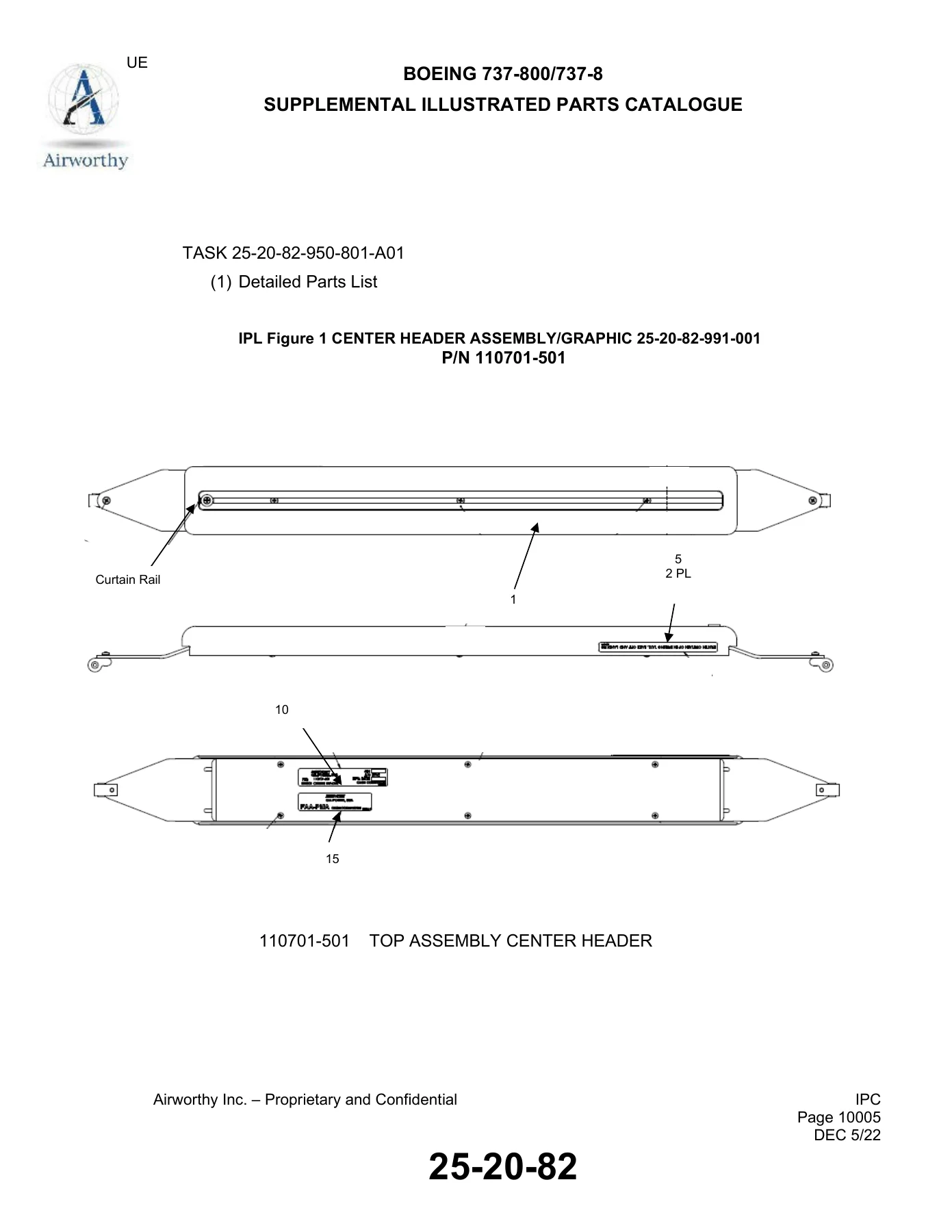
With this supplement in hand, you can perform the full installation or removal of the Center Header Assembly without guessing at hardware or torques. The Illustrated Parts Catalog lets you look up every part number for the header, curtain track, clevis, and attaching hardware. The Component Maintenance Manual covers cleaning, inspection, repair, and assembly of the header and divider units themselves. The Panasonic eX1 System sections add the communications and entertainment equipment documentation, and the Fault Isolation Manual helps you troubleshoot the IFE system when faults appear.

The procedures include specific part numbers for every screw, bolt, nut, washer, and clamp, so you order the right hardware the first time. Task numbering follows ATA iSpec 2200 conventions, making it easy to cross-reference with the base Boeing AMM. The effectiveness tables list every applicable aircraft by registration number, so you can confirm coverage before you start work.

Why This Manual Matters

Cabin interior reconfiguration work demands precision. The Center Header Assembly attaches to the Boeing Standard Upper Overhead Bin rail at two outboard attachment lugs, and the Class Divider mounts to the AC rail and PSU/Bin rail. Using the wrong hardware or skipping a step can affect structural integrity or leave the curtain track misaligned. This supplement gives you the exact part numbers, attachment sequences, and inspection criteria that Airworthy Inc. developed for these installations.

The Component Maintenance Manual section adds the bench-level detail that a line maintenance manual typically leaves out. You get disassembly procedures, cleaning methods, inspection criteria, repair limits, and assembly instructions for the header and divider assemblies. The Panasonic eX1 System documentation covers the IFE and GCS equipment, including removal and installation of components, system tests, and fault isolation procedures.

IMAGES PREVIEW

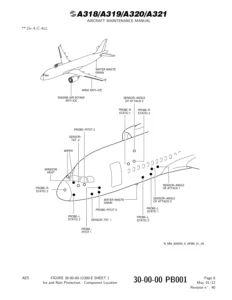
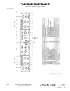
Boeing 737-800 & 737-8 MAX eX1 Center Header Assembly Maintenance Manual Supplement Volume 13 β€” PDF page 1 preview
Boeing 737-800 & 737-8 MAX eX1 Center Header Assembly Maintenance Manual Supplement Volume 13 β€” PDF page 19 preview
Boeing 737-800 & 737-8 MAX eX1 Center Header Assembly Maintenance Manual Supplement Volume 13 β€” PDF page 39 preview

Instant PDF Delivery

This Boeing 737 eX1 Center Header Assembly Maintenance Manual Supplement Volume 13 is delivered as an instant PDF download. No shipping, no waiting. You can view it on any device, print the pages you need for the hangar floor, and keep the complete reference in one file. Whether you are installing a Center Header Assembly for the first time or removing one for a cabin reconfiguration, this volume gives you the complete documentation set.
Reviews

There are no reviews yet.

Be the first to review “Boeing 737-800 & 737-8 MAX eX1 Center Header Assembly Maintenance Manual Supplement Volume 13”

What Our Customers Say

β˜…β˜…β˜…β˜…β˜… Live reviews from customers
Loading customer reviews...
0
    0
    Your Cart
    Your cart is emptyReturn to Shop
    πŸ›’
    Recently Purchased
    πŸ•’ verified order