
BT SPE125 SPE160 SPE125L SPE160L Service Manual PDF Download – 218367-040
Original price was: $54.95.$34.95Current price is: $34.95.
Complete BT service manual for SPE125, SPE160, SPE125L and SPE160L support arm trucks. Covers drive motor, gear, brake, electrical systems, hydraulics, lift chains and control equipment. Valid from serial number 711956-. English, 170 pages, PDF.
Description
BT SPE125, SPE160, SPE125L and SPE160L Service Manual – Order Number 218367-040
This BT SPE125 / SPE160 / SPE125L / SPE160L service manual is the complete workshop reference for BT’s battery-driven support arm trucks. Issued by BT Products AB under order number 218367-040 and dated 2004-04-05, it applies to all four models from serial number 711956- onward. Whether you are maintaining a single truck in a warehouse fleet or running a full service workshop, this PDF gives you the procedures, values, diagrams and troubleshooting guidance needed to keep these machines running correctly.
File Details
- Manual type: Service Manual
- Brand: BT (BT Products AB, Mjölby, Sweden)
- Models covered: SPE125, SPE160, SPE125L, SPE160L
- Valid from serial number: 711956-
- Order number: 218367-040
- Date of issue: 2004-04-05
- Language: English
- Page count: 170
- File format: PDF
Chapters Covered
- Presentation of the truck (M2)
- Technical data (M4)
- Installation and maintenance instructions (P1)
- Maintenance schedule (P2)
- Oil and grease specification (P3)
- Tools (P4)
- Electric drive motor (1760)
- Drive unit/gear (2550)
- Electromagnetic brake (3370)
- Electrical systems (5000)
- Hydraulic system (6000)
- Main lift chain system (7120)
- Control/computer equipment (8700)
Presentation of the Truck (M2)
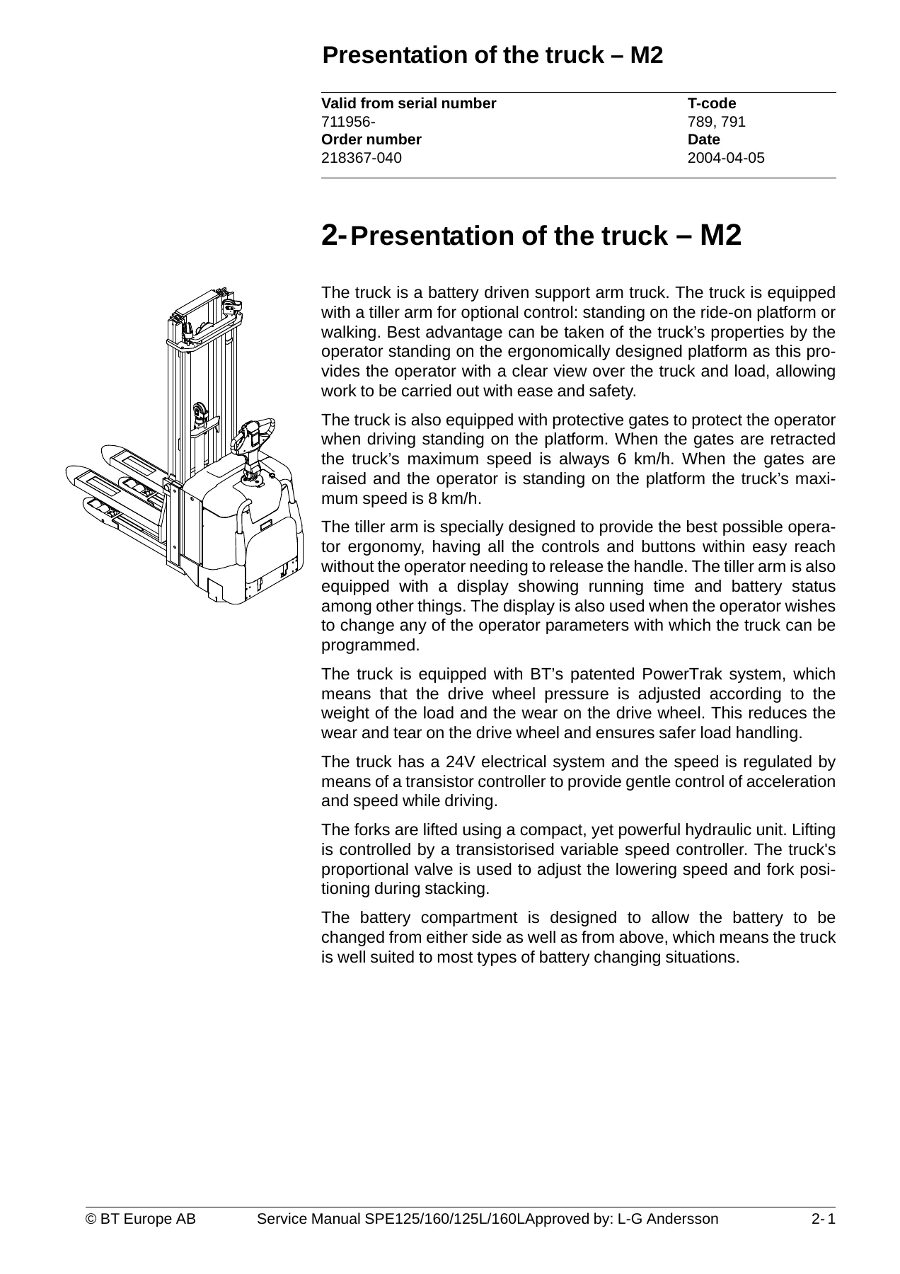
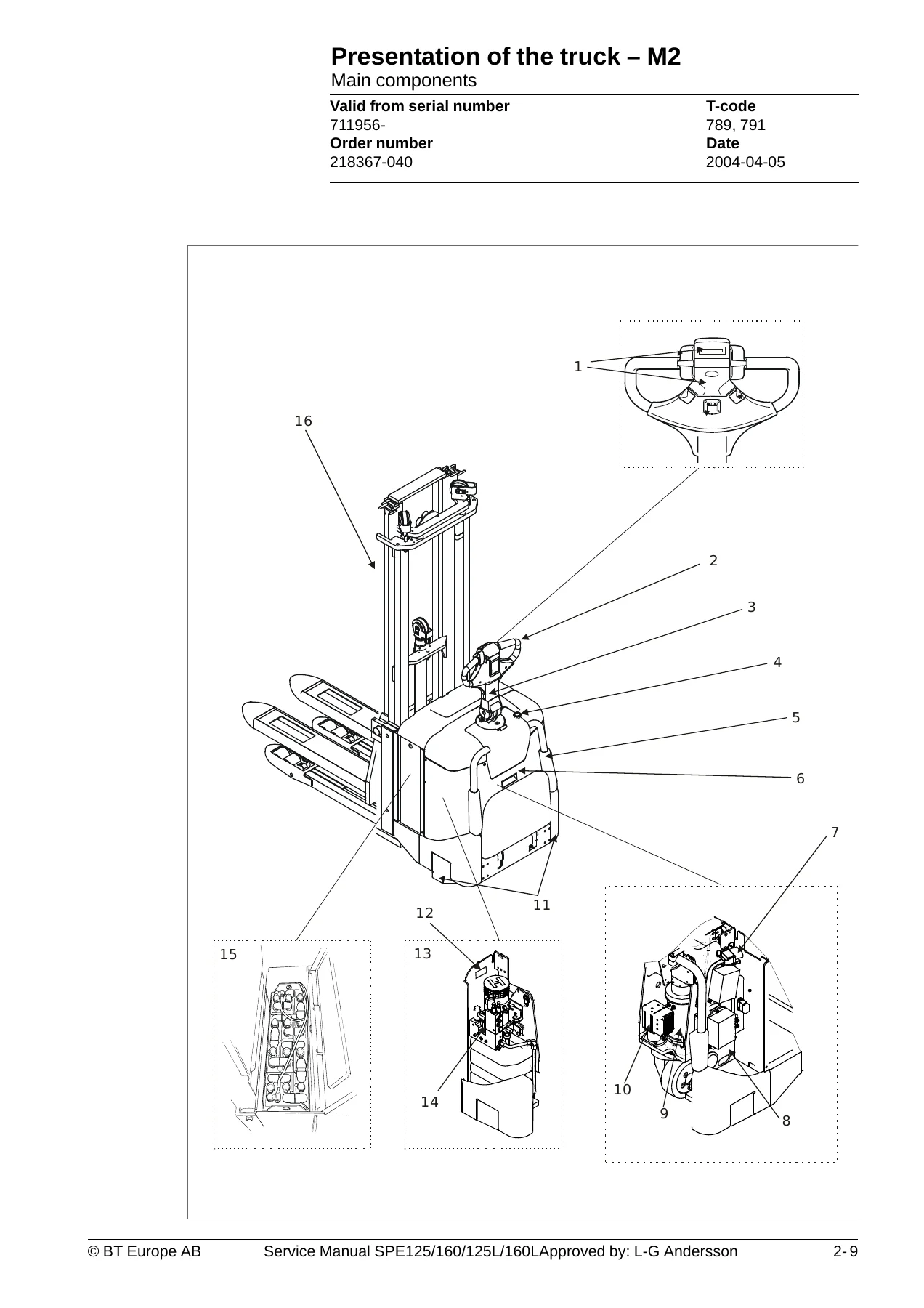
This opening chapter introduces the SPE125 and SPE160 series, explaining intended applications and forbidden uses. It includes the truck data table covering rated capacity (1250 kg for SPE125/125L, 1600 kg for SPE160/160L), lift heights from 2350 to 5400 mm, travel speeds with and without load, gradient capability, truck weights with and without battery, turning radius, noise level and permitted drive wheel materials. Full external dimensions are given in table form for all four variants, along with identification plate, capacity plate and double pallet handling capacity plate details. The main components section describes the hydraulic control, tiller arm, emergency switch off, side guards, cover, battery disconnector, electric panel, drive unit with brake, power steering unit, support castor wheels, hydraulic unit, mast and battery. Warning and information plate positions are also shown.
Technical Data (M4)
The technical data chapter provides the general tightening torque table for millimetre threads M3 to M24, covering both galvanised non-oiled and untreated oiled bolts across strength grades. This is the reference you will return to whenever a fastener torque is not specified in a specific repair procedure.
Installation and Maintenance Instructions (P1)
This section covers lifting the truck at its centre of gravity with the correct fork positions, battery installation with polarity warnings, and a pre-delivery inspection checklist covering hydraulic functions, operating controls, safety reversing switch, horn, steering, brakes, emergency switch off, oil levels, drive unit noise, wheels, chassis, battery cover, fork carriage, lifting device, finger guard, hydraulic cylinders and running time. Safety rules for maintenance work are detailed, including short-circuit and burn injury warnings, hydraulic system depressurisation, hot oil hazards, welding precautions and paint removal requirements. Cleaning and washing instructions cover external cleaning, motor compartment cleaning and electric component care. Safe lifting procedures with jacking and trestle guidance are also included.
Maintenance Schedule (P2)
The maintenance schedule is presented as a comprehensive table with intervals at 5, 20, 80, 500, 1000 and 3000 hours, cross-referenced to days, weeks, months and years. Work items are listed for the chassis, fork carriage, frame-mounted components, drive motors, drive unit, brake, wheels, tiller arm, electrical functions, battery, power system, hydraulic system, lift cylinder and mast. Each item is coded I (inspect/rectify/change), T (tighten), C (clean), L (lubricate) or M (control measurement). Footnotes explain first-time re-tightening at 500 hours, oil change intervals, and the 250-hour schedule for cold stores or severe conditions.
Oil and Grease Specification (P3)
This chapter lists the recommended lubricants, hydraulic oils and transmission oils with their specifications. It includes a temperature-based viscosity table covering ambient ranges from below -40°C to +80°C, with recommended products from Klüber Lubrication, Fuchs DEA and Rexnord. The grease specification table covers wheel bearings, mast beams, lifting chains, hydraulic systems, steering bearings and drive gears.
Tools (P4)
Tooling for Super Seal connectors, AMP connectors (Power Timer, Junior Power Timer, Micro Power Timer and 040 series) and Molex connectors is documented with part numbers and application notes. Other tools include the CAN service instrument, service instrument for programme changes and the driving gear puller.
Electric Drive Motor (1760)
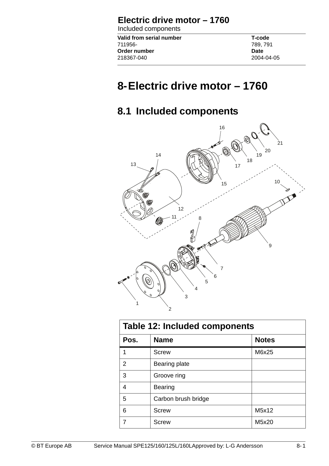
The drive motor chapter covers the TSL140B-DS41 motor with included components, disassembly and assembly of the truck motor, motor service and repairs including rotor removal and gear wheel removal, motor installation, cleaning procedures using vacuum, compressed air and solvents, and technical data covering output, duty cycle, minimum carbon brush length, commutator diameters, winding resistances and insulation resistance.
Drive Unit/Gear (2550)
This chapter documents the 2-stage angle transmission with 14.20:1 or 16.29:1 gear ratio, 1.75 or 1.0 litre oil capacity depending on specification, hypoid oil types for normal and cold temperatures, and procedures for leakage from the top cover and replacing the drive axle jointing ring. Detailed disassembly and assembly instructions include bearing removal, jointing ring replacement, spacing washer checks, axle nut torque of 300 Nm, cover screw torque of 26.6 Nm and drive wheel screw torque of 65 Nm.
Electromagnetic Brake (3370)
The brake chapter covers the BFK458-12 brake with 32 Nm braking force and 40 W output. Main components are identified including magnet coil, pressure plate, pressure spring, friction plate, adjusting locking nut, brake disc, mounting bolts and hub. Maintenance procedures cover basic adjustment of the play to 0.3 mm (maximum 0.8 mm before adjustment), brake disc replacement when thickness reaches 8.8 mm from the new 10.0 mm thickness, and mounting bolt torque of 9.5 Nm.
Electrical Systems (5000)
The electrical systems chapter is the largest section. It begins with an electrical equipment overview and a comprehensive equipment list covering energy and main power isolation, equipment protection, control and signal processing, braking, safety and supervision, traction and traction control, steering, forks lift and support arm lift. Eight full wiring diagrams are included. The functional description uses a numbered event table covering battery connection, switch on with PIN-code entry, tiller arm lowering, traction in both directions, neutral braking, reverse braking, mechanical brake operation, steering, fork lifting, fork lowering, support arm lifting and lowering, and Powertrak operation. The steering system is described in detail with its synchronous DC motor, 4-quadrant regulator, Hall sensors and CAN bus communication. Speed limitation is summarised in a table covering load, fork lift height, driver position and maximum speed. Hour meter and battery condition displays are explained. Diagnostic and troubleshooting includes fault codes C19 through C82 and E90 through E214, with possible causes and solutions. Transistor regulator troubleshooting covers the Curtis 1243 with its error codes, resetting procedures and safety warnings. Built-in test function, display test mode, part numbers and parameters are all documented, including driver parameters (2-7) and service parameters (10-39) with full descriptions. Option parameters 15-19 are covered with configurable option lists and movement selection tables. Curtis 1243 technical specifications complete the chapter.
Hydraulic System (6000)
The hydraulic chapter includes separate diagrams for SPE125L/160L and SPE125/160, main components identification, and a description of the lifting system covering pump motor speed control, non-return valves, routing valve, overflow valve, pressure sensors, proportional valve, lowering valve and PowerTrak system. Working pressure is given as 110 bar for all models, with overflow valve opening at 200 bar. The pressure sensor adjusts travel speed based on load, with 8.0 km/h below 800 kg and 7.0 km/h above 800 kg declining linearly to maximum load.
Main Lift Chain System (7120)
The chain chapter covers general information, chain setting checks, and detailed chain inspection covering noise, surface rust, rusty links, stiff links, bolt rotation, loose bolts, outline wear, stretching, damage, damaged discs, damaged bolts and dirty chains. Cleaning and lubrication procedures are given with recommended products for different temperature ranges. Chain stretching limits are tabulated for 3/4″ and 1″ chains in various configurations, with nominal and maximum permitted chain lengths for 20, 30 and 50 disc sections.
Control/Computer Equipment (8700)
The final chapter is the TruckCom 3.4 user manual for trucks using the PowerDrive platform. It covers connection via CPC-PP CAN interface, the main program screen layout with menu bar, tool buttons, nodes, icons, information window and status bar. Connection and disconnection functions are explained. Downloading program function covers normal downloading for trucks with key and keypad, emergency downloading and downloading in old versions of logic cards. Truck report, parameters function (driver, truck and time tabs), diagnostics function (tiller arm, drive controller and EPS tabs) and other menu functions are all documented. Installation instructions for Windows 95/98, XP/2000 and NT are included, along with CAN communication troubleshooting and uninstall procedures.
Why This BT Service Manual Matters
These BT support arm trucks are robust industrial machines, but they demand correct maintenance and precise repair procedures to stay productive and safe. The SPE125, SPE160, SPE125L and SPE160L service manual gives you the exact torque values, adjustment clearances, fault code diagnostics and hydraulic pressures that generic guides simply do not provide. From the electromagnetic brake play adjustment (0.3 mm) to the drive axle nut torque (300 Nm) and the transistor regulator error codes, every critical specification is documented in a single PDF. The eight wiring diagrams and two hydraulic diagrams alone are invaluable when tracking down electrical or hydraulic faults. The fault code list with possible causes and solutions will save hours of diagnostic guesswork on everything from butterfly sensor warnings to steer servo errors. The maintenance schedule ensures you never miss a service interval, and the lubrication chart keeps every bearing, chain and gear properly protected.
IMAGES PREVIEW
Instant PDF Delivery
This BT SPE125 SPE160 SPE125L SPE160L service manual is delivered as an instant PDF download. No shipping, no waiting for a physical book. Once payment is complete you can download it immediately and open it on any device – laptop, tablet or smartphone. Print the pages you need for the workshop, or keep the entire manual on a tablet for quick reference while working on the truck. The PDF format makes it easy to search for specific fault codes, torque values or procedures, and you can print as many copies as you need for your team.


Reviews
There are no reviews yet.