
Case SV208-SV228 Single Drum Roller Workshop Manual | Cummins Tier 1-3 | 71114345 PDF Download
Original price was: $55.95.$34.95Current price is: $34.95.
Complete Case SV208, SV210, SV211, SV212, SV216, SV223 and SV228 single drum roller workshop manual, publication 71114345. Covers engine removal, drum and vibrator overhaul, articulated joint, clutch, steering cylinders, electrical installation, hydraulic circuits and fault diagnosis for Cummins Tier 1, Tier 2 and Tier 3 machines.
Description
The Case SV208, SV210, SV211, SV212, SV216, SV223 and SV228 single drum roller workshop manual (publication 71114345 SP, dated July 1, 2008) is the full service reference for this family of self-propelled vibratory compaction rollers running Cummins Tier 1, Tier 2 and Tier 3 diesel engines. It treats the machine as what it is: a drum unit and a trailer unit joined by an articulated joint, and it walks a technician through engine removal, drum and vibrator overhaul, hydraulic motor replacement, steering cylinder re-sealing, electrical installation and hydraulic fault diagnosis in the order the work is genuinely carried out in the shop.
Unlike a generic roller book, this Case single drum roller workshop manual is written around the actual SV series hardware — the SV 208 and SV 210 compact rollers, the SV 211, the SV 212 and SV 216 mid-size machines and the heavy SV 223 and SV 228 — and around the Cummins engines that sit in them, so the torque figures, capacities and special tools you reach for are the ones that belong to your machine.
File Details
- Manual type: Workshop / Service Manual
- Brand: Case (CASE Construction Equipment)
- Models covered: SV 208, SV 210, SV 211, SV 212, SV 216, SV 223, SV 228 (single drum rollers, d / Pd / Pdb variants, HD and HT versions)
- Engine coverage: Cummins Tier 1, Tier 2 and Tier 3
- Publication number: 71114345 SP
- Publication date: July 1, 2008
- Language: English, Spanish
- Page count: 340
- File format: PDF
Chapters Covered
- Introduction
- Safety Precautions
- Safety Instructions for Repairs
- Summary of Applications
- Description of the Machine
- Engine Removal
- Drum Removal
- Articulated Joint
- Clutch and Transmission Removal
- Steering Cylinders
- Controls
- Operator’s Position
- Heater Disassembly
- Electrical Installation
- ROPS Structure Removal
- Segment Assembly
- Wheel Removal
- Hydraulic Motor Removal
- Hydraulic Pressure Filter Change
- Hydraulic Oil Supply
- Level Meter Removal
- Float Disassembly
- Electrical Schematic
- Hydraulics
- Hydraulic System Fault Diagnosis
- Problem Solving
- Verification of the Adjustment of Bolted Connections
Introduction, Safety Precautions and Safety Instructions for Repairs
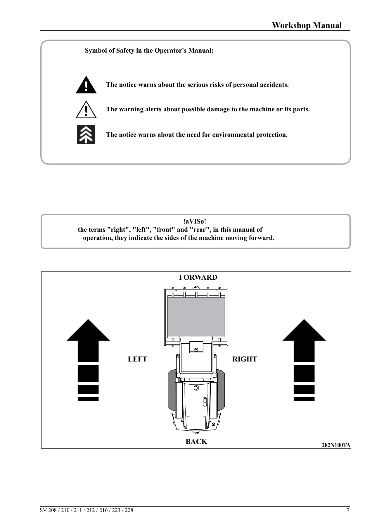
The opening chapters set out how the manual is organised, define the right / left / front / rear convention used throughout the SV series roller, and explain the safety symbol system — the black triangle for personal danger, the open triangle for machine damage and the triple-arrow environmental mark. The safety chapters go far beyond boilerplate: starting and stopping procedure, parking on slopes, working near power lines and buried utilities, towing and transport, tyre and rim handling, battery and electrolyte hazards, high-pressure hydraulic fluid injection injuries, fire prevention, chemical handling and correct waste disposal. The repair-safety chapter adds the workshop-specific rules — securing the drum and frame against rotation, isolating batteries, depressurising hydraulic circuits before breaking a joint, and the hygiene and ecological measures that apply to used oils, coolant, refrigerants and filter elements.
Summary of Applications and Description of the Machine
These two chapters identify the machine and its variants. You get the location and layout of the machine data plate and the Cummins engine serial-number plates, plus the fill-in record table for machine type, serial number, year of build and engine number that a dealer or the manufacturer asks for when parts are ordered. The description chapter then explains the two-part construction of the roller — the drum unit with its gear transmission and vibration transmission, and the trailer unit — and spells out the difference between the smooth drum (d), sheep’s foot drum (Pd) and sheep’s foot plus dozer blade (Pdb) versions, along with the HD and HT build codes for machines with greater traction force and machines designed for permanent operation on gradients above 30 percent. Accessory equipment including goat’s foot segments, the dozer blade and the ROPS structure is described here as well.
Engine Removal
A complete removal and reinstallation procedure for the Cummins engines used across the SV 208 to SV 228 range, with the technical data tables for each engine variant. The chapter lists manufacturer, engine type, number of cylinders, bore, stroke, total displacement, output to ISO 3046/1, rated speed, maximum torque, and fuel consumption in normal operation for the B4.5-C99, the 4BTA 3.9-C116, the QSB5.9-C155, the QSB4.5-C160 and the QSB5.9-C205. The step-by-step sequence covers raising and propping the hood, disconnecting the electrical wiring, releasing the hood lift cylinder pins, removing the hinges, draining the coolant, disconnecting the cooler and steering pump hoses, removing the radiator, air filter and muffler, disconnecting the fuel lines, lifting the cabin, releasing the coupling, taking out the front and rear rubber mount nuts and lifting the engine clear on the crane. Engine oil and coolant specification tables, antifreeze concentration limits, water quality criteria and the engine troubleshooting chart of symptoms, causes and remedies close the chapter.
Drum Removal
One of the longest chapters in the manual. It opens with a warning that drum support in the frame differs between the SV 223 / SV 228 and the SV 208 to SV 216 machines, then gives the drum diameter, drum diameter over the sheep’s feet, drum width, drum thickness, number of feet and foot dimensions for every model. Vibration is generated by two pairs of eccentrics on either side of the drum, driven by a hydraulic motor on the left and with the drum propelled by a hydraulic motor on the right, and the removal sequence reflects that. You get the procedure to raise and support the drum frame, remove the vibration motor cover and hoses, take out the hydraulic motor, remove the cross member, release the rubber supports, withdraw the drum, drain the vibrator oil, dismantle the vibrator plate, pull the tapered bearing inner rings, replace the seals with the specified pre-heat temperatures and refit the assembly with the correct bearing pull-out torque and axial play. Rubber support replacement on both sides of the drum is covered with its own tightening torque table.
Articulated Joint
Describes the joint that connects the drum frame to the rear frame — on the SV 208 to SV 216 a large crossed-roller bearing plus two vertical pins, on the SV 223 / SV 228 the same large crossed-roller bearing with a single vertical pin. Structure oscillation limits in the horizontal plane and maximum steering angles for each machine group are tabulated. The removal sequence covers supporting the frame front and rear, removing the shims, extracting the steering cylinder piston-end pins and rings, taking off the hose clamps, removing the vibration hydraulic motor, suspending the drum and frame, removing the joint screws, splitting the assembly, removing the covers and separator shoes and pulling the bearings.
Clutch and Transmission Removal
Covers taking out the tandem hydraulic generators, the flange and the clutch coupling that sits between the drive engine and the hydraulic transmission. The procedure explains raising the cabin, disconnecting the hoses and electrical wiring from the generators, supporting the units on the crane, releasing the flange screws, sliding out the clutch, stripping the A and B coupling segments, and the reverse sequence for reassembly. Two torque values govern the rebuild — the T1 segment screws and the T2 coupling screws — and the chapter also explains the axial play measurement between the balance wheel face and the elastic clutch element, which must come out at 1 to 3 mm, plus the handling rules for the adhesive-coated countersunk screws.
Steering Cylinders
Removal of the steering cylinder from the machine, disassembly, seal replacement and reassembly. The exploded illustration identifies every component of the cylinder, the kit contents are listed by position number, and the chapter stresses lubricating the sliding faces, checking them for damage, and leaving at least 15 minutes between installing the new seals and completing the assembly. Separate tightening torque tables are given for the piston-rod connection and the cylinder body / cap connection on the three cylinder sizes — the 80/40-400 used on the SV 208 / SV 210, the 90/45-400 on the SV 212 / SV 216 and the 110/55-400 on the SV 223 / SV 228.
Controls and Operator’s Position
The controls chapter covers the travel controller — which doubles as auxiliary and parking brake and carries the vibrator button — and gives the procedure to strip and rebuild the steering column, steering wheel, bearing and retaining rings. Throttle control removal and installation, throttle cable adjustment, the brake adjustment on the control unit and the electrical connections are all shown. The operator’s position chapter deals with the driving station, the cab, the front and rear windscreen wipers, the door locks and the seat, with the torque values for the wiper arm nuts.
Heater Disassembly
Draining the coolant, lifting the cabin, removing the heater cover, disconnecting the air pipes, wiring and water valve, detaching the heater feed and return hoses and taking out the heat exchanger and the heating unit. The air conditioning section explains the refrigeration circuit from the evaporator to the condenser, compressor, dehydrator filter and expansion valve, lists the cooling capacity, working voltage, current draw, air volumes, refrigerant type and refrigerant charge weight and the high and low pressure protection values, and provides a fault chart for a unit that will not cool. Belt adjustment on the compressor is shown with the tension direction marked.
Electrical Installation
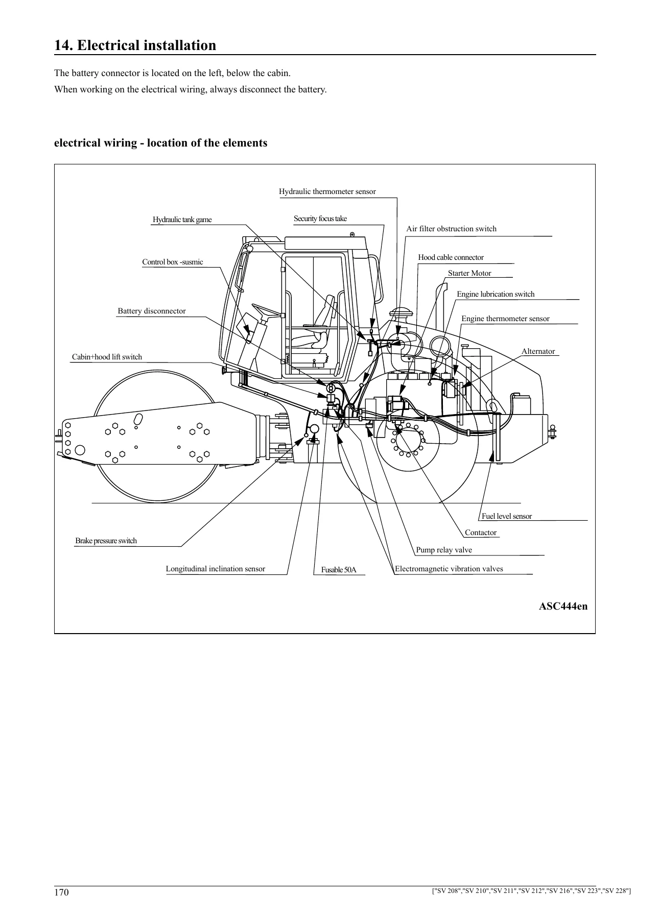
The full electrical chapter for the SV series rollers, organised by engine tier. It describes the fuse box layout and the function of each fuse for the Tier I machines, for the QSB5.9 Tier II machines and for the Tier III machines, including the engine fuses. The battery section covers electrolyte filling, specific gravity targets, charging current, charge level against electrolyte density, maintenance during operation and the slow-discharge charging interval. Alternator construction, the integrated voltage regulator, the regulated voltage range and the inspection and defect-finding procedures for both alternator and regulator are given, followed by starter motor operation, no-load testing, defect diagnosis and the starter motor fault / cause / remedy table. The chapter closes with tachometer replacement and calibration for the Tier 1, Tier 2 and Tier 2 B4.5-C99 engines and the electrical wiring element location diagram.
ROPS Structure Removal and Segment Assembly
The ROPS chapter is short and direct — suspending the structure on the crane and releasing the mounting screws. The segment assembly chapter is more involved and shows how to fit goat’s foot segments to a smooth drum: removing the front and rear scrapers, cleaning the drum surface, suspending and locating the first segment, securing it with clamps, driving slowly forward to position the second and third segments with the correct gap between them, connecting the segments with the specified fasteners, then tightening and re-checking the screws after the machine has been moved so the segments settle on the drum. Scraper clearance to the drum is set here as well.
Wheel Removal and Hydraulic Motor Removal
Wheel removal covers supporting the rear frame, removing the wheel mounting screws and washers, taking off the tyre and disc with the lifting device and refitting the replacement tyre and disc to the specified torque. The hydraulic motor chapter handles the hood lift cylinders, the cabin lift cylinders and the linear hydraulic motors, including seal replacement, the seal kit contents, the 15-minute wait before completing assembly after new seals are fitted, and the torque tables for the 40/22 and 25/18 linear motors.
Hydraulic Filter Change, Oil Supply, Level Meter and Float
The routine service chapters. Hydraulic pressure filter replacement gives the filter body wrench size, the drum-frame serial-number break points from which the layout applies, the procedure to unscrew the cover and drain the oil, the cartridge change and the cover tightening torque. Hydraulic oil supply shows the quick-coupling filler throat and the filling sequence. Level meter removal covers the tank lid, gauge cover, mounting screws and wiring. Float disassembly covers the float cover clamp, wiring disconnection and the connection screws.
Electrical Schematic
The wiring diagrams for the SV series. Separate schematics are provided for the Tier I machines with the two-valve and four-valve ATC and inter-axle differential lock, for the SV 208 / SV 210 with the B4.5-C99 Tier II engine, for the SV 212 / SV 228 with the Tier II engine, and for the Tier III machines. Component reference lists sit alongside each diagram, covering switches, sensors, relays, fuses, motors, solenoid valves, connectors and the electronic control units, along with the notes on which semiconductor components must be disconnected before any welding is carried out on the machine.
Hydraulics
The hydraulic circuit schematics for the three machine groups — SV 208 / SV 210, SV 212 / SV 216 and SV 223 / SV 228 — each drawn in several states so you can follow the oil path with the valves in different working positions: normal work, differential lock engaged and differential lock disengaged. Every diagram is keyed to a numbered legend naming the gear pump, vibration pump, drum transmission hydraulic motor, vibration motor, wheel hydraulic motors, steering pump, steering unit, steering cylinders, divider block, pressure switch, suction strainer, filter block, cooler, thermoregulator, quick couplings, temperature sensor and the lift cylinders. Model-specific notes identify which pump and motor combination belongs to the SV 212 and which to the SV 216.
Diagnosis of Defects in the Hydraulic System
A dedicated diagnostic chapter listing the recommended tools for servicing the Sauer 90R pumps and motors, the test point values for each machine group, and the adjustment procedures for the charge pressure relief valve, the high-pressure relief valve inside the multifunctional valve and the shut-off valves. Vibration frequency adjustment is covered in detail for all models, with the high and low amplitude frequency values in Hz and vibrations per minute, the position of the adjustment screws on the vibration pump, and the warning that every frequency adjustment is made with the engine stopped. Engine maximum speed and idle speed adjustment for the Tier 1 and Tier 2 engines is included, together with the emergency release procedure for the wheel and transmission hydraulic brakes when a machine has to be towed.
Problem Solving and Torque Verification
The problem solving chapter is a symptom-driven index of the faults an SV roller owner or technician actually meets — oil leaking under the vibration cover, vibration that will not engage, the machine shutting down spontaneously, the engine dying, only one travel range available, brakes that stay on, brakes that are always off, low tractive effort, the ATC not working, steering that does not respond, steering that works one way only, hydraulic oil leaking from the tank, foaming oil and overheating oil. The final chapter is the torque verification chapter: the general torque table for dry 8.8 and 10.9 grade fasteners from M6 up to M30, the torque table for O-ring sealed hose fittings and the torque table for plug and neck connections with flat joints, so that every threaded joint in the machine can be tightened to the correct figure.
Models, Engines and Variants in This Manual
This Case single drum roller service manual covers seven models across three Cummins engine tiers. The SV 208 and SV 210 use the Cummins B4.5-C99 Tier II engine at 74 kW (99 HP) and 2200 RPM. The SV 211 runs the Cummins 4BTA 3.9-C116 Tier I engine at 86 kW (116 HP) and 2500 RPM. The SV 212 and SV 216 are covered with both the Cummins QSB5.9-C155 Tier II engine at 116 kW (155 HP) and the Cummins QSB4.5-C160 Tier III engine at 119 kW (160 HP). The SV 223 and SV 228 use the Cummins QSB5.9-C205 Tier II engine at 153 kW (205 HP) and 2500 RPM. Each model is documented in the d (smooth drum), Pd (sheep’s foot drum) and Pdb (sheep’s foot drum with dozer blade) variants where those exist, and the additional HD and HT build designations are described so that weight, traction and gradient limits are read against the correct machine. Operating weights, drum dimensions, travel speeds, turning radii, tyre sizes and inflation pressures for every model are tabulated in the machine description chapter.
Who This Case Roller Workshop Manual Is For
Independent heavy equipment mechanics servicing Case single drum rollers in a workshop or on site. Fleet maintenance departments keeping SV series compactors in service. Owner-operators who want to carry out their own servicing, seal replacement and fault finding rather than sending every job out. Dealership technicians who need the factory removal, assembly and adjustment sequence in front of them. Technical colleges and training workshops working on vibratory compaction equipment. Anyone rebuilding a drum, a vibrator, a steering cylinder or a hydraulic drive on an SV 208 through SV 228 machine and needing the real torque values, the real seal installation temperatures and the real test point pressures rather than a guess.
Why the Correct Procedure Matters on a Vibratory Roller
A single drum roller is a compaction machine, and compaction is delivered by a vibrating drum carrying a tuned eccentric mass. Get the bearing pre-load, the axial play or the rubber support torque wrong and the drum does not simply run rough — it destroys the vibrator bearings, cracks the drum shell and takes the frame with it. The hydraulic side is no more forgiving: this manual sets out the exact test points, the pressure values for the travel, vibration and steering circuits, the charge pressure and the multifunctional valve adjustment, so a pump or motor fault is identified by measurement rather than by parts swapping. On the electrical side, the roller carries an electronic control unit for the ATC, speed sensors, solenoid valves and a J1939 network on the later machines, and the manual warns plainly that welding must not be carried out without isolating those components. Working from this Case SV208-SV228 workshop manual means the jobs are done once, to the figures the machine was built to.
IMAGES PREVIEW
Instant PDF Delivery
This is a digital workshop manual, not a printed book. The moment your payment is confirmed the PDF is available to download — there is no shipping, no waiting and no customs. The file opens on a laptop, desktop, tablet or smartphone, and because it is a PDF you can print the pages you need for the workshop bench, keep the rest clean on screen, and search the text for a model number, a torque figure or a fault symptom when you are standing next to the machine. Print the whole manual and put it in a binder, or print the single chapter you are working from and throw it away when the job is done. Either way, the complete 340-page Case SV208-SV228 single drum roller workshop manual, publication 71114345 SP, is in your hands in minutes.
Reviews
There are no reviews yet.